There are multiple kinds of Peripheral Interface Controller (PIC) but here we will learn about one small size and low-cost PIC microcontroller. PIC12C508 is a small-sized with a high-performance 8-bit microcontroller. It is based on a CMOS technology that comes up with an 8-bit full static ROM, EPROM, and EEPROM. PIC12C508 has 8 digital pins and internal 4MHz Oscillator which can be controlled by programming. It is designed in a variety of different packages and multiple features. PIC12C508 microcontroller is designed with special features, which gives the reduction in power and cost, it also comes in the OTP package which is suitable for any large volume.
Recommended Components
The following parts are used in this article, along with a generic electronics kit that is handy for building and testing the circuit.
| Component | How it’s used | Buy on Amazon |
|---|---|---|
| PIC12C508 microcontroller | The PIC12C508 8-bit PIC microcontroller this article covers. | Check Price |
| Electronic component assortment kit (1390 pcs) | A handy assortment of resistors, capacitors, LEDs, diodes and transistors for building circuits. | Check Price |
| Digital multimeter (AstroAI) | Measures voltage, current, resistance and checks continuity while you build and debug. | Check Price |
| Breadboard | Solderless base for prototyping the circuit. | Check Price |
| Jumper Wires | Make the connections on the breadboard. | Check Price |
As an Amazon Associate we earn from qualifying purchases. Prices and availability are accurate as of the date/time indicated and are subject to change.
PIC12C508 Pinout diagram
This is a pin configuration of PIC12C508 microcontroller and step by step explanation of each pin is given in this section.
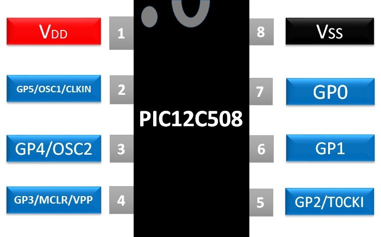
PIC12C508 consist of 8 pins, in which 2 of them are power pin and the remaining pins are a digital pin, those pins are designed to use for multiple purposes. Even some pins can be used for multiple purposes, which we are going to discuss:
POWER PINS
In PIC12C508 pin 1 & 8 will be used for power input. Pin 1 will for power input and Pin 8 will be used for common ground.OSCILLATOR PINS
Every PIC requires a clock pulse to perform a function according to that interval and two pins must be connected to the oscillator to give the controller a clock pulse. There is an internal oscillator attached within the PIC but to use a different oscillator use the following pins.- GP5/OSC1/CLKIN – Pin 2
- GP4/OSC2 – Pin 3
DIGITAL OUTPUTS Pins
In this version of PIC, almost every pin can be used as an output pin. To used them as output only internal programming will be required. The voltage on these pins will not exceed more than the voltage of VDD, and both TTL and ST devices can be controlled directly. To control the high load external peripheral high load will be required. In PIC12C508 the Digital output pins are:- GP0 – Pin 7
- GP1 – Pin 6
- GP2 – Pin 5
- GP4 – Pin 3
- GP5 – Pin 2
DIGITAL INPUTS PINS
The input pin in the PIC can be used for multiple purposes. All input pins can be used for a weak pullup. The input pins will be only able to operate with ST input logic otherwise it could fluctuate between on and off due to improper input logic. The following pins can be used for input pins in PIC12C508:
- GP0 – Pin 7
- GP1 – Pin 6
- GP2 – Pin 5
- GP3 – Pin 4
- GP4 – Pin 3
- GP5 – Pin 2
- GP6 – Pin 1
WAKE UP PINS
PIC12C508 can go automatically to sleep mode, by this functionality the PIC can save power without affecting the performance. To wake up the PIC from sleep some input pins can be used by giving the input but microcontroller should be programmed first to use those pins. PIC12C508 contains three input pins that can be used for wakeup.
- GP0 – Pin 7
- GP1 – Pin 6
- GP3 – Pin 4
T0CKI Timer PIN
Time0 of PIC12C508 will increment in its value at each rising or falling edge from T0CKI pin. Due to the small number of pins in PIC12C508, the IC has only one T0CKI. T0CKI pin will be operated with ST logic input only.- T0CKI – Pin 5
RESET PIN
Every controller comes up with a reset pin to reset its state digitally by using an external button or any signal. The LOW state input signal will be able to reset the controller. The power on the reset pin should not be exceeded from VDD.- MCLR’ – Pin 4
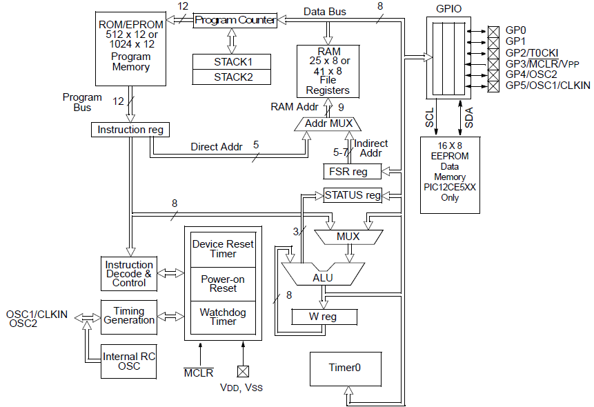
PIC12C508 Block Diagram
PIC12C508 Features
- It has 8-bit timer/counter which also has an 8-bit programmable Prescaler.
- PIC has programmable code protection.
- The EEPROM has 1,000,000 data erase cycles and data has 40years of retention.
- The PIC comes with Power-on Reset and Device on Reset Timer.
- It has a Watchdog Timer with an internal RC oscillator circuit which is reliable in case of hardware or software fault in the embedded system.
- PIC12C508 has the ability to go to sleep mode for power saving and to wake it up from sleep digital signals can be used.
- Weak Pull will be used on the I/O pins in PIC.
SPECIFICATION
- It is a low power consumption controller that can operate at 2mA and 5V.
- PIC comes with an internal Oscillator with 4MHz.
- The Standby current of the controller is 1uA
- Operating temperature range depends on each purpose:
- At Commercial level: 0 to 80 degree
- At Industrial level: -40 to 85 degree
- Extended: -40 to 125 degrees.
PROGRAM MEMORY AND STACK
The flow of the program and stack can be measured by a diagram: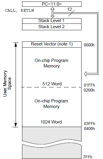
PIC12C508 Applications
- Due to its small size and high performance, it is used in compact devices as a control unit.
- In small security systems like cameras, sensors and locks PIC12C508 are widely used.
- It is used to design low power data transmitters and receivers.
PIC12C508 Instruction Set Architecture
Any of the given lists of the compilers can be used to write the program of the microcontroller. All of the compilers will write the program in assembly language. To write the code some instructions should be kept in mind. In PIC12C508 each instruction given to the controller should be in 12bits. The 12-bit gives the 4 types of instruction which are:
- Byte-Oriented for File Register Operation
- Bit Oriented for File Register Operation
- Literal and Control operations
- 8 – bit
- 9 – bit
Byte-Oriented for File Register Operation
In Byte-Oriented file register, the least five bits will the file register address, the next one bit will represent the destination and the first 6-bits will be the OPCODE which is used by the machine learning instructions.| OPCODE (6-bit) | DESIGNATION (1-bit) | FILE ADDRESS (5-bit) |
|---|
Bit Oriented for File Register Operation
In the Bit-Oriented file register, the last 5 bits will be for file register address, the next 3 will be for bit address and the rest of the 4-bit code will be for OPCODE.
| OPCODE (4-bit) | BIT ADDRESS (3-bit) | FILE ADDRESS (5-bit) |
|---|
Literal and Control operations
In literal and Control operations there will be only two parts part will be for OPCODE and rest of them will be for the literal value of control operation. In Literal and Control Operations, for GOTO instruction OPCODE will be of 3 bit and literal will be of 9 bits but in other cases expect GOTO operation the literal will be of 8 bits and OPCODE will be of 4 bits.
| OPCODE (4-bit) | FILE ADDRESS (8-bit) (except GOTO instruction) |
|---|
| OPCODE (3-bit) | FILE ADDRESS (9-bit) (GOTO instruction) |
|---|
PIC12C508 Assembly Language Instructions Set
Every single operation in the PIC12C508 will be handle by mostly Assembly language and by using assembly language data will be processed from register to register to perform each and every operation. Some main registers which will be mostly used are file address register and working register. These two registers will be represented by f and W. These two registers locations will be defined by Destination select bit in each instruction format. These two registers will be used for most every operation but the rest of the registers have also some uses. You can check tutorials for a complete guide of PIC microcontroller assembly language programming:
To specify the remain registers and operation we will need to use the specific symbol/values. Here’s the list of all the remaining operations and registers:
 These all are the register and operations which will be used for multiple purposes. Some of them are literal, designation and rest of them are register address or data. The OPCODE will be used with them to perform the specific operation and for each and every operation OPCODE will be different. The list of the OPCODE is given below:
The OPCODES are in assembly language and they could be used by any given development tool, but maybe you find it difficult to understand and could find some better tools in high-level language on the internet.