PIC12F508 is an 8-bit middle range microcontroller from Microchip. Here, PIC stands for Peripheral Interface Microcontroller. PIC12F508 is a cost-effective, high-performance flash microcontroller that permits us to add intelligence to our projects. It comes with a high-performance RISC CPU with only 33 single-word instructions. All instructions take one cycle to execute except for the branch instructions which takes 2 CPU cycles.
PIC microcontrollers are designed to be controlled through software to perform various tasks. It comes with Flash memory technology which enables us to reprogram the controller over and over again.
This tutorial is an introduction to the PIC12F508 microcontroller. All the features, specifications, pin configuration, operation of GPIO pins, and applications will be discussed here.
Recommended Components
The following parts are used in this article, along with a generic electronics kit that is handy for building and testing the circuit.
| Component | How it’s used | Buy on Amazon |
|---|---|---|
| PIC12F508 microcontroller | The PIC12F508 8-bit PIC microcontroller (DIP-8) this article covers. | Check Price |
| Electronic component assortment kit (1390 pcs) | A handy assortment of resistors, capacitors, LEDs, diodes and transistors for building circuits. | Check Price |
| Digital multimeter (AstroAI) | Measures voltage, current, resistance and checks continuity while you build and debug. | Check Price |
| Breadboard | Solderless base for prototyping the circuit. | Check Price |
| Jumper Wires | Make the connections on the breadboard. | Check Price |
As an Amazon Associate we earn from qualifying purchases. Prices and availability are accurate as of the date/time indicated and are subject to change.
PIC12F508 Introduction
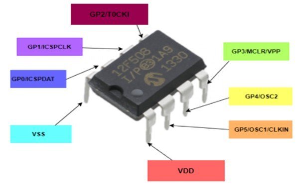
PIC12F508 is used in numerous electronic microcontroller projects. It has 8 pins in total, out of which 6 are GPIO pins. Only one pin can be used as a digital input pin. But you want to use PIC12F508 in your project and you are fall short of GPIO pins, you can use a GPIO expander IC such as 74HC595 and MAX7219.
It comes with a 4MHz of inbuilt oscillator, which can be customized in energy-saving mode. We can also use an external oscillator with pin 2(OSC1) and pin 3(OSC2) but at the cost of GPIO pins. GPIO pins are already limited in PIC12F508. Therefore, it is recommended not to use an external oscillator and for various low-end applications internal 4MHz crystal is more than enough.
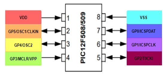
PIC12F508 Pinout
First let’s discuss the pinout digram of PIC12F508 microcontroller. The following diagram shows the pinout of the PIC12F508 Microcontroller:
Pin Configuration
The pin configuration detail in tabular is mentioned below:
| Number | Pin Name | Function |
|---|---|---|
| 1 | VDD | Supply pin for GPIO pins (+5V) |
| 2 | GP5/OSC1/CLKIN | Dual-directional pin GPIO pin / External clock pin/ Oscillator input pin |
| 3 | GP4/OSC2 | Dual-directional pin GPIO pin / Oscillator output pin |
| 4 | GP3/MCLR/VPP | Input pin / active-low Master Reset pin / programming input Voltage pin |
| 5 | GP2/T0CKI | Dual-directional GPIO pin / Clock input to TMR0 pin |
| 6 | GP1/ICSPCLK | Dual-directional pin GPIO pin / In-circuit Serial programmer clock pin |
| 7 | GP0/ICSPDAT | Dual-directional pin GPIO pin / In-circuit Serial programmer clock pin |
| 8 | VSS | Ground pin |
- GPIO pins: It has a total of 8 GPIO pins, out of which 5 are bi-directional input-output pins and 1 input pin.
- In-Circuit Serial Programming (ICSP): PIC12F508 supports circuit programming. It can program the microcontroller in-circuit through serial communication.
- MCLR: It is an active-low master reset of the microcontroller. As it is active-low so consistent supply should be provided to this pin; otherwise, the controller resets itself.
- T0CKI: This pin acts as a clock to the Real-Time TMR0.
- OSC1/CLKIN: It represents oscillator input or external clock input. The respective can be used for either purpose.
- OSC2: It is the oscillator output pin.
- VDD: A power supply of 5 Volts is provided to operate the microcontroller.
- VSS: It provides a ground or zero reference level to the input pins.
PIC12F508 Features and Specifications
| Feature and Peripheral PIC12F508 | Availability |
|---|---|
| Bus Width | 8-bit |
| Architecture | RISC |
| Flash Program Memory (words) | 512 Bytes |
| Data Memory (bytes) | 25 bytes |
| GPIO Pins | 6 GPIO and 1 only input |
| General-Purpose Timers | 1 |
| Internal Pull-ups | Yes |
| In-Circuit Serial Programming | Yes |
| Number of Instructions | 33 |
| ADC | 0 |
| DAC | 0 |
| PWM | 0 |
| UART | 0 |
| I2C | 0 |
| SPI | 0 |
| CAN | 0 |
| Maximum Operating voltage (V) | 5.5 |
| Watchdog Timer (WDT) | Yes |
- DataBus Width : 8bits
- ProgramBus Width : 12 bits
- Pin Count : 8 (PDIP/SOIC/MSOP/DFN)
- Processor Speed: 1 Million Instructions per Second
- Program Memory: 512 words
- StaticRAM: 25 bytes
- Data EEPROM: 25 Bytes
- Operational Temperature : -400C – 1250C
Some of the detailed features listed as follows:
- High-performance CMOS microcontrollers with Flash Technology
- operates at a low power of 2.2 – 5.5 volts, so it is power-efficient
- Each I/O pin can sink/source current of 25mA
- operational frequency is up to 4MHz but can be altered for saving energy
- does need an external circuit to reset it due to a device reset timer and power-on reset
- Programmable code protection for durability
- Watchdog timer to work and wake the device up from sleep mode and can be activated or deactivated through programming
- Electrically Erasable Memory programmable Read-Only Memory of 25×8 bytes to store some of the data permanently
- Program memory of 0.75 KB
- 8-bit RISC architecture based CPU
- 12-bit wide instruction set with 33 single-word instructions
- Completes instructions in one cycle except for program branches, which requires two cycles
How to Program PIC12F508 Microcontroller
PIC microcontrollers can be programmed with different software and compilers.
Supported Compilers
The function of an IDE(Integrated Development Environment) is to provide the environment for programming. The compiler converts the program into readable HEX files. The IPE(Integrated Programming Environment) serves the purpose of burning HEX files in PIC MCUs.
Programming for PIC microcontrollers through assembly language is still functional. Some of the compilers like MPLAB XC8 developed by Microchip manufacturers, MikroC for PIC, and Hi-Tech Compiler are commonly used. You are see these getting started guide:
- MPLAB XC8 Compiler – Write your First Program
- Pic microcontroller programming in c using Mikroc Pro for PIC
- How to Use “MikroC PRO for PIC” to Program PIC Microcontrollers
Programmer to Flash Code
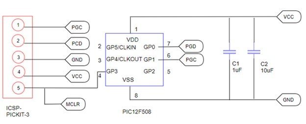
To program PIC12f508, we require an IDE, an IPE, a Compiler, and a programmer/debugger, all provided by MPLAB.
PICKit3 is an In-circuit programmer/debugger which plays an integral role in programming PIC. It supports In-Circuit-Serial-Programming, operated by a computer, to burn the code into PIC using MPLAB. PIC is programmed by using only two pins(PGC and PGD) using PICKit3. No power pins are required. Furthermore, hardware like Perfboard, soldering station, Crystal Oscillator, capacitors, PIC IC is required.
You can see this tutorial on PicKit3:
Alternate Options
- PIC12F629
- PIC12F683
- PIC16F505
- PIC12C508
- PIC16F676
- PIC16F72
- PIC16F873A
- PIC16F876A
- PIC16F886
- PIC16F252
Applications
- Sensor Systems
- Safety devices
- Automation systems
- Cost-effective embedded systems
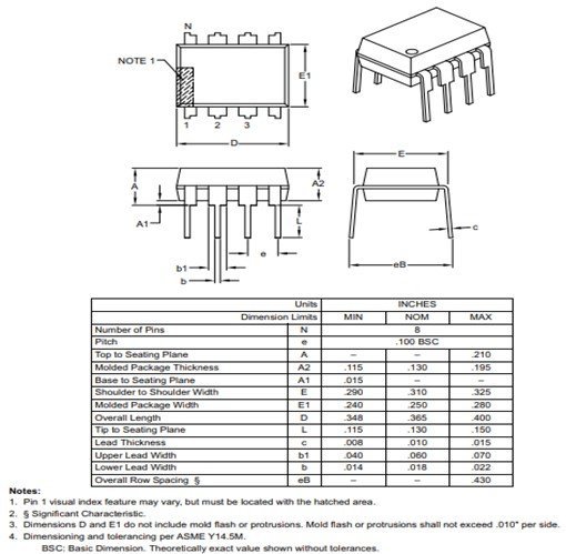
PIC12F508 2D Diagram
PIC12F508 8-bit PIC Microcontroller comes in four packages, i.e., PDIP, SOIC, MSOP, and DFN. The following figure shows the 2d model of PIC12F508 8-bit PIC Microcontroller(PDIP). It shows us the physical dimensions of the components required when a PCB card is designed.
Datasheet
To see further details and specifications of PIC12F508, the link to the datasheet is given below.
Other Pic Microcontrollers:
“GPIO pins: It has a total of 8 GPIO pins”
Should read
“GPIO pins: It has a total of 6 GPIO pins”
No?