PIC16F886 is one of the 8-bit microcontroller made by nano-watt technology. It is preferred by most of the developers for experimenting due to its multiple functionalities at a cheap rate. It comes in 28 pins an internal oscillator that can be variate at a specific range through programming. The 16-byte flash memory of this controller is good enough for most of the applications. PIC16F886 comes with auto Power saving modes and watchdog timer which makes the controller more reliable. It also comes in multiple packages that solve multiple circuitry requirements. It also comes with two programming pins on the microcontroller which makes it easy to program.
PIC16F866 Features
These features are listed according to the datasheet.
| Name | Features |
|---|---|
| CPU Architecture | 8-bit RISC Pipelined |
| CPU Frequency | 20MHz |
| Operating Voltage Range | (2.0V-5.5V) |
| GPIO PORTS | 26 I/O Pins |
| Interrupts | One external interrupt RB0 |
| Timers | 2 8-bit and one 16-bit timer |
| PWM | 1 CCP and 1 ECCP Module |
| UART | One UART channel |
| I2C | One I2C channel |
| SPI | One SPI channel |
| LAN | No Available |
| CAN | No Available |
| ADC | 11 Channel |
| DAC | No Available |
| Enhanced USART Module | 1 Channel |
| SRAM | 368 bytes |
| FLASH ( Program Memory) | 8192 bytes |
| EEPROM | 256 bytes |
| Comparator | 2 |
PIC16F886 Pic Microcontroller pin diagram
The pin configuration diagram and features of this 8-bit pic microcontrollers are shown here as per datasheet:
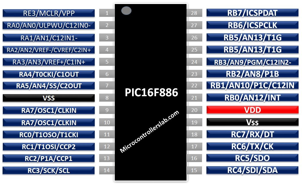
POWER SUPPLY PINS
The PIC16F886 multiple ground pins but it have only one power pin. The PIC can be powered up from a power pin but due to two ground pins, any single ground pin can be used because both of them are connected internally. One ground can be used to make the common ground with the power supply and the second one can be used to make it common with the other operating device with the controller. Power and ground pin in the microcontroller are:
- VSS / Ground – Pin 8
- VSS / Ground – Pin 19
- VDD / Ground – Pin 20
CLOCK/OSCILLATOR PINS
PIC16F886 comes with an internal clock but sometimes its external devices required different oscillator/clock due to their designed requirement. To solve their problem external clock/oscillator pins will be used on the controller. The oscillator pins are two in number one is used for input and second is used for output:
- OSC1/CLKIN – Pin 9
- OSC2/CLKOUT – Pin 10
DIGITAL OUTPUT PINS
Like other microcontroller PIC16F886 also have digital output pins. Total pins of PIC16F886 are 28 in which 24 pins are digital output pins. These pins give the output in only logical states. In PIC16F886 there are 4 ports, three of them are used for General Purpose Input-Output. Two of them (A & B) give the output in TTL form and third port (C) gives the output in Schematic Trigger (ST) form. The maximum output on these pins won’t be more than the power supply of microcontrollers. The output on these pins will be 0 until it is changed through programming. Digital output pins of PIC16F886 are:
- RA0 – GPIO2
- RA1 – GPIO3
- RA2 – GPIO4
- RA3 – GPIO5
- RA4 – GPIO6
- RA5 – GPIO7
- RA6 – GPIO10
- RA7 – GPIO9
- RB0 – GPIO21
- RB1 – GPIO22
- RB2 – GPIO23
- RB3 – GPIO24
- RB4 – GPIO25
- RB5 – GPIO26
- RB6 – GPIO27
- RB7 – GPIO28
- RC0 – GPIO11
- RC1 – GPIO12
- RC2 – GPIO13
- RC3 – GPIO14
- RC4 – GPIO15
- RC5 – GPIO16
- RC6 – GPIO17
- RC7 – GPIO18
DIGITAL INPUT PINS
In PIC16F886 except for power pins all pins can be used as an input pin. All 4 ports can be controlled by programming as an input. The input on Port A, C, E will need TTL based input to operate but Port B will only operate with ST based input. List of all 25 input pins of PIC16F886 are given below:
- RA0 – GPIO2
- RA1 – GPIO3
- RA2 – GPIO4
- RA3 – GPIO5
- RA4 – GPIO6
- RA5 – GPIO7
- RA6 – GPIO10
- RA7 – GPIO9
- RB0 – GPIO21
- RB1 – GPIO22
- RB2 – GPIO23
- RB3 – GPIO24
- RB4 – GPIO25
- RB5 – GPIO26
- RB6 – GPIO27
- RB7 – GPIO28
- RC0 – GPIO11
- RC1 – GPIO12
- RC2 – GPIO13
- RC3 – GPIO14
- RC4 – GPIO15
- RC5 – GPIO16
- RC6 – GPIO17
- RC7 – GPIO18
- RE3 – GPIO1
PWM PINS
PWN pins are known as a pulse with modulation pins. They are used to control the voltage input of the DC devices. These pins come limited in number due to the multiple registers involved in the microcontroller to generate the PWM. In PIC16F886, there are 4 PWM pins which are given below:
- P1A – GPIO13
- P1B – GPIO23
- P1C – GPIO22
- P1D – GPIO25
ASYNCHRONOUS SERIAL Communication PINS
PIC16F886 also have an Asynchronous serial communication port which can be used to receive and send data from any other serial communication device. Asynchronous communication helps the microcontroller to communicate with multiple sensors and modules and make it more reliable for smart tasks. The serial communication needs two data transfer pin one for sending and one for receiving. Both these pins are listed below.
- TX – GPIO17
- RX – GPIO18
SYNCHRONOUS SERIAL COMMUNICATION
Beside Asynchronous there are Synchronous serial communications are also available in the microcontroller, which comes with three pins. One used for clock input, second used for data transfer and third use for power. These pins are mostly used to programmed the microcontroller.
- ICPCLK – GPIO27
- ICPDAT – GPIO28
- VPP – Pin1
- PGM – GPIO14
PGM is used to enable the programming in synchronous serial at low voltage.
SPI Communication PIC16F886
It is the third type of serial communication. It is also like a synchronous serial communication method used to send and receive data and clock from different communication lines. It has four communication lines, two of them are used to send and receive data, third is used to send clock pulse but the fourth communication line known as slave select is used to select the peripheral. In the case of multiple peripheral microcontrollers act as a master and slave select pin will increase in number and will be used to select between multiple devices. In PIC16F886 MSSP pins are:
- SCK (CLOCK PIN) – GPIO14
- SDO (SPI DATA OUTPUT) – GPIO16
- SDI (SPI DATA INPUT) – GPIO15
- SS’ (SLAVE SELECT) – GPIO7
I2C Communication PINS
This protocol almost follows a bit both SPI and Asynchronous serial communication. It is used in the case of multiple peripheral devices. It comes with two communication lines; one is used for clock signal which generates the start condition of a single peripheral and then that specific device starts to send the data through the data line. The pins for I2C communication are:
- SCL – GPIO14
- SDA – GPIO15
TIMERS PIC16F886 Microcontroller
PIC16F886 comes with three timers, two of them are 8-bit (Timer0, Timer2) and the third one (Timer1) is a 16-bit timer. Timer1 also has a control pin know as timer gate, used to control the timer from an external pin and Timer2 is controlled from internally. The timer pins of the controller are:
- T0CKI – GPIO
- T1CKI – GPIO
- T1G’ (Timer1 gate) – GPIO
Time1 also has the ability to count the clock cycle by using a separate oscillator. To use the separate oscillator an external pin will be used:
- T1OSO – GPIO11
- T1OSI – GPIO12
COMPARATOR PINS
In PIC16F886 there are 2 analog comparators, which also have voltage references. These comparators are used to compare the analog inputs and their inputs can be compared according to the power supply power and according to a given voltage reference. The input in the comparator is compared by a non-inverting analog signal. The comparator pins and their reference pins on PIC16F886 are listed below:
- C1IN (+) – GPIO5
- C12IN0(-) – GPIO2
- C12IN1(-) – GPIO3
- C12IN2(-) – GPIO24
- C12IN3(-) – GPIO22
- C1OUT – GPIO6
- C2IN (+) – GPIO4
- C2OUT – GPIO7
- VREF – /CVREF – GPIO4
- VREF (+) - GPIO5
PIC16F886 ANALOG TO DIGITAL CHANNELS
PIC16F886 also comes with an analog to digital converter. It has a 14 analog input that can convert the 14 analog input data signals to a 10-bit digital signal. It also has the ability to convert the input data to digital according to the given voltage reference. The voltage of input analog data and reference voltage should not be exceeded more than the power input range of the microcontroller. The analog pins on PIC16F886 are given below:
- AN0 – GPIO2
- AN1 – GPIO3
- VREF (-)/AN2 – GPIO4
- VREF (+)/AN3 – GPIO5
- AN4 – GPIO6
- AN5 – GPIO7
- AN6 – GPIO9
- AN7 – GPIO10
- AN8 – GPIO23
- AN9 – GPIO24
- AN10 – GPIO22
- AN11 – GPIO25
- AN12 – GPIO21
- AN13 – GPIO26
ENHANCED CAPTURE/COMPARE/PWM Module
PIC16F886 comes with a module that allows the user to control the event according to time. Capture mode allows an event for the peripheral duration of time. Compare mode allows an external event when a specific amount of time has been passed by the controller and PWM is just used to generate the simple PWM signal with respect to time of different frequencies. All these three functionalities come in a single pin and PIC16F886 has two pins of that kind.
- CCP1 – GPIO13
- CCP2 – GPIO12
WAKEUP
In PIC16F886 all input pins can be programmed but those pins require TTL and ST logic to wakeup the microcontroller. When the external pin has low voltage or a chance that voltages can be lower down then a special pin is designed in PIC16F886 to wake up the controller.
- ULPWU – GPIO2
RESET PIN
PIC16F886 can be reset internally but it also has an external pin that can be used by any other device or button to reset the microcontroller in case of requirement.
- MCLR’ – GPIO1
Alternative Options
Other 8-bit pic microcontrollers are: PIC18F452, PIC18F4550, PIC16F46K22, PIC16F676
Equivalent Options
Other equivalent microcontrollers are PIC16F882, PIC18F883
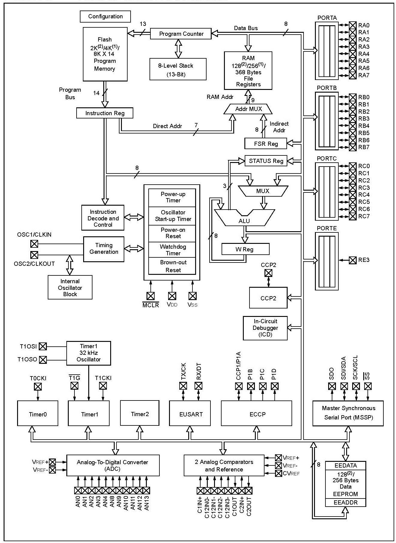
BLOCK DIAGRAM PIC16F886
The internal block diagram of PIC16F886 is given below:
PIC16F886 Applications
- It is used in most small home-based projects.
- PIC16F886 also comes in some commercial items due to its multiple functionalities within a single controller.
- To control the motor speed PIC16F886 is also used.
- Most of the coffee machines and vending machines also use PIC16F886.
PIC16F886 Programming
To start learning pic microcontroller programming, you should have a grasp on GPIO pins. Therefore, we have elaborated on all pins and their functions in previous sections. We can use either assembly language or c programming to program microcontrollers. We suggest you have a look on these getting started tutorials:
- pic microcontroller assembly language programming
- Pic microcontroller programming in c using Mikroc Pro for PIC
Tools for Programming
To start with programming you need the following software and hardware components:
- A compiler or IDE to write a program in assembly or C language: The main thing where you will type your first microcontroller program is a compiler or integrated development environment. The three most popular compilers used for pic microcontroller programming are MPLABX IDE, Mikro C for PIC and PIC CCS compiler. A compiler is used to generate a hex file that the user uploads to a microcontroller.
- Programmer or Burner: When you finish writing your code, you have a hex file that you want to upload to a microcontroller. We use a programmer or burner to upload binary files to pic16f866. Pickit3 is one of the best choices for code burning.
- Pic Development Boards: Development boards are optional but they make your development process very easy. Because they offer man on-board peripherals like GPIO connectors, Sensors, ADCs, etc.
We will update this section with programming examples in embedded C language in this section.