This PWM tutorial for the MSP430 LaunchPad shows you how to generate Pulse Width Modulation signals with the MSP430G2553 microcontroller using the Energia IDE, and how to use PWM to control the brightness of an LED with a potentiometer. PWM is one of the most versatile peripherals on any microcontroller — it is the technique behind LED dimming, DC motor speed control, servo positioning, buzzer tone generation, class-D audio amplification, and switching power supplies. If you master analogWrite() on the MSP430G2 LaunchPad, you have unlocked a huge range of real-world embedded applications.
In this guide we explain what PWM is, how duty cycle and frequency define the output waveform, which specific pins on the MSP430G2 LaunchPad can generate hardware PWM, and walk through a complete working project: reading a potentiometer with the ADC and using its value to smoothly adjust the brightness of an LED through PWM. By the end you will understand exactly how the analogWrite() function translates an 8-bit duty value into a real digital pulse train on the MSP430.
This is the eighth tutorial in our MSP430G2 LaunchPad series. If you haven’t worked through the earlier tutorials, start with the basics first — especially GPIO and ADC, both of which this PWM project builds directly on:
- MSP430G2 LaunchPad Getting Started Tutorial with Energia IDE
- MSP430G2 LaunchPad GPIO Tutorial – Input/Output Pins
- How to Use ADC of MSP430 Microcontroller
Related PWM tutorials on other microcontrollers and applications:
- SPWM Generation using PIC Microcontroller
- PWM Generation using PIC Microcontroller
- DC Motor Speed Control with PWM
- DC Motor Speed Control with Bluetooth
What You Will Learn
- What Pulse Width Modulation is, in plain language and with real examples
- The three parameters that define any PWM waveform — period, frequency, and duty cycle
- How duty cycle controls the effective average voltage seen by a load (LED, motor, heater)
- The two ways to generate PWM — analog comparator circuits vs digital timer peripherals inside an MCU
- Which specific header pins on the MSP430G2 LaunchPad support hardware PWM
- How Energia’s
analogWrite()function maps an 8-bit value (0–255) onto a real duty cycle - A complete circuit and code example: reading a potentiometer on A7 and using it to dim an LED via PWM
- The
map()function trick for bridging 10-bit ADC readings to 8-bit PWM values cleanly - Common PWM troubleshooting — no output, flickering, dim LED at 255, and the current-drive limit
Prerequisites and Required Components
- MSP430G2 LaunchPad (MSP430G2553)
- 1 × LED (any color)
- 1 × 220 Ω resistor (current-limiting for the LED)
- 1 × 10 kΩ potentiometer (provides variable voltage for the ADC input)
- Breadboard and jumper wires
- Oscilloscope (optional — lets you actually see the PWM waveform; if you don’t have one, the LED brightness change is enough for this tutorial)
- Energia IDE installed and configured
What is Pulse Width Modulation (PWM)?
Pulse Width Modulation is a digital technique for approximating an analog output using a fast train of on/off pulses. The pin is either fully HIGH (3.3 V on the MSP430) or fully LOW (0 V) — never in between — but by varying the ratio of how long it spends HIGH versus LOW, you can simulate any average voltage between the two rails.
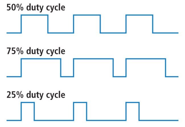
For example, if the pulse train period is 20 ms (a frequency of 50 Hz) and the pin stays HIGH for 10 ms and LOW for 10 ms, the effective average voltage is 1.65 V (half of 3.3 V). That’s called a 50% duty cycle. If the HIGH time is 15 ms and LOW time is 5 ms, the average voltage is 2.475 V — a 75% duty cycle. By changing just the HIGH time, you smoothly sweep the effective voltage from 0 V (duty = 0%) all the way to 3.3 V (duty = 100%).
PWM signals can be generated two ways:
- Analog circuits: a triangle-wave generator compared against a DC reference with an op-amp produces a PWM signal. This is how old-school dimmers and motor controllers worked.
- Digital microcontrollers: a hardware timer counts up, compares the count to a programmable value, and toggles an output pin accordingly. This is how the MSP430G2553 (and every other modern MCU) generates PWM — in silicon, at very high precision, with near-zero CPU involvement.
If you want a deeper dive into PWM theory, see our PWM introduction article. For now, the three parameters you need to understand are period, duty cycle, and frequency.
Period, Duty Cycle, and Frequency Explained
Period is the total time of one full PWM cycle — the HIGH portion plus the LOW portion:
Period = ON time + OFF time
Duty cycle is the fraction of the period spent HIGH, expressed as a percentage. It is the most important PWM parameter — it is what actually controls the effective output level:
Duty cycle = ON time / Period
           = ON time / (ON time + OFF time)
A duty cycle of 0% means the pin is always LOW (LED off, motor stopped); 100% means always HIGH (LED at full brightness, motor at full speed); 50% means half the time HIGH and half LOW. Between 0 and 100% you get every level in between.
Frequency is how many complete PWM cycles occur per second. Frequency and period are reciprocals:
Frequency = 1 / Period
For LED dimming you want a frequency well above the human eye’s flicker threshold (~60 Hz) to avoid visible flickering — 500 Hz to several kHz is typical. For DC motor control, frequencies in the 1–20 kHz range are standard (low enough for the motor to respond, high enough to be inaudible). Energia’s default PWM frequency on the MSP430G2 LaunchPad is around 490 Hz, which is fine for LEDs and most servos.
Which MSP430G2 LaunchPad Pins Support Hardware PWM?
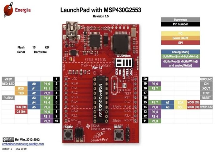
Not every pin on the MSP430G2 LaunchPad can generate PWM. Only the pins connected to Timer_A’s compare outputs support hardware PWM through analogWrite(). On the MSP430G2553 (the chip on the standard MSP430G2 LaunchPad), these pins are:
| LaunchPad Header Pin | MSP430G2553 Pin | Timer Output |
|---|---|---|
| 4 | P1.2 | TA0.1 |
| 9 | P2.1 | TA1.1 |
| 10 | P2.2 | TA1.1 |
| 12 | P2.4 | TA1.2 |
| 13 | P2.5 | TA1.2 |
| 14 | P1.6 | TA0.1 |
| 19 | P2.7 | TA0.1 |
On the standard MSP430G2 LaunchPad pin map diagram these pins are color-coded (they are often shown in purple or a separate color from regular GPIO), so you can identify them at a glance.
Important: if you call analogWrite() on a pin that does not support hardware PWM, Energia silently falls back to on/off digital output (the pin will be either fully HIGH for values > 127 or fully LOW for values ≤ 127), with no actual PWM modulation. If your LED refuses to dim, verify that you’re using one of the PWM-capable pins listed above.
Another critical limitation: the MSP430G2553’s GPIO pins can only source about 6 mA each, much lower than an Arduino. That is enough to drive an LED directly (with a 220 Ω current-limiting resistor), but nowhere near enough to drive a DC motor, a large relay, or a high-power LED. For anything drawing more than ~6 mA, use a transistor (2N2222, BC547) or a MOSFET (IRLZ44N, AO3400) to switch the load, with the PWM signal driving the transistor’s base or gate.
Circuit Diagram for PWM LED Dimming with MSP430

The circuit is straightforward — a potentiometer on the ADC input, an LED on a PWM output:
- Potentiometer outer pin 1 → 3.3 V
- Potentiometer outer pin 2 → GND
- Potentiometer wiper → LaunchPad header pin 15 (A7 / P1.7)
- LED anode → LaunchPad header pin 4 (P1.2 = PWM) via 220 Ω resistor
- LED cathode → LaunchPad GND
When you rotate the potentiometer, the voltage on A7 sweeps from 0 V to 3.3 V. Our code reads this voltage with the ADC, maps it to a PWM duty cycle, and feeds that to the LED pin. The LED smoothly dims from fully off to fully bright as you rotate the knob.
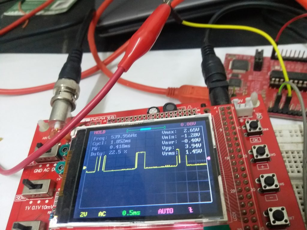
If you want to see the actual waveform instead of just the LED brightness, connect an oscilloscope probe to header pin 4 and the probe ground to GND. You will see a 3.3 V peak-to-peak square wave whose duty cycle changes as you turn the knob.
PWM Programming with MSP430 Microcontroller (Energia)
Energia exposes hardware PWM through the Arduino-compatible analogWrite() function. You don’t need to configure timer registers, clock dividers, or compare units — just call one function with two arguments.
The analogWrite() Function
analogWrite(pin, value) sets the PWM duty cycle on the specified pin. The value is 8-bit: 0 to 255, where 0 = 0% duty (always off) and 255 = 100% duty (always on). 127 is approximately 50% duty cycle.
- First argument: the header pin number. Must be one of the PWM-capable pins (4, 9, 10, 12, 13, 14, or 19 on the MSP430G2 LaunchPad).
- Second argument: the 8-bit duty cycle value (0–255). The MSP430’s hardware PWM is actually higher-resolution than 8-bit, but Energia’s API normalizes it to 8-bit for Arduino compatibility.
Example: to drive header pin 4 at 50% duty cycle:
analogWrite(4, 127); // ~50% duty cycle on header pin 4 (P1.2)You still need to configure the pin as an output with pinMode() in setup() — otherwise Energia’s default input mode will block the timer from driving the pin.
Controlling LED Brightness with PWM and a Potentiometer
Now let’s put the full example together. The sketch reads the potentiometer’s voltage from ADC channel A7, maps the 10-bit ADC reading (0–1023) to an 8-bit PWM value (0–255), and writes that to the LED pin.
First, declare the PWM pin and potentiometer pin with descriptive names:
const int pinNumber = 4;   // header pin 4 (P1.2) — PWM capable
const int potPin    = A7;  // header pin 15 — ADC channel A7
int ADCval;                // raw 10-bit ADC reading (0..1023)
int duty_cycle;            // 8-bit PWM value (0..255)
Inside setup(), configure the PWM pin as an output. The ADC pin doesn’t need pinMode() — analogRead() handles pin configuration internally.
void setup()
{
  pinMode(pinNumber, OUTPUT);   // PWM pin must be an output
}
Inside loop(), read the potentiometer voltage, scale it to 8 bits, and write it to the PWM pin:
void loop()
{
  ADCval = analogRead(potPin);               // 0..1023
  duty_cycle = map(ADCval, 0, 1023, 0, 255); // scale to 0..255
  analogWrite(pinNumber, duty_cycle);        // generate PWM
}
The map() function is the clean way to convert between ranges. map(ADCval, 0, 1023, 0, 255) reads: “take ADCval, which ranges from 0 to 1023, and scale it proportionally to a range of 0 to 255.” Turn the potentiometer to zero → ADC returns 0 → map gives 0 → analogWrite(4, 0) → LED off. Turn the potentiometer all the way up → ADC returns 1023 → map gives 255 → analogWrite(4, 255) → LED at full brightness.
Complete Code for MSP430 PWM LED Brightness Control
const int pinNumber = 4;   // header pin 4 (P1.2) — PWM output to LED
const int potPin    = A7;  // header pin 15 — potentiometer wiper

int ADCval;
int duty_cycle;

void setup()
{
  pinMode(pinNumber, OUTPUT);   // PWM pin must be an output
}

void loop()
{
  ADCval = analogRead(potPin);                // read pot: 0..1023
  duty_cycle = map(ADCval, 0, 1023, 0, 255);  // scale to PWM range
  analogWrite(pinNumber, duty_cycle);         // drive LED
  delay(10);                                  // small settle time
}
Upload the sketch. Rotate the potentiometer — the LED smoothly dims from off to full brightness and back. If you have an oscilloscope, connect it to header pin 4 and watch the duty cycle change in real time as you turn the knob.
Common PWM Applications on the MSP430
- LED dimming — the example above, but you can also fade an LED in and out by sweeping the duty cycle in a
forloop. - RGB LED color mixing — drive three PWM pins, one per color channel, to produce any color in the visible spectrum. See the RGB LED Interfacing with MSP430G2 LaunchPad tutorial for the full code.
- DC motor speed control — feed the PWM signal into a MOSFET or H-bridge driver (L293D, DRV8833) that switches a real motor. Duty cycle controls motor speed.
- Servo motor control — hobby servos expect a 50 Hz PWM with 1–2 ms pulse widths. Use the
Servolibrary in Energia, which handles the precise timing automatically. - Buzzer / piezo tone generation — drive a PWM pin at an audible frequency (500 Hz – 2 kHz) to make a buzzer beep. Use the
tone()function for musical notes. - Switching power supplies — PWM drives a MOSFET + inductor + diode + capacitor network to produce a regulated output at a fixed voltage. Higher frequencies (100 kHz+) need the MSP430’s timer configured directly, past what
analogWrite()offers.
Troubleshooting MSP430 PWM Issues
- LED stays fully on or fully off, no dimming. You picked a pin that doesn’t support hardware PWM. Move the LED to one of the PWM-capable pins: 4, 9, 10, 12, 13, 14, or 19.
- LED flickers visibly at low brightness. PWM frequency is too low. Energia’s default on MSP430G2 is around 490 Hz, which is usually fine for LEDs but can be visible in peripheral vision. For flicker-free operation, configure the timer directly or use a different PWM pin that maps to a faster timer.
- LED brightness doesn’t change when I turn the potentiometer. Either the potentiometer is miswired (wiper must go to the ADC pin, outer pins to 3.3 V and GND), the ADC is reading a floating pin, or you used
analogWrite(pin, 255)accidentally somewhere and never update it. - LED at full brightness even at duty cycle = 0. The wiring is inverted — you wired the LED between the PWM pin and 3.3 V instead of between the PWM pin and GND. Flip the LED so the anode goes to the PWM pin and the cathode (short leg) to GND.
- LED looks dim even at duty cycle = 255. The current-limiting resistor is too large. Try 220 Ω. Also verify that you’re not pushing the MSP430 past its 6 mA per-pin limit — the LED should be visibly lit at full duty.
- MSP430 gets hot after running PWM. You are drawing too much current from a pin, probably driving a motor or large LED directly. Put a transistor or MOSFET between the MSP430 pin and the load — the MCU should only drive the gate/base, not the load itself.
- Code compiles but no output on the scope.
pinMode(pin, OUTPUT)is missing, or the pin number is wrong. Double-check the PWM pin table above and confirmpinMode()is set insetup().
Frequently Asked Questions
Which pins support PWM on the MSP430G2 LaunchPad?
Seven pins support hardware PWM on the standard MSP430G2 LaunchPad with the MSP430G2553: header pins 4, 9, 10, 12, 13, 14, and 19. These correspond to MSP430 pins P1.2, P2.1, P2.2, P2.4, P2.5, P1.6, and P2.7 respectively, all of which are tied to the Timer_A compare outputs.
What is the PWM frequency on the MSP430G2 LaunchPad by default?
Energia uses roughly 490 Hz as the default PWM frequency on MSP430G2 LaunchPad PWM pins — close to the 490 Hz Arduino default, which keeps sketches portable. 490 Hz is fine for LED dimming, motor speed control, and most servo applications. For higher frequencies (audio, DC-DC converters, etc.) you have to configure the Timer_A registers directly instead of using analogWrite().
What’s the resolution of the MSP430G2 hardware PWM?
The MSP430G2553’s Timer_A hardware supports 16-bit PWM natively, but Energia’s analogWrite() API is 8-bit (0–255) to match Arduino. If you need higher resolution (say for precise motor control or LED fading), configure the timer registers directly — the MSP430G2553 datasheet documents this in the Timer_A chapter.
Can I control a DC motor directly from an MSP430 PWM pin?
No. MSP430G2 pins can only source about 6 mA, while even the smallest DC motor needs several hundred milliamps at startup. You must drive the motor through a transistor, MOSFET, or motor driver IC (L293D, DRV8833, TB6612FNG) — the MSP430 PWM signal controls the gate/base of the driver, and the driver handles the motor current from a separate power supply.
How do I fade an LED in and out smoothly?
Sweep the duty cycle in a for loop with a short delay:
void loop() {
  for (int d = 0; d <= 255; d++) { analogWrite(4, d); delay(5); }  // fade in
  for (int d = 255; d >= 0; d--) { analogWrite(4, d); delay(5); }  // fade out
}
The 5 ms delay gives a ~2.5-second fade from off to full brightness and back. Shorter delays give faster fades.
Why does the LED look about the same brightness at duty cycle 200 and 255?
Human eye perception of brightness is logarithmic, not linear — the difference between 200 and 255 on an 8-bit PWM scale is visually much smaller than the difference between 20 and 75. For a perceptually linear fade, apply a gamma correction in software: use pow(value / 255.0, 2.2) * 255 before writing to the PWM pin.
Conclusion
You now know how to generate PWM with the MSP430 microcontroller and control the brightness of an LED with a potentiometer — combining the ADC input and PWM output into a single working project. You learned what PWM is, how duty cycle and frequency shape the waveform, which pins on the MSP430G2 LaunchPad support hardware PWM, and how Energia’s analogWrite() function makes PWM as simple as digitalWrite(). The same technique scales up to DC motor speed control, servo positioning, RGB LED color mixing, buzzer tone generation, and many more applications. This concludes the current MSP430G2 series — you now have GPIO, ADC, UART, LCD, and PWM under your belt, which is enough to build a huge range of real embedded projects.
Related MSP430G2 LaunchPad Tutorials
- MSP430G2 LaunchPad Getting Started Tutorial with Energia IDE
- MSP430G2 LaunchPad GPIO Tutorial – Input/Output Pins
- RGB LED Interfacing with MSP430G2 LaunchPad
- PIR Motion Sensor Interfacing with MSP430G2 LaunchPad
- 16×2 LCD Interfacing with MSP430 LaunchPad
- Scrolling Text on LCD using MSP430 Microcontroller
- UART Serial Communication with MSP430 Microcontroller
- How to Use ADC of MSP430 Microcontroller
what is the frequency of the generated PWM signal.