In this tutorial, we will learn to interface SSD1306 OLED with STM32 Nucleo and program it using STM32CubeIDE and HAL libraries. An OLED (organic light-emitting diode) is used frequently in displaying texts, bitmap images, shapes, and different types of clocks. They offer good view angles and pixel density in a cost-effective manner. At first, we will take a look at the 0.96-inch OLED display, its pinout, connections with the STM32 board, and then use STMCube IDE to program our module to display different texts on the OLED display.

SSD1306 0.96 inch OLED Display
OLED stands for organic light-emitting diode. Its name shows that it is a flat light emitting technology that is developed when two organic thin films are connected in series between two electric conductors. When an electric current is supplied to these conductors then the organic compound is made which emits the bright light. Typically, one conductor is the transparent conductor between these two conductors therefore there is no need for any backlight to emits the light. Therefore, this OLED display has improved image quality, full viewing angle, high brightness, better contrast, wide color range, low power consumption, more efficient and reliable as compared to a simple LCD display. It is mainly used in digital display devices such as computer monitors, mobile phones, handheld games, and televisions screens, etc.
Although there are several types of OLED displays available in the market the one which we will be using is the SSD1306 0.96-inch OLED display. The main component of all different types of OLED displays is an SSD1306 controller which uses I2C or SPI protocol to communicate with the microcontrollers. The OLED performs faster in SPI communication but it is popular with I2C communication. The reason for the popularity is the lower number of pins. The OLED displays can vary in size, color, and shape but are primarily programmed in a similar way.
Let us take a look at the OLED display which we will be using in this article. It is called SSD1306 0.96-inch OLED display which has 128×64 pixels and communicates only via I2C protocol with the development boards. It is cheap and readily available in the market.
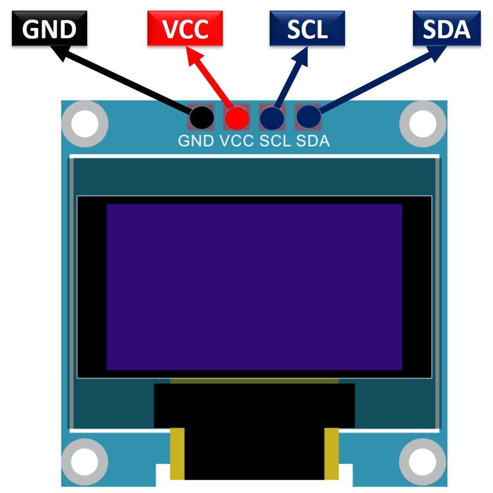
Below you can see the pinout of this OLED Display.
Recommended Reading: Monochrome 0.96” OLED Display
SSD1306 OLED Pinout
There are four pins in this display. Imprinted as VCC, GND, SCL, and SDA respectively. The VCC and GND pins will power the OLED display and will be connected with the STM32 power supply pins as they require a driving voltage of 3.3-5V. The SCL and SDA pins are necessary for generating the clock signal and in the transmission of data respectively. Both of these pins will be connected with the I2C pins of the STM32 board.
Now let us have a look at the specifications for this model:
| Size | 0.96 inch |
| Terminals | 4 |
| Pixels | 128×64 |
| Communication | I2C only |
| VCC | 3.3V-5V |
| Operating Temperature | -40℃ to +80℃ |
Interfacing SSD1306 OLED Display with STM32 Nucleo
For this project we will require the following components:
- STM32 Nucleo
- SSD1306 OLED
- Connecting Wires
- Breadboard
As we have seen above, the OLED display has 4 terminals which we will connect with the STM32 Nucleo board. As the OLED display requires an operating voltage in the range of 3.3-5V, we will connect the VCC terminal with 5V which will be in common with the Nucleo board. The SCL and SDA pins of the OLED will be connected with the I2C1 SDA and SCL pins of the STM32 board respectively. PB7 is I2C1_SDA pin and PB6 is I2C1_SCL pin. Moreover, the grounds will be in common.
The connections between the two devices can be seen below.
| STM32 Nucleo | SSD1306 OLED Display |
|---|---|
| 5V | VCC |
| PB7 | SDA |
| PB6 | SCL |
| GND | GND |

OLED with STM32 Nucleo Code
We will use STM32Cube IDE to program our STM32 board. Open the IDE and head over to a new project.
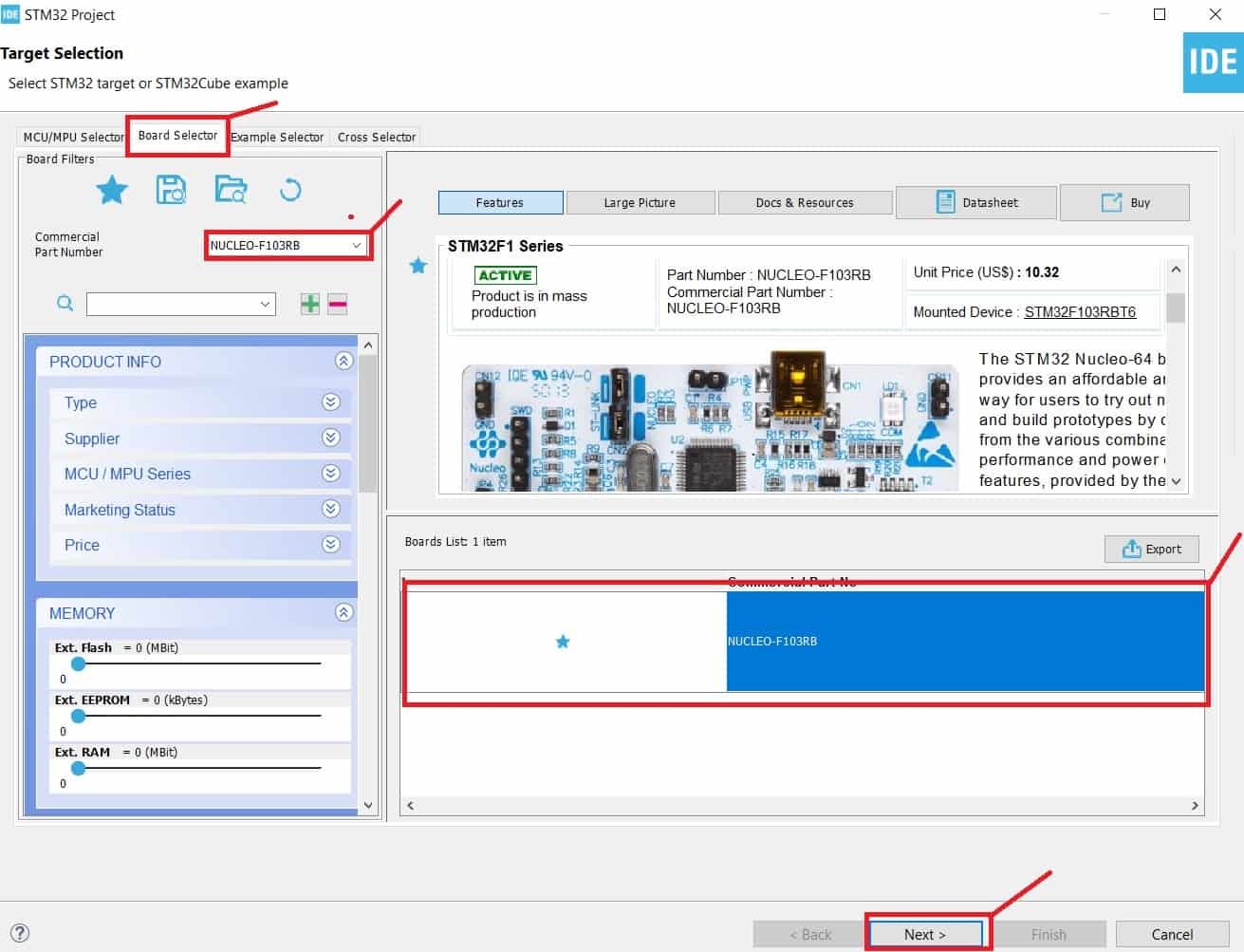
Then for the target selection, specify the STM32 Nucleo board number. After that click on any column as shown in the picture below. Then click the ‘Next’ button.
Specify the name of your project then click ‘Finish’ to complete the setup of your project.
Now go to System Core > RCC then select ‘Crystal/Ceramic Resonator’ in from the High Speed Clock feature.

Now we have enabled the RCC external clock source.
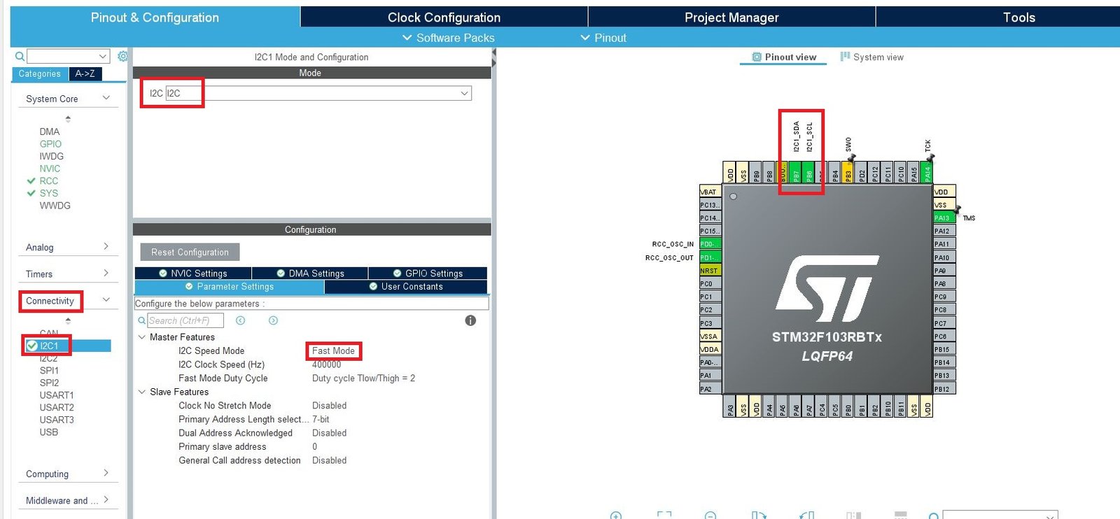
Now head over to Connectivity > I2C1. Select the I2C mode as ‘I2C.’ Then go to ‘Parameter Settings’ and set the I2C speed mode as ‘Fast Mode.’ This is necessary for the SSD1306 OLED.
Clock Configuration
Next, go to the Clock Configuration found at the top. This will open the following window. Here we will select the clock frequency.
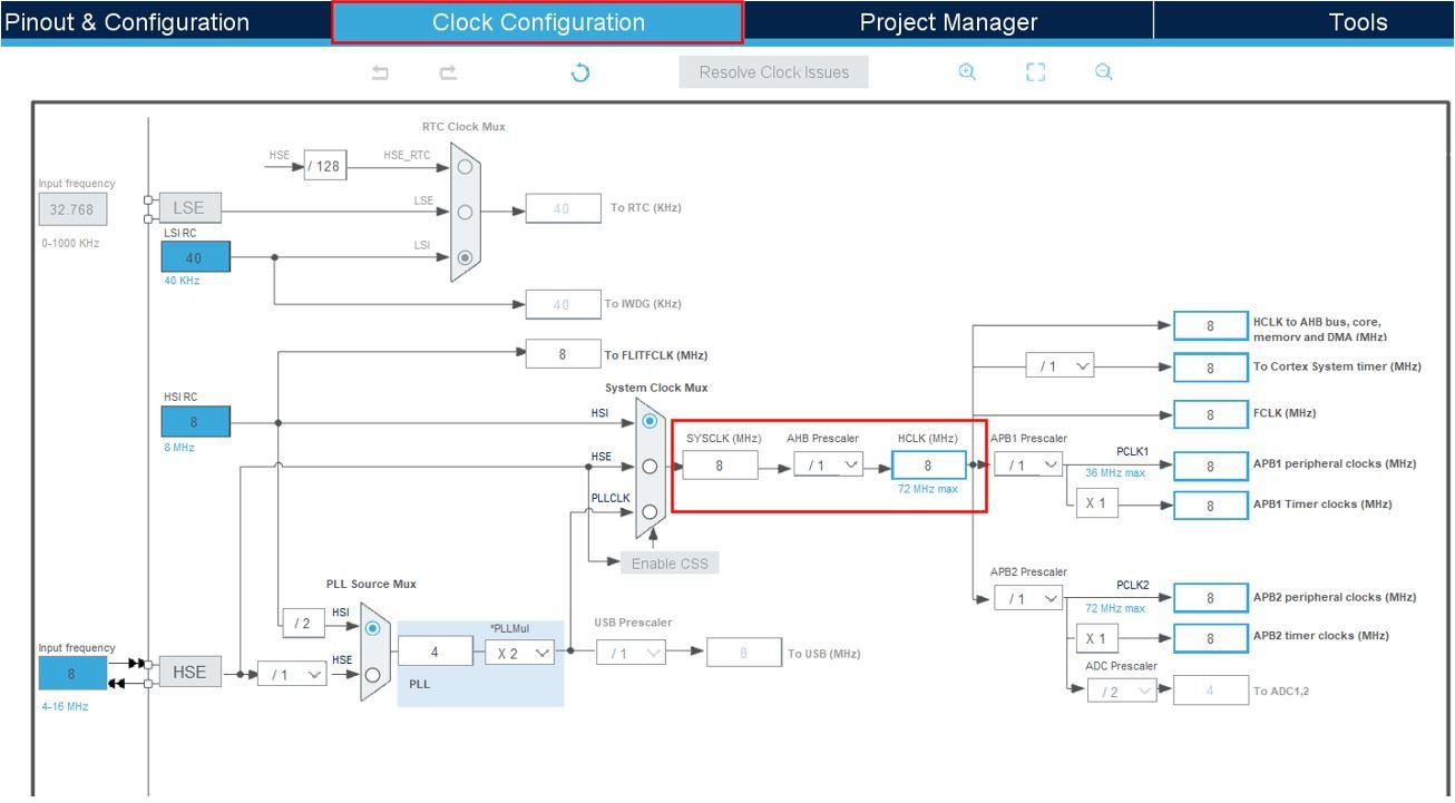
You can specify your system clock. We will set it as 72 MHz. These are the configurations we have set:

Now we will save our file. Press Ctrl + S. The following window will appear. Click ‘Yes.’ This will generate a template code for you.

Another window will appear that will ask if you want to open the perspective. Click ‘Yes.’

STM32 OLED HAL Library
As we are working with an SSD1306 OLED with our STM32 Nucleo, we will require the ssd1306.h and fonts.h libraries. These libraries will be used to access different functions that will enable us to display texts and numbers on the OLED in various ways.
ssd1306.h
Go to Core > Inc and create a new file called ‘ssd1306.h‘ Copy the following code from this link and save it to this file.
In ssd1306.h file, remove #include “i2c.h” (line 49) and add extern I2C_HandleTypeDef hi2c1;
fonts.h
Go to Core > Inc and create a new file called ‘fonts.h‘ Copy the following code from this link and save it to this file.
ssd1306.c
Similarly, head over to Core > Src and create a new file called ‘ssd1306.c‘ Copy the following code from this link and save it to this file.
fonts.c
Head over to Core > Src and create a new file called ‘fonts.c‘ Copy the following code from this link and save it to this file.
STM32 Nucleo OLED Code
We will use the ssd1306 library functions to display text and numbers on the OLED in different fonts.
Now let us look at our main.c file that was generated. Inside the main.c file, make sure the following code is part of your script by including the lines of code given below.
#include "main.h"

#include "fonts.h"
#include "ssd1306.h"

extern I2C_HandleTypeDef hi2c1;

void SystemClock_Config(void);
static void MX_GPIO_Init(void);
static void MX_I2C1_Init(void);

int main(void)
{
  HAL_Init();
  SystemClock_Config();
  MX_GPIO_Init();
  MX_I2C1_Init();

  SSD1306_Init();
   char string[5];

   SSD1306_GotoXY (0,0);
   SSD1306_Puts ("SSD1306", &Font_11x18, 1);
   SSD1306_GotoXY (0, 30);
   SSD1306_Puts ("OLED DEMO", &Font_11x18, 1);
   SSD1306_UpdateScreen();
   HAL_Delay (1000);

   SSD1306_Fill(0); //clear oled

   SSD1306_Clear();
   SSD1306_GotoXY (30,0);
   SSD1306_Puts ("COUNTER", &Font_11x18, 1);

  while (1)
  {
		for (int num=1;num<=1000;num++)
		{
			itoa(num,string, 10);
			SSD1306_GotoXY (0, 30);
			SSD1306_Puts ("             ", &Font_16x26, 1);
			SSD1306_UpdateScreen();
			if(num<10) {
				SSD1306_GotoXY (53, 30);  // 1 DIGIT
			}
			else if (num<100) {
				SSD1306_GotoXY (45, 30);  // 2 DIGITS
			}
			else  {
				SSD1306_GotoXY (37, 30);  // 3 DIGITS
			}
			SSD1306_Puts (string, &Font_16x26, 1);
			SSD1306_UpdateScreen();
			HAL_Delay (500);
		}

  }

}
Working of the Code
We start off by including fonts.h and ssd1306.h libraries.
#include "fonts.h"
#include "ssd1306.h"
Inside the main function, first all the peripherals are initialized, system clock is configured and all the configured peripherals are initialized.
  HAL_Init();
  SystemClock_Config();
  MX_GPIO_Init();
  MX_I2C1_Init();
The first step is to initialize the OLED. We use the SSD1306_Init() function for initialization.
SSD1306_Init();Next we will set the x and the y axis position from where the text should start. SSD1306_gotoXY() function is used to set the write pointers. We have passed (0,0) as the parameter hence the text starts from the upper left corner. The first parameter is the x-axis position that (+x) increases towards the right. The second parameter is the y-axis position that (+y) increases downwards.
SSD1306_GotoXY (0,0);After setting the starting x-axis and y-axis positions, we will write the text on the OLED using the function SSD1306_Puts(). This function takes in three parameters which is the string to be displayed, the font name and the color of the text. We want to display the text ‘SSD1306’ in Font_11x18 and in white color.
SSD1306_Puts ("SSD1306", &Font_11x18, 1);Similarly, we will set the x and y axis position at (0,30) and print the text ‘OLED DEMO’ in the same font and color. Call SSD1306_UpdateScreen() to display the texts.
   SSD1306_GotoXY (0, 30);
   SSD1306_Puts ("OLED DEMO", &Font_11x18, 1);
   SSD1306_UpdateScreen();
   HAL_Delay (1000);
After that we will clear the screen.
SSD1306_Clear();
SSD1306_Fill(0); //clear oled
Next, we will set the x and y axis position at (30, 0) and print the text ‘COUNTER’ in Font_11x18 and white color. We aim to display numbers from 0-1000 under the ‘COUNTER’ text. These numbers will be center aligned and will update to a new number after every second. This will be accomplished by using a for loop that runs for 1000 iterations within the infinite while loop. The starting x and y-axis positions will be changed accordingly so the numbers are displayed in the center of the screen.
SSD1306_GotoXY (30,0);
SSD1306_Puts ("COUNTER", &Font_11x18, 1);

  while (1)
  {
		for (int num=1;num<=1000;num++)
		{
			itoa(num,string, 10);
			SSD1306_GotoXY (0, 30);
			SSD1306_Puts ("             ", &Font_16x26, 1);
			SSD1306_UpdateScreen();
			if(num<10) {
				SSD1306_GotoXY (53, 30);  // 1 DIGIT
			}
			else if (num<100) {
				SSD1306_GotoXY (45, 30);  // 2 DIGITS
			}
			else  {
				SSD1306_GotoXY (37, 30);  // 3 DIGITS
			}
			SSD1306_Puts (string, &Font_16x26, 1);
			SSD1306_UpdateScreen();
			HAL_Delay (500);
		}

  }
main.c file
This is how a complete main.c file will be after modification.
/* USER CODE BEGIN Header */
/**
  ******************************************************************************
  * @file           : main.c
  * @brief          : Main program body
  ******************************************************************************
  * @attention
  *
  * Copyright (c) 2024 STMicroelectronics.
  * All rights reserved.
  *
  * This software is licensed under terms that can be found in the LICENSE file
  * in the root directory of this software component.
  * If no LICENSE file comes with this software, it is provided AS-IS.
  *
  ******************************************************************************
  */
/* USER CODE END Header */
/* Includes ------------------------------------------------------------------*/
#include "main.h"

/* Private includes ----------------------------------------------------------*/
/* USER CODE BEGIN Includes */
extern I2C_HandleTypeDef hi2c1;
#include "fonts.h"
#include "ssd1306.h"
#include <stdio.h>
/* USER CODE END Includes */

/* Private typedef -----------------------------------------------------------*/
/* USER CODE BEGIN PTD */


/* USER CODE END PTD */

/* Private define ------------------------------------------------------------*/
/* USER CODE BEGIN PD */

/* USER CODE END PD */

/* Private macro -------------------------------------------------------------*/
/* USER CODE BEGIN PM */

/* USER CODE END PM */

/* Private variables ---------------------------------------------------------*/
I2C_HandleTypeDef hi2c1;

/* USER CODE BEGIN PV */

/* USER CODE END PV */

/* Private function prototypes -----------------------------------------------*/
void SystemClock_Config(void);
static void MX_GPIO_Init(void);
static void MX_I2C1_Init(void);
/* USER CODE BEGIN PFP */

/* USER CODE END PFP */

/* Private user code ---------------------------------------------------------*/
/* USER CODE BEGIN 0 */

/* USER CODE END 0 */

/**
  * @brief  The application entry point.
  * @retval int
  */
int main(void)
{
  /* USER CODE BEGIN 1 */

  /* USER CODE END 1 */

  /* MCU Configuration--------------------------------------------------------*/

  /* Reset of all peripherals, Initializes the Flash interface and the Systick. */
  HAL_Init();

  /* USER CODE BEGIN Init */

  /* USER CODE END Init */

  /* Configure the system clock */
  SystemClock_Config();

  /* USER CODE BEGIN SysInit */

  /* USER CODE END SysInit */

  /* Initialize all configured peripherals */
  MX_GPIO_Init();
  MX_I2C1_Init();
  /* USER CODE BEGIN 2 */
  uint8_t res = SSD1306_Init();
  	printf("OLED init: %d\n", res);
  	SSD1306_GotoXY (0,0);
  	   SSD1306_Puts ("SSD1306", &Font_11x18, 1);
  	   SSD1306_GotoXY (0, 30);
  	   SSD1306_Puts ("OLED DEMO", &Font_11x18, 1);
  	   SSD1306_UpdateScreen();
  	   HAL_Delay (1000);
		SSD1306_Fill(0); //clear oled


  	   SSD1306_GotoXY (30,0);
  	   SSD1306_Puts ("COUNTER", &Font_11x18, 1);
  	HAL_Delay(1000);
    char string[5];
  /* USER CODE END 2 */

  /* Infinite loop */
  /* USER CODE BEGIN WHILE */
  while (1)
  {
	  for (int num=1;num<=1000;num++)
	  		{
	  			itoa(num,string, 10);
	  			SSD1306_GotoXY (0, 30);
	  			SSD1306_Puts ("             ", &Font_16x26, 1);
	  			SSD1306_UpdateScreen();
	  			if(num<10) {
	  				SSD1306_GotoXY (53, 30);  // 1 DIGIT
	  			}
	  			else if (num<100) {
	  				SSD1306_GotoXY (45, 30);  // 2 DIGITS
	  			}
	  			else  {
	  				SSD1306_GotoXY (37, 30);  // 3 DIGITS
	  			}
	  			SSD1306_Puts (string, &Font_16x26, 1);
	  			SSD1306_UpdateScreen();
	  			HAL_Delay (500);

	  		}
    /* USER CODE END WHILE */

    /* USER CODE BEGIN 3 */
  }
  /* USER CODE END 3 */
}

/**
  * @brief System Clock Configuration
  * @retval None
  */
void SystemClock_Config(void)
{
  RCC_OscInitTypeDef RCC_OscInitStruct = {0};
  RCC_ClkInitTypeDef RCC_ClkInitStruct = {0};

  /** Initializes the RCC Oscillators according to the specified parameters
  * in the RCC_OscInitTypeDef structure.
  */
  RCC_OscInitStruct.OscillatorType = RCC_OSCILLATORTYPE_HSE;
  RCC_OscInitStruct.HSEState = RCC_HSE_ON;
  RCC_OscInitStruct.HSEPredivValue = RCC_HSE_PREDIV_DIV1;
  RCC_OscInitStruct.HSIState = RCC_HSI_ON;
  RCC_OscInitStruct.PLL.PLLState = RCC_PLL_ON;
  RCC_OscInitStruct.PLL.PLLSource = RCC_PLLSOURCE_HSE;
  RCC_OscInitStruct.PLL.PLLMUL = RCC_PLL_MUL9;
  if (HAL_RCC_OscConfig(&RCC_OscInitStruct) != HAL_OK)
  {
    Error_Handler();
  }

  /** Initializes the CPU, AHB and APB buses clocks
  */
  RCC_ClkInitStruct.ClockType = RCC_CLOCKTYPE_HCLK|RCC_CLOCKTYPE_SYSCLK
                              |RCC_CLOCKTYPE_PCLK1|RCC_CLOCKTYPE_PCLK2;
  RCC_ClkInitStruct.SYSCLKSource = RCC_SYSCLKSOURCE_PLLCLK;
  RCC_ClkInitStruct.AHBCLKDivider = RCC_SYSCLK_DIV1;
  RCC_ClkInitStruct.APB1CLKDivider = RCC_HCLK_DIV2;
  RCC_ClkInitStruct.APB2CLKDivider = RCC_HCLK_DIV1;

  if (HAL_RCC_ClockConfig(&RCC_ClkInitStruct, FLASH_LATENCY_2) != HAL_OK)
  {
    Error_Handler();
  }
}

/**
  * @brief I2C1 Initialization Function
  * @param None
  * @retval None
  */
static void MX_I2C1_Init(void)
{

  /* USER CODE BEGIN I2C1_Init 0 */

  /* USER CODE END I2C1_Init 0 */

  /* USER CODE BEGIN I2C1_Init 1 */

  /* USER CODE END I2C1_Init 1 */
  hi2c1.Instance = I2C1;
  hi2c1.Init.ClockSpeed = 400000;
  hi2c1.Init.DutyCycle = I2C_DUTYCYCLE_2;
  hi2c1.Init.OwnAddress1 = 0;
  hi2c1.Init.AddressingMode = I2C_ADDRESSINGMODE_7BIT;
  hi2c1.Init.DualAddressMode = I2C_DUALADDRESS_DISABLE;
  hi2c1.Init.OwnAddress2 = 0;
  hi2c1.Init.GeneralCallMode = I2C_GENERALCALL_DISABLE;
  hi2c1.Init.NoStretchMode = I2C_NOSTRETCH_DISABLE;
  if (HAL_I2C_Init(&hi2c1) != HAL_OK)
  {
    Error_Handler();
  }
  /* USER CODE BEGIN I2C1_Init 2 */

  /* USER CODE END I2C1_Init 2 */

}

/**
  * @brief GPIO Initialization Function
  * @param None
  * @retval None
  */
static void MX_GPIO_Init(void)
{
/* USER CODE BEGIN MX_GPIO_Init_1 */
/* USER CODE END MX_GPIO_Init_1 */

  /* GPIO Ports Clock Enable */
  __HAL_RCC_GPIOD_CLK_ENABLE();
  __HAL_RCC_GPIOA_CLK_ENABLE();
  __HAL_RCC_GPIOB_CLK_ENABLE();

/* USER CODE BEGIN MX_GPIO_Init_2 */
/* USER CODE END MX_GPIO_Init_2 */
}

/* USER CODE BEGIN 4 */

/* USER CODE END 4 */

/**
  * @brief  This function is executed in case of error occurrence.
  * @retval None
  */
void Error_Handler(void)
{
  /* USER CODE BEGIN Error_Handler_Debug */
  /* User can add his own implementation to report the HAL error return state */
  __disable_irq();
  while (1)
  {
  }
  /* USER CODE END Error_Handler_Debug */
}

#ifdef  USE_FULL_ASSERT
/**
  * @brief  Reports the name of the source file and the source line number
  *         where the assert_param error has occurred.
  * @param  file: pointer to the source file name
  * @param  line: assert_param error line source number
  * @retval None
  */
void assert_failed(uint8_t *file, uint32_t line)
{
  /* USER CODE BEGIN 6 */
  /* User can add his own implementation to report the file name and line number,
     ex: printf("Wrong parameters value: file %s on line %d\r\n", file, line) */
  /* USER CODE END 6 */
}
#endif /* USE_FULL_ASSERT */
Save the main.c file after modifying it. Now we are ready to build our project.
Building the Project
To build our project press Ctrl + B or go to Project > Build All.
Your project will start building. After a few moments, your project will be successfully built if there are no errors.
Demonstration
Next press the RUN button in the IDE. The ‘Edit configuration’ window will open up. Click ‘OK’.
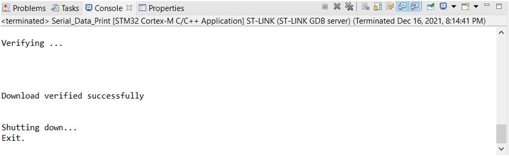
After a few moments, the code will be successfully sent to the STM32 board.
Otherwise, press the RESET button on your STM32
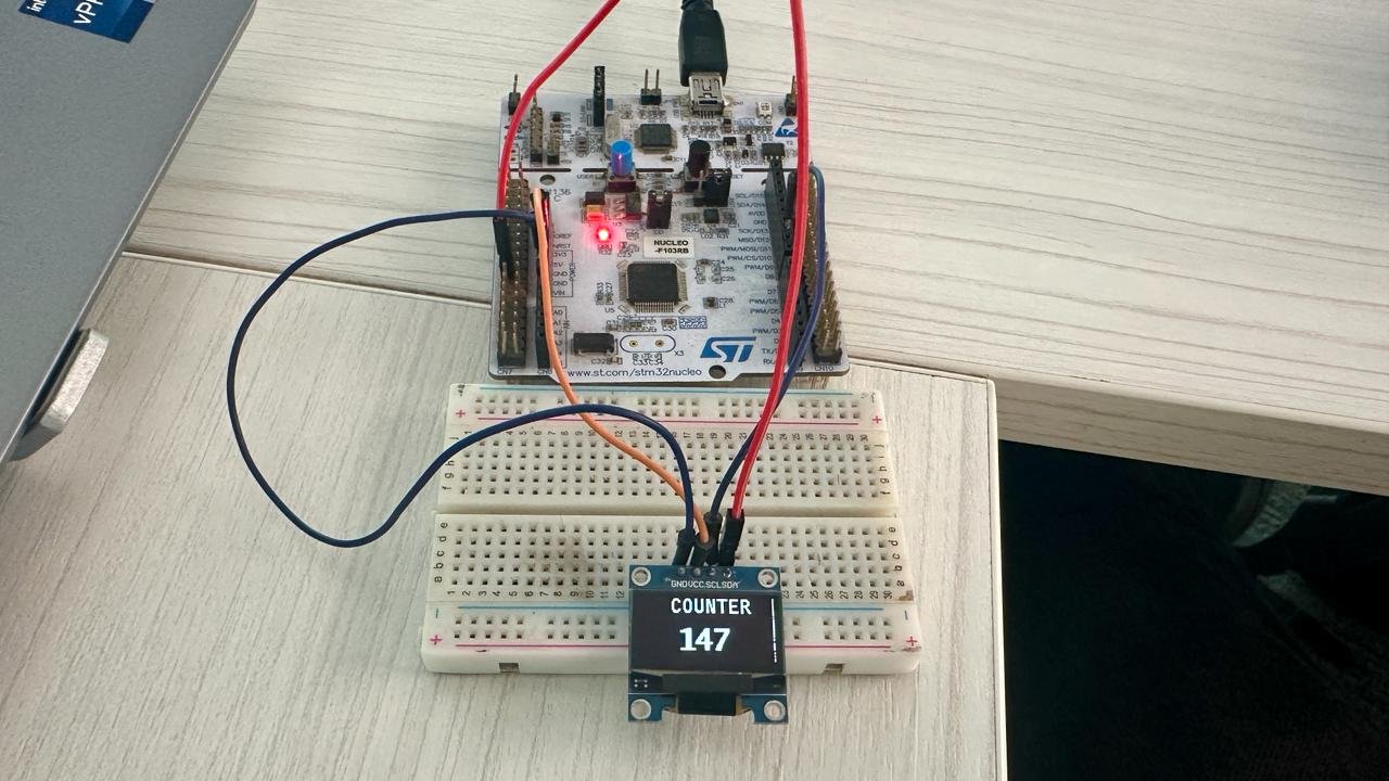
Once the code is uploaded to the board, the OLED starts displaying the different messages. Watch the video below to have a better insight.
Summary
In conclusion, this tutorial provides a guide on interfacing the SSD1306 OLED display with an STM32 Nucleo board using STM32CubeIDE and HAL libraries. It explains the advantages of OLED displays, including their excellent viewing angles, high pixel density, and cost-effectiveness. The tutorial begins with an overview of the 0.96-inch OLED display, including its pinout and how to connect it to the STM32 board. Finally, it details the programming steps in STM32CubeIDE to display various texts on the OLED screen.
Required components:
| Quantity | Component | Amazon.com |
|---|---|---|
| 1 | STM32 Nucleo Development Board with STM32F446RE MCU NUCLEO-F446RE | Buy here |
| 1 | Breadboard Jumper Wires Kit | Buy Here |
| 1 | OLED | Buy here |
You may also like to read:
- HC-05 Bluetooth Module with STM32 Nucleo using STM32CubeIDE
- STM32 Nucleo Timer in Counter Mode with STM32CubeIDE and HAL Libraries
- STM32 Nucleo Timer Encoder Mode with Rotary Encoder Example
- STM32 Nucleo Generate PWM with Timers using STM32CubeIDE
- STM32 Nucleo ADC with Polling, Interrupt and DMA STM32CubeIDE
Other OLED tutorials:
- ESP32 Real Time Clock (RTC) using DS1307 Module and display on OLED
- Interface DS1307 RTC Module with Arduino – Display Date/Time on OLED
- SSD1306 OLED with STM32 Blue Pill using STM32CubeIDE
- OLED Display with Raspberry Pi Pico using MicroPython
- IoT Based Analog and Digital Clock using OLED and ESP32/ESP8266