In this tutorial, we will discuss the digital to analog converter and its types. Usually, in real life, most of the data that we have is analog in nature. Why do we need converters? We need data converters to convert the analog or digital data available to us into some other form. There are two kinds of data converters: an analog to digital converter (ADC) and a digital to analog converter (DAC).
Introduction to Digital to Analog Converter
In electronics, a digital to analog converter system converts digital signals or data into analog signals or data. Whereas an analog to digital converter behaves oppositely to a digital to analog converter. These two conversion interfaces serve as the backbone for manipulating the data of digital electronic equipment. And then these devices need a processor in order to perform the required operation.
Hence, now let’s look at an example illustration of the DSP in the figure below. The ADC will convert the analog data from a microphone to a digital signal that a computer can process. After this, a DAC converts the digital sound signal from microphones back into an analog signal that speakers can transmit.


Digital to Analog Converter (DAC) Working
A digital to analog converter is a system that converts digital signals into analog signals. According to the Nyquist-Shannon sampling theory, sampled data can be reconstructed approximately perfectly with a proper bandwidth and the criteria given by Nyquist.
In DAC, it’s feasible to reconstruct a sampled amount of data into an analog signal with accurate and effective precision. After this, the amount of digital data can be produced by Application Specific Integrated Systems (ASICs), microprocessors, or a Field Programmable Gate Array (FPGA). This type of data requires an ultimate conversion to an analog signal or data to interact in the real world. In communication systems, digital data transmission is a faster and more convenient way to send data from one place to another. But in all this, the digital signals have to be converted into analog ones. Many digital to analog converters serve as sub-parts of the circuitry that is used in the analog to digital converters.
Types of Digital to Analog Converter
There are mainly two types of methods that are commonly used for digital to analog conversions. The Weighted Resistor method, the R-2R Ladder Network method, the serial digital to analog converter, the BCD digital to analog converter, and the bipolar digital to analog converter
DAC using Weighted Resistor Method
The weighted resistor method is shown in the following figure:
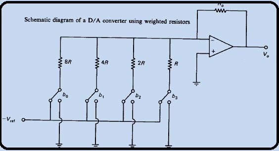
This type consists of the following four major components:
- N is the number of switches that represent a bit applied to the input provided.
- A ladder network supported by a weighted resistor. The resistor is inversely proportional to the corresponding binary digital signal.
- A reference voltage of V ref is provided.
- A Summing Amplifier
We can easily do the analysis of this circuit using the “Mill man’s Theorem” that states, “Voltage appearing at any node in a resistive network is equal to the summation of the current entering the node divided by the summation of the conductance connected to the node”.
Advantages/Disadvantages of Weighted Resistor Method
- The resistors present in the network have a wide variety of values that ensure stability and absolute accuracy across all the resistors.
- When the user gives a large value of n, the system considers the corresponding resistance to the LBS (Load Bearing System) as a large value. If it is compared with the provided input resistance of the amplifier, this all leads to accurate results.
R-2R Ladder Network DAC
The R-2R electrical device ladder network directly converts a parallel digital voltage into an analog voltage. Every digital input (b0, b1, etc.) adds its own weighted contribution to the analog output. Thus, this network has some distinctive and attention-grabbing properties. Easily climbable to any desired variety of bits. It uses only two values of resistors that work well for simple and correct fabrication and integration. Output resistance is adequate for R despite the number of bits, simplifying filtering and adding additional analog signal processing circuitry. Analyzing the R-2R network brings back memories of the ostensibly infinite kinds of networks that we’re asked to unravel throughout our undergrad engineering science studies.
Working of R-2R Ladder Network Digital to Analog Converter
The fact is that the analysis of this network and the way it works is kind of easy. By organizing the application of Thevenin equivalent circuits and superposition, we will simply show how the R-2R circuit works. Let’s start by analyzing the output resistance operating through the circuit and simplifying it with Thevenin equivalents, which makes this method easy. Thevenin says that if the circuit contains linear components like voltage sources, current sources, and resistors, we will just cut our circuit for any purpose and replace everything on one facet of the cut with a voltage supply and one series electrical device. The voltage supply is the open-circuit voltage at the cut point, and the series electrical device is the equivalent circuit resistance at the short of all voltage sources.
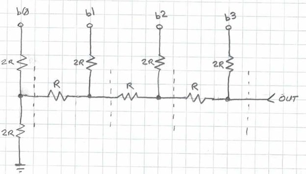
Cut Lines
A figure below shows the locations of the “cut lines” we’ll use to modify this circuit to calculate its output resistance. So, for this analysis, we consider all the digital inputs as short-to-ground. The two pairs of R resistors to the left of the primary cut line in the following figure seem to be in parallel (where the digital bit b0 connects to ground). The replacement might occur with one electrical device, R, as we can see in the figure below. The series combination of the 2 R electrical devices on the left of the following figure mixes to one valuable 2R resistor. This resistor is in parallel with the 2R electrical device to b1. We can notice that this method repeats itself anytime we have a tendency to work from left to right, substituting mixtures of resistors with their equivalents.

Circuit Simplification
As we will see in figure below, the circuit ultimately simplifies to one electrical device, R. Thus, the output resistance of the R-2R electrical device network is usually adequate for R, despite the dimensions (number of bits) of the network. This simplifies the planning of any filtering, amplification, or extra analog signal acquisition electronic equipment that will follow the network. Next, we’ll examine the way to calculate the analog voltage output for a given parallel digital input on the b0, b1, etc. inputs.

We’ll use a Thevenin equivalents technique, which is easier and faster than as superposition. Superposition tells us that if we separately calculate the contribution of a given supply to the output (with all other voltage sources shorted and current sources opened), we’ll then total the results for every of the sources to get the ultimate result for the output. We’ll calculate the contribution of two of the bits of our 4-bit R-2R DAC in figure below to point out the method. We’ll assume the bits b0 and b2 area unit logic are high and the bits b1 and b3 area unit logic are low (ground).
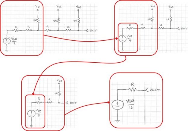
Calculating Output Voltage
From the Thevenin equivalent analysis shown earlier, we all know that we will replace any portion of this circuit to the left of any of the cut lines with an electrical device with valuable R, as we can see from the opening move in figure below. Next, we have a tendency to apply an equivalent Thevenin method to the output. As you will have already suspected, the contribution of bit b2 is solely Vb2/4. Thus, the analog output voltage bits b0 and b2 are adequate to logic one, which is solely due to Vb0/16 + Vb2/4. So, in a very general sense, the contribution of every bit to the output could be an easy binary coefficient operation for every bit. As we employ back from the savings bank to the LSB, the voltage contribution for every bit is cut by 0.5.

Advantages/Disadvantages of R-2R Ladder Network DAC
- We use only two resistor values R and 2R.
- R-2R ladder Networks are monolithic in nature.
- The actual value used by the R is less important if we compare it with the large values.
Conclusion
In conclusion, this provides an in-depth overview of the digital to analog converter, along with its introduction, working, types, advantages, and disadvantages. This tutorial helps us better understand the concept of DACs and how we can implement them in our projects. Hopefully, this was helpful in expanding your knowledge.
You may also like to read:
- ESP32-CAM Capture Photo and Save to MicroSD Card
- How to use DAC Module of Pic Microcontroller and Generate waveforms
- UART/USART Communication STM32F4 Discovery Board – HAL UART Driver
- 3-bit Flash Analog to Digital Converter with Example Circuit
- ESP32 ESP-NOW Two way Communication (Arduino IDE)
- ESP32 Send Sensor Readings to ThingSpeak using Arduino IDE (BME280)
- STM32 Nucleo GPIO Pins with LED Blinking using STM32CubeIDE
- Get Epoch/Unix time with ESP32 through NTP server using Arduino IDE
- Raspberry Pi Pico W MicroPython Publish Sensor Readings to Google Sheets
- Raspberry Pi Pico W MQTT Client Publish Subscribe Messages
This concludes today’s article. If you face any issues or difficulties, let us know in the comment section below.
thanks for giving the note