ESP8266 development board and its introduction and how to program it with Arduino IDE. I have already posted many articles and projects on esp8266. In these projects and articles, I ussed ESP8266 wifi module maximum time with other microcontrollersl like interfacing esp8266 with pic microcontroller, how to interface esp8266 with Arduino and many others. But in today’s tutorial, we will see how we can use ESP8266 development board as a stand along board to make embedded systems based projects and applications. It also has built in processor on it. Earlier we were communicating with this processor through AT commands. But Now we will see how we can program esp8266 wifi module through Arduino IDE. Programming this development board with Arduino IDE is as easy as programming Arduino with the help of Arduino IDE.
Types of ESP8266 development boards
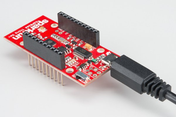
There are many ESP8266 development boards available in market. But maximum ESP8266 development board do not have on board FTDI USB-to-Serial chip on it. Having on board FTDI USB-to-Serial chip makes your life easier while programming this module. Otherwise you have to connect FTDI USB-to-Serial module external with esp8266 wifi module which makes your project more costly and increase hassle of dealing with more wires. There are many companis which are developing these wifi based development boards. But in this article, I am going to use a ESP8266 Thing Development Board Hookup Guide by sparkfun. It has a on chip FTDI USD to serial converter which can be used to program the board through Arduino IDE serially. So we do not need any external programmer to program this board. It has pin headers to connect with external components like LED blinking, relay control etc. I will discuss all these examples in later tutorials. Pins are divideded in two parallel rows and they are compatiable with bread board means you can connect this board directly into bread board. 
Hardware pins discription of ESP8266 development board
Details of all pins on the left hand side of module are give below.

Details of pins on the right hand side of the module are given below:
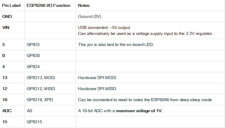
This module has general purpose Input output pins, one analog to digital converter. But if you need more than one ADC, you can use ADC expander IC with this module. It also has features of I2C communication and SPI communication which is very useful for communicating with various sensors and digital displays like GLCD’s and TFT displays. This board has on board LED which is connected with pin number 5 of esp8266
How to program esp8266 development board with Arduino IDE
Now lets see how we can program esp8266 development board using Arduino IDE. Follow these steps:
- First of all you need to power this board with 5 volt power supply. you can power it through separate power supply or through micro USB cable by connecting it through computer as shown in picture below.
- You will use same usb cable to program this board through Arduino IDE.
- After that connect your USB cable to laptop or computer
- you need to install FTDI drivers on your computer if you do not have already installed on your computer. you can download FTDI drivers from this link
- . After installing FTDI drivers, Click on Arduino IDE icon and open it. I assumed that you have already installed Arduino IDE software on your system.
- After opening Arduino IDE, click on file menu and open preferences and paste the following URL to Additional board manager URLs
http://arduino.esp8266.com/stable/package_esp8266com_index.json
- Now go to tools > Boards > Board Manager and types esp8266 in search window and click on install button. It will install all libraries and defintions of esp8266 in Arduino IDE. If you have already done these steps earlier, you do not need to do last two steps again.
- Now go to tools> Boards and select esp8266 generic board.
- After that go to device manager of your computer and check to which COM pin of your system FTDI is connected.
- Now select same port from tools>Ports
- Now you are ready to program your esp8266 development board with Arduino IDE.
LED blinking code using esp8266
Lets write a simple LED blinking code and check if is it works on our esp8266 development board or not. Paste the following code in Arduino and click on compile. It will successfully compile your code.
#define ESP8266_LED 5

void setup()
{
 pinMode(ESP8266_LED, OUTPUT);
}

void loop()
{
 digitalWrite(ESP8266_LED, HIGH); // LED off
 delay(500);
 digitalWrite(ESP8266_LED, LOW); // LED on
 delay(500);
}
Video lecture on led blinking with esp8266 development board
In above code, we are using pin number 5 of esp8266 as a output and ESP8266 Thing Development Board has on board LED connected with pin number five. This code will blink the Led after every five hundred mili second.