In the world of solar energy, a vital component in the charging process of batteries is the solar charge controller. This electronic device acts as a bridge between the solar panels and the battery, regulating the flow of charges and protecting against under and overvoltages. While many solar charge controllers utilize microcontrollers for efficient charging, there is a growing interest in simpler designs without the need for sophisticated programming. In this article, we will explore the fascinating world of a 15 Ampere solar charge controller that operates without a microcontroller. We will delve into the fundamental concepts, design considerations, selection process, and even provide a detailed circuit diagram for this elegant and straightforward solution. So, let’s embark on this enlightening journey and discover the wonders of a microcontroller-free solar charge controller.
15 Ampere solar charge controller without a microcontroller. In this article, you will learn the following things:
- What is a solar charge controller?
- How to design a solar charge controller?
- How to select a solar charge controller?
- Circuit diagram of 15A solar charge controller?
- Working of the solar charge controller.
What is a Solar Charge Controller?
Solar charge controller is an electronic device connected between the battery and solar panels. It is used to regulate the flow of charges from the solar panels to the battery. In other words, a solar charge controller is used to control the flow of charges from solar panels to the battery. It provides protection against an overflow of charges from the solar panels to the battery and is also used to protect batteries from under voltages. In essence, solar charge controllers provide protection against under and overvoltages of batteries during the charging and discharging process.
How to design a solar charge controller?
Many methods have been developed for solar charge controllers. There are various types of solar charge controllers available in the market, but mainly three types are commonly used.
- Simple solar charge controller: This type of solar charge controller uses analog electronics to control the flow of charges.
- PWM-based solar charge controllers: This type of solar charge controller uses microcontrollers to charge batteries through pulse width modulation methods.
- MPPT solar charge controllers: MPPT stands for maximum power point tracking. This type of charge controller uses MPPT techniques to charge batteries from solar panels.
I have noticed that many people are searching on various websites about solar charge controllers, but they are not aware of the use of microcontrollers. It is important to note that high-rated solar charge controllers make use of microcontrollers. Therefore, I have decided to publish an article on a solar charge controller that does not require a microcontroller. In this article, I will be sharing the circuit diagram of a 15 Ampere solar charge controller that does not utilize any microcontroller. This circuit diagram is very straightforward and simple to understand.
How to Select a Solar Charge Controller?
Before making or purchasing any charge controller for your solar panels, a question may arise: what should be the rating of your charge controller? Let me provide you with an example to help answer this question. For instance, if you have 200-watt solar panels with an open-circuit voltage of 24 volts and a closed-circuit voltage of around 18 volts, you can calculate the rating of the required charge controller for your solar panel using a simple power formula. The power formula for DC power can be used to determine this.
P = V * I;we know the values of power and voltage which is P = 200W and V = 18 V. By putting the above values in the power formula:
I = 200 / 18 = 11.11 AmpereSo, the calculated value of the current is 11.11A. Let’s suppose the voltage of the solar panels may decrease to a lower value, such as 15 volts. In that case, the current will increase. Therefore, it is recommended to select a charge controller that has a slightly higher value than the calculated one. I hope this clarifies your question on how to select a solar charge controller.
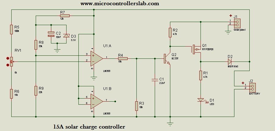
Circuit Diagram of 15A Solar Charge Controller
Circuit diagram of a 15A solar charge controller is shown below. If you want to use this circuit for a higher rating, you can use more than one solar charge controller in series to increase the current rating of the charge controller. The circuit diagram shown below is the simplest circuit diagram of a charge controller because it does not have any microcontroller. This circuit of the charge controller uses analog electronics instead of digital electronics.
Components list
Category,Reference,Value,Order Code
Resistors,"R1",4.7k,
Resistors,"R2",4.7k,
Resistors,"R3",10k,
Resistors,"R4",18k,
Resistors,"R5",100k,
Resistors,"R6",15k,
Resistors,"R7",12k,
Resistors,"R8",33k,
Resistors,"R9",22k,
Capacitors,"C1",2.2nF,
Capacitors,"C2",10uF,
Integrated Circuits,"U1",LM358,
Transistors,"Q1",RFP30P05,
Transistors,"Q2",BC337,
Diodes,"D1",LED,
Diodes,"D2",MBR1645,
Diodes,"D3",5.1V,
Miscellaneous,"J1",Solar panel,
Miscellaneous,"J2",BATTERY,
Miscellaneous,"RV1",5k,
Working of Solar Charge Controller
15-ampere charge controller circuit diagram uses analog electronic components to control the flow of charges from the solar panel to the battery. The RFP30P05 P-channel MOSFET is used to charge the battery. The RFP30P05 MOSFET has an approximate rating of 20A, meaning it can easily pass a current of up to 20 amperes. For more information, please refer to the datasheet of the RFP30P05.
The LM358 operational amplifier is utilized to turn the P-channel MOSFET on or off when the battery is charged up to 13.6 volts. When the battery reaches 13.6 volts, the LM358 turns off the MOSFET by providing a low signal to resistor R4. The LM358 is used as a comparator, comparing the battery voltage through voltage dividers connected to the inverting and non-inverting pins of the LM358 operational amplifier. Connect the solar panel to connector J1 and the battery terminals to connector J2. The LED D1 indicates the status of the charging process.
Thank you for reading the article on the solar charge controller. Kindly consider sharing this article with your friends as well. If you would like to receive updates of all my posts in your inbox, please subscribe to my blog. Happy learning!
In my project, i need 5A charge controller. Kindly tell me the specifications according to 5A. Thanks.
please design a circuit diagram for 15 amp 24 volt solar charge controller.thank you.
can i connect with 255w solar pennel ?????
I also want a chager for 24V
i would like to inquire for the alternatives to mosfet RFP30P05
how can i adjust the voltage output from 13.6v to 14.2 volts?
lm358 4th pin has to be ground???
yes
excuse me can i ask what component can replace RFP3050P?
What about the LM358(U1:B) 7th pin we have to connect it anywhere or leave it as it is??plus can i use this circuit for the following specification
150watt solar panell and 30AH or 40AH battery???
30 or 40ah battery means you can use 3 to 7 amperes current for charging battery. 150 WATT will give you more current than that so i would suggest you to use less power solar panel.Make sure voltage for solar panel should be 17 as said in post.
Can i connect 12V solar panel in this circuit? i think there is nothing to do with voltage in this circuit , Only current from panel is charging battery.
thanks sir. this was very helpful, it works the way i wanted, vireing the out put was very easy for me using the RV1 5kohms.but to get the P-channel mosfet transistor was was a problem in my area. so, i used IRF3205 N-channel mosfet transistor and control the solar voltage negetively because the transistor i used was N-channel. thanks alot sir. this circuit made my day.
U got perfect results on pcb ? Have You charged battery with this circuit and please tell me the power of solar panel you have used?
but lm358 4th pin connected battery positive and 8th pin connected ground in the circuit.
What part was used for RV1 and could you please provide a link to the part at Digikey or another source? Thanks!
Best,
Chris
RV1 is a potentiometer. It works like a resistor but controls two sides of output.
I want 48V controller
What about U1B 7 the pin
I want to 24v charger circuit .
Is it a pwm or simply sensing voltage. Plz reply
Can the same circuit be modified for 12V 10A solar charge controller??? If yes, what are the required modifications??
Hie how do i adjust rv1?
im getting output same as input what might be the problem.
and we used substitute for RF30305 and MBR1645
i have a 22.5 volt and 7 amp solar cells and MPPT 30 amp, i want to design a circuit for my system ? what modification should i do to use your 15 amp circuit ?
Please suggest to solar charge controller.
I used in 250w solar panel,
Above circuit is ok or any changes
Mmmmm nice and simple, Im just not sure about changes to accomodate my 100V panel (A Mitsubishi MT100) which can have open circuit voltage of 150V in bright sunlight. If I assume 12V battery banks for a smaller application, …. suggestions?
The connection of your LM358 is so confusing. Pin 8 on the ground and just how many pin 1 does this IC have?
WHAT IS THE VOLTAGE RATING FOR THE 15AMP SOLAR CHARGE CONTROLLER? I AM ASKING THIS BECAUSE YOU SIMPLY MENTIONED THE CURRENT RATING AND NOT THE VOLTAGE RATING.
THE OTHER ONE IMPORTANT THING I FORGOT TO ASK IS THE MINIMUM SIZE AND MAXIMUM SIZE OF SOLAR PANEL TO USE IN TERMS OF WATTAGE.
How can I modify the simple solar charge controller to obtain a 1A charge controller for my mini hydro DC generation project
Hello,
I have a solar panel for 48 volt system, so I would like to have this controller set for that application.
Would you please give me an idea on the components values, I will have to add a volt regulation of 12 volt for the opamp, not a problem, but there is the led light that will require a proper voltage…
Thanks for your assistance.
Regards