In this tutorial, we will learn to use I2C communication modules of TM4C123G microcontrollers. The TM4C123GH6PM microcontroller which is integrated on the Tiva Launchpad board has four I2C channels inside the chip such as 12C0, 12C1, 12C2, and I2C3. Firstly, We will use a bare-metal embedded approach to configure I2C modules using peripheral registers. Keil uvision IDE will be used to write program for I2C master and slave configuration.
Pre-requisities:
- How to Download and Install Keil uVision for ARM and 8051
- Getting started with Keil uVision: Write your first Program for Tiva LaunchPad
Recommended Components
The following components are used in this project or are helpful for getting started with TM4C123 Tiva C LaunchPad development.
| Component | How it’s used in this project | Buy on Amazon |
|---|---|---|
| TM4C123G Tiva C LaunchPad | The I2C master board sending commands | Check Price |
| Micro USB Cable | Programs and powers the board via onboard ICDI | Check Price |
| Arduino Uno | The I2C slave device receiving commands over the bus | Check Price |
| Breadboard | Connects the I2C bus between the two boards | Check Price |
| Jumper Wires | Wire the SDA and SCL lines between the boards | Check Price |
As an Amazon Associate we earn from qualifying purchases. Prices and availability are accurate as of the date/time indicated and are subject to change.
I2C Communication Introduction
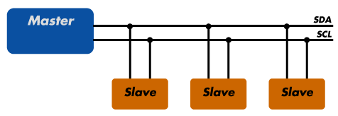
I2C is also known as an inter-integrated circuit or IIC or I square C. It is a synchronous half-duplex serial communication protocol. I²C (Inter-Integrated Circuit) is a synchronous, multi-master, multi-slave communication protocol that uses two bidirectional lines: SDA (data) and SCL (clock). It allows devices to communicate by sending data in a master-slave configuration, where the master controls the clock and initiates communication. Each device on the bus has a unique address, enabling multiple devices to share the same bus lines.
Furthermore, it is a multi-master bus protocol that requires only two wires to transfer data serially that are SCL and SDA.
- SDA ( Bidirectional data line)
- SCL ( Bidirectional clock line)
I2C Bus Connection
Each device connected with the I2C bus can be either in master mode or in slave mode. But only a master device can initiate the data transfer process. Usually, there are one master and one slave or multiple slave devices connects with the same I2C bus through pull-up resistors. Each salve address has a 7-bit unique address.
For example, if we configure the TM4C123G Tiva launchpad as a master device and we can connect multiple slave devices with the same bus.
For more information on I2C Communication, you can read this post:
TM4C123G I2C Communication Modules
As we mentioned earlier, TM4C123 microcontrollers have four I2C modules inside the chip. Moreover, each module can be configured either as a master, slave, or both master and slave at a time.
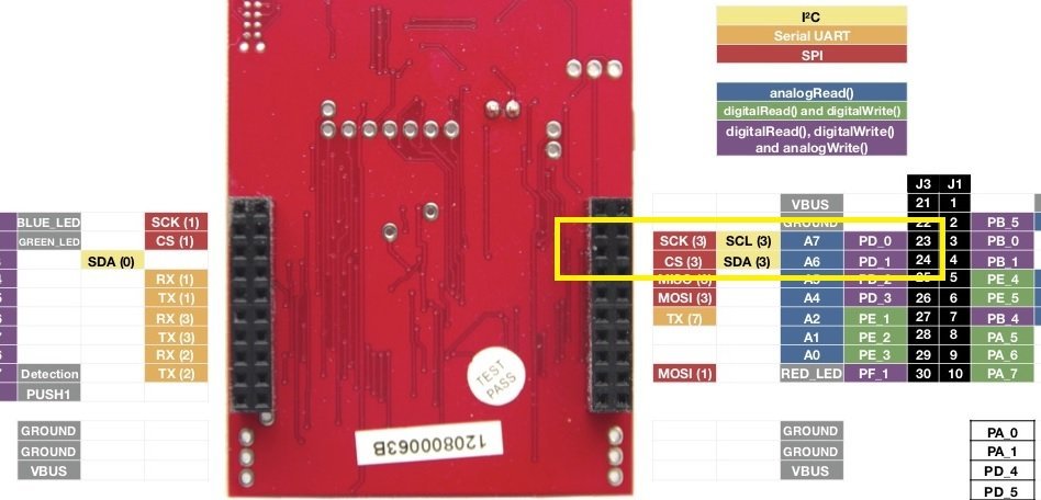
I2C Pins TM4C123 Tiva
This table shows the clock line and data line pins of each I2C module on TM4C123 pinout.
| I2C Module | SCL Pin | SDA Pin |
|---|---|---|
| I2C0 | PB2 | PB3 |
| I2C1 | PA6 | PA7 |
| I2C2 | PE4 | PE5 |
| I2C3 | PD0 | PD1 |
As you know that each GPIO pin of microcontroller has multiple functions or these pins are shared with different peripherals using multiplexing techniques. But each pin can be used for one peripheral or for one function at a given time. A peripheral select register is used to enable or disable the alternate function of every pin.
All these I2C modules supports four data transmission speeds.
- Standard (100 Kbps)
- Fast-mode (400 Kbps)
- Fast-mode plus (1 Mbps)
- High-speed mode (3.33 Mbps)
Steps configure TM4C123 I2C module as a Master
As we mentioned earlier, each I2C module can be configured either as a master or a slave. In this tutorial, we will see steps to configure the I2C3 module as a master. But you can follow the same steps to configure any I2C module in both master and slave configurations.
Enable Clock
- Enable clock to I2C3 module and GPIO pins which are used as SDA and SCL pins using RCGC12C3 and RCGCGPIO registers.
- Also, disable the ADC alternate functions of RD0 and RD1 pins using the GPIOAFSEL register and select the I2C3 alternate function using the GPIOPCTL register.
- Select Open drain operation for the I2CSDA pin that is the RD1 pin.
- Enable Master mode by setting appropriate bits of I2C3->MCR register.
Select Clock Speed
For example, we want to use speed of 100kbps. Select clock speed of 100kbps by using this formula:
(1 + TIME_PERIOD ) = SYS_CLK /(2*( SCL_LP + SCL_HP ) * I2C_CLK_Freq )
TIME_PERIOD = 16 ,000 ,000/(2(6+4) *100000) – 1 = 7
Load this time period value to I2C3->MTPR register.
Master Transmit Data
- Specify the slave address of the master and that the next operation is a Transmit by writing the
- I2CMSA register with a value of 0x0000.0076. This sets the slave address to 0x3B.
- Place data (byte) to be transmitted in the data register by writing the I2CMDR register with the
desired data. - Initiate a single byte transmit of the data from Master to Slave by writing the I2CMCS register with a value of 0x0000.0007 (STOP, START, RUN).
- Wait until the transmission completes by polling the I2CMCS register’s BUSBSY bit until it has been cleared.
- Check the ERROR bit in the I2CMCS register to confirm the transmit was acknowledged
You can follow the same steps to configure master to receive data from the slave.
TM4C123 I2C Code
In this code, we initialized the I2C3 module of TM4C123 microcontroller as a master. This example code can be used to transmit and receive multiple bytes. As you can see in this picture, RD0 and RD1 are data line and clock line pins of I2C3 module.
#include "TM4C123GH6PM.h"

// Function prototypes initialize, tranmit and rea functions
void I2C3_Init ( void );
char I2C3_Write_Multiple(int slave_address, char slave_memory_address, int bytes_count, char* data);
char I2C3_read_Multiple(int slave_address, char slave_memory_address, int bytes_count, char* data);

int main(void)
{
	 I2C3_Init();

}
// I2C intialization and GPIO alternate function configuration
void I2C3_Init ( void )
{
SYSCTL->RCGCGPIO  |= 0x00000008 ; // Enable the clock for port D
SYSCTL->RCGCI2C   |= 0x00000008 ; // Enable the clock for I2C 3
GPIOD->DEN |= 0x03; // Assert DEN for port D
// Configure Port D pins 0 and 1 as I2C 3
GPIOD->AFSEL |= 0x00000003 ;
GPIOD->PCTL |= 0x00000033 ;
GPIOD->ODR |= 0x00000002 ; // SDA (PD1 ) pin as open darin
I2C3->MCR  = 0x0010 ; // Enable I2C 3 master function
/* Configure I2C 3 clock frequency
(1 + TIME_PERIOD ) = SYS_CLK /(2*
( SCL_LP + SCL_HP ) * I2C_CLK_Freq )
TIME_PERIOD = 16 ,000 ,000/(2(6+4) *100000) - 1 = 7 */
I2C3->MTPR  = 0x07 ;
}
/* wait untill I2C Master module is busy */
/*  and if not busy and no error return 0 */
static int I2C_wait_till_done(void)
{
    while(I2C3->MCS & 1);   /* wait until I2C master is not busy */
    return I2C3->MCS & 0xE; /* return I2C error code, 0 if no error*/
}
// Receive one byte of data from I2C slave device
char I2C3_Write_Multiple(int slave_address, char slave_memory_address, int bytes_count, char* data)
{
    char error;
    if (bytes_count <= 0)
        return -1;                  /* no write was performed */
    /* send slave address and starting address */
    I2C3->MSA = slave_address << 1;
    I2C3->MDR = slave_memory_address;
    I2C3->MCS = 3;                  /* S-(saddr+w)-ACK-maddr-ACK */

    error = I2C_wait_till_done();   /* wait until write is complete */
    if (error) return error;

    /* send data one byte at a time */
    while (bytes_count > 1)
    {
        I2C3->MDR = *data++;             /* write the next byte */
        I2C3->MCS = 1;                   /* -data-ACK- */
        error = I2C_wait_till_done();
        if (error) return error;
        bytes_count--;
    }

    /* send last byte and a STOP */
    I2C3->MDR = *data++;                 /* write the last byte */
    I2C3->MCS = 5;                       /* -data-ACK-P */
    error = I2C_wait_till_done();
    while(I2C3->MCS & 0x40);             /* wait until bus is not busy */
    if (error) return error;
    return 0;       /* no error */
}
/* This function reds from slave memory location of slave address */
/* read address should be specified in the second argument */
/* read: S-(saddr+w)-ACK-maddr-ACK-R-(saddr+r)-ACK-data-ACK-data-ACK-...-data-NACK-P */
char I2C3_read_Multiple(int slave_address, char slave_memory_address, int bytes_count, char* data)
{
    char error;

    if (bytes_count <= 0)
        return -1;         /* no read was performed */

    /* send slave address and starting address */
    I2C1->MSA = slave_address << 1;
    I2C1->MDR = slave_memory_address;
    I2C1->MCS = 3;       /* S-(saddr+w)-ACK-maddr-ACK */
    error = I2C_wait_till_done();
    if (error)
        return error;

    /* to change bus from write to read, send restart with slave addr */
    I2C1->MSA = (slave_address << 1) + 1;   /* restart: -R-(saddr+r)-ACK */

    if (bytes_count == 1)             /* if last byte, don't ack */
        I2C1->MCS = 7;              /* -data-NACK-P */
    else                            /* else ack */
        I2C1->MCS = 0xB;            /* -data-ACK- */
    error = I2C_wait_till_done();
    if (error) return error;

    *data++ = I2C1->MDR;            /* store the data received */

    if (--bytes_count == 0)           /* if single byte read, done */
    {
        while(I2C1->MCS & 0x40);    /* wait until bus is not busy */
        return 0;       /* no error */
    }

    /* read the rest of the bytes */
    while (bytes_count > 1)
    {
        I2C1->MCS = 9;              /* -data-ACK- */
        error = I2C_wait_till_done();
        if (error) return error;
        bytes_count--;
        *data++ = I2C1->MDR;        /* store data received */
    }

    I2C1->MCS = 5;                  /* -data-NACK-P */
    error = I2C_wait_till_done();
    *data = I2C1->MDR;              /* store data received */
    while(I2C1->MCS & 0x40);        /* wait until bus is not busy */

    return 0;       /* no error */
}
I2C Communication between Arduino and TM4C123 Launchpad
In order to test above code, we will peform I2C communication between Arduino and Tm4c123 Tiva launchpad. Arduino will be configured as a slave and TM4C123G microcontroller as a master. We will send an instruction from tiva launchpad to Arduino over I2C bus. The instruction will either turn on or turn off on board LED of Arduino board.
Make connection between Tiva C and Arduino according to this circuit diagram:
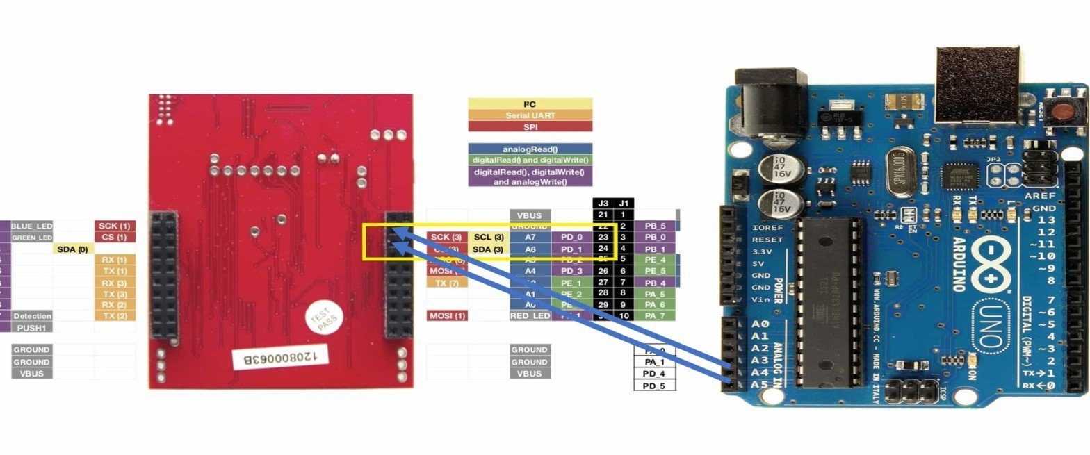
Upload this code to your Arduino Board. This Arduino code uses the I2C module of Arduino as a slave and the address assign to this slave device is 4. If a character received by this device is 0x00, it will turn on the onboard LED of Arduino and if a character received by this device is 0x01, it will turn off the onboard LED.
Pin A5 is clock, or SCL, pin) and pin 4 is a data, or SDA pin of Arduino Uno.
#include <Wire.h>
const int ledPin =  LED_BUILTIN;// the number of the LED pin
void setup()
{
  Wire.begin(4);                // join i2c bus with address #4
  Wire.onReceive(receiveEvent); // register event
  Serial.begin(9600);           // start serial for output
  pinMode(ledPin, OUTPUT);
}

void loop()
{
  delay(100);
}

// function that executes whenever data is received from master
// this function is registered as an event, see setup()
void receiveEvent(int howMany)
{
  while(1 < Wire.available()) // loop through all but the last
  {
    char c = Wire.read(); // receive byte as a character
    Serial.print(c);         // print the character
     if ( c == 2 )
      digitalWrite(ledPin, HIGH);
      else if(c == 1)
       digitalWrite(ledPin, LOW);
  }
  int x = Wire.read();    // receive byte as an integer
  Serial.println(x);         // print the integer
   if ( x == 2 )
      digitalWrite(ledPin, HIGH);
      else if(x == 1)
       digitalWrite(ledPin, LOW);
}
Upload this code to TM4C123G Tiva C Launchpad. This example code uses an onboard push button to transmit data to Arduino. If the push button is pressed, TM4C123 Tiva launchpad, transmit 0x00 and if not pressed, it transfers 0x01 via the I2C3 module.
#include "TM4C123GH6PM.h"

// Function prototypes initialize, tranmit and rea functions
void I2C3_Init ( void );
char I2C3_Write_Multiple(int slave_address, char slave_memory_address, int bytes_count, char* data);
char I2C3_read_Multiple(int slave_address, char slave_memory_address, int bytes_count, char* data);

int main(void)
{
	 char data[2] = {0x01,0x02};
	 I2C3_Init();
	 SYSCTL->RCGCGPIO |= 0x20;   /* enable clock to GPIOF */
   GPIOF->LOCK = 0x4C4F434B;   // unlockGPIOCR register
   GPIOF->PUR |= 0x10;        // Enable Pull Up resistor PF4
   GPIOF->DIR |= 0x08;          //set PF1 as an output and PF4 as an input pin
   GPIOF->DEN |= 0x18;         // Enable PF1 and PF4 as a digital GPIO pins

	while (1)
	{
    unsigned int	value = GPIOF->DATA;
		value = value >> 1;
		GPIOF->DATA = value;
		if(value & (5<<1))
    I2C3_Write_Multiple(4, 0, 1, &data[1]);
		else
		I2C3_Write_Multiple(4, 0, 1, &data[0]);

	}

}
// I2C intialization and GPIO alternate function configuration
void I2C3_Init ( void )
{
SYSCTL->RCGCGPIO  |= 0x00000008 ; // Enable the clock for port D
SYSCTL->RCGCI2C   |= 0x00000008 ; // Enable the clock for I2C 3
GPIOD->DEN |= 0x03; // Assert DEN for port D
// Configure Port D pins 0 and 1 as I2C 3
GPIOD->AFSEL |= 0x00000003 ;
GPIOD->PCTL |= 0x00000033 ;
GPIOD->ODR |= 0x00000002 ; // SDA (PD1 ) pin as open darin
I2C3->MCR  = 0x0010 ; // Enable I2C 3 master function
/* Configure I2C 3 clock frequency
(1 + TIME_PERIOD ) = SYS_CLK /(2*
( SCL_LP + SCL_HP ) * I2C_CLK_Freq )
TIME_PERIOD = 16 ,000 ,000/(2(6+4) *100000) - 1 = 7 */
I2C3->MTPR  = 0x07 ;
}
/* wait untill I2C Master module is busy */
/*  and if not busy and no error return 0 */
static int I2C_wait_till_done(void)
{
    while(I2C3->MCS & 1);   /* wait until I2C master is not busy */
    return I2C3->MCS & 0xE; /* return I2C error code, 0 if no error*/
}
// Receive one byte of data from I2C slave device
char I2C3_Write_Multiple(int slave_address, char slave_memory_address, int bytes_count, char* data)
{
    char error;
    if (bytes_count <= 0)
        return -1;                  /* no write was performed */
    /* send slave address and starting address */
    I2C3->MSA = slave_address << 1;
    I2C3->MDR = slave_memory_address;
    I2C3->MCS = 3;                  /* S-(saddr+w)-ACK-maddr-ACK */

    error = I2C_wait_till_done();   /* wait until write is complete */
    if (error) return error;

    /* send data one byte at a time */
    while (bytes_count > 1)
    {
        I2C3->MDR = *data++;             /* write the next byte */
        I2C3->MCS = 1;                   /* -data-ACK- */
        error = I2C_wait_till_done();
        if (error) return error;
        bytes_count--;
    }

    /* send last byte and a STOP */
    I2C3->MDR = *data++;                 /* write the last byte */
    I2C3->MCS = 5;                       /* -data-ACK-P */
    error = I2C_wait_till_done();
    while(I2C3->MCS & 0x40);             /* wait until bus is not busy */
    if (error) return error;
    return 0;       /* no error */
}
Video Demo
Conclusion
In conclusion, this tutorial provided a comprehensive guide to configuring and using the I2C communication modules of the TM4C123G microcontroller on the Tiva Launchpad. By following a bare-metal approach, we explored the essential steps to initialize and operate I2C as both master and slave using Keil uVision IDE. Additionally, a practical example demonstrated I2C communication between the Tiva Launchpad and an Arduino, showcasing how the TM4C123G can be effectively utilized in multi-device setups. With this knowledge, you can confidently implement I2C communication in your embedded projects using the TM4C123G microcontroller.
If you want to interface any I2C based sensor with TM4C123, you can see this example of interfacing MPU6050:
Related Articles:
Do we need pull-up resisters? Is this the latest version of the code? I tried the code and the arduino did not respond to the command sent by tiva c. Arduino worked as a slave with another arduino device.
Yes, this code works fine. Please check the video demo. Pull-up resistors are not required.
I may have had a (h/w) port issue. Changed ports and it works. thanks for the quick reply. The Tiva C tutorials are awesome!
Can we not try out this example on simulation environment (Proteus)
I’d love to see a demo on an HD44780 LCD. Cheaper, more practical and most of us doing uC work probably have the LCD available.
how to use TM4C123 I2C module as a slave?? , in this you only used as master.