In this user guide, we will focus on TMP36 temperature sensor and its interfacing with Arduino UNO. This sensor provides a highly precise temperature in centigrade. Most importantly, it produces output in dc voltage that we can measure easily with the help of any bare metal microcontrollers such as Arduino Uno, STM32F4, PIC16F877A. In the starting sections, we will see the sensor’s introduction, pinout, working principle, and how to use it with our Arduino board. Secondly, we will see an example to show temperature readings obtained from the sensor on the Serial Monitor in both degree Celsius and Fahrenheit. In the second example, we will display the temperature readings obtained from the sensor on a 16×2 LCD.
Recommended Components
The following components are used in this project or are helpful for building it with the Arduino.
| Component | How it’s used in this project | Buy on Amazon |
|---|---|---|
| Arduino Uno R3 | The main microcontroller board that runs the sketch and reads the sensors/modules in this project. | Check Price |
| Breadboard | Lets you wire the components to the Arduino without soldering for quick prototyping. | Check Price |
| Jumper Wires | Connect the Arduino pins to the module and other parts on the breadboard. | Check Price |
| 16×2 LCD (parallel) | Displays the TMP36 temperature readings in the LCD example. | Check Price |
| Resistor Kit (220Ω/4.7kΩ) | Provides the 220Ω resistor for the LCD backlight. | Check Price |
As an Amazon Associate we earn from qualifying purchases. Prices and availability are accurate as of the date/time indicated and are subject to change.
TMP36 Temperature Sensor Introduction
TMP36 is a low voltage temperature sensor chip which generates an analog voltage at the output which is linearly proportional to the Celsius temperature. Then convert this voltage into temperature based on a 10 mV/°C scale factor. It has a shutdown capability which limits the output current to less than 0.5 µA. It provides a supply current of up to 50 µA. This sensor provides a highly precise temperature in centigrade. On top of that, the Celsius temperature and an output voltage change linearly which makes it easy to compensate temperature/Voltage variations. Having a linear relationship is helpful. Because we will not require any external calibration circuit. Furthermore, it offers a very low output impedance. In short, it is very easy to interface this sensor with ADCs or microcontrollers having built-in ADCs.
Specifications
The table below shows some key specifications of the TMP36 sensor.
| Power supply | 2.7 V-5.5 V |
| Current consumption | 50µA |
| Temperature range | -40°C to 125°C |
| Accuracy | ±2°C |
| Output voltage at 25°C | 750 mV |
| Output voltage range | 100-2000 mV |
| Scale Factor | 10mV/°C for −40°C ≤ TA ≤ +125°C |
Features
- This device operates using a single supply.
- It operates within a range of +2.7 V to +5.5 V.
- This chip is calibrated in Celsius therefore external calibration is not required. It provides an output with ±2°C accuracy over the full temperature range.
- The operating range for temperature is -40 °C to +125 °C. However, it can operate up to +150 °C temperature but accuracy reduces.
- TMP36 has an output scale factor of 10 mV/°C.
- Quiescent current is less than 50 µA.
- The device works well when the supply current is below 50 μA, which offers very low self-heating.
- It has an automatic shutdown capability.
Applications
TMP36 IC is used mainly in thermostats and temperature measuring applications. It has low output impedance and produces a linear output. It does not require external calibration and therefore you don’t need external components. These devices can handle temperature ranges of -40°C to 150°C. All these features make this chip suitable for use in a variety of temperature measuring applications. These devices provide stable operation along with capacitive loads and drive 10,000 pF load without creating any oscillations.
These less expensive sensors can generate interrupts in microprocessor applications. The TMP36 chip measures the average temperature in industrial and environmental control applications. Fire Alarms detect the rise in temperature through this device and start operating when the temperature reaches a certain threshold limit. Different applications implement thermal protection mechanisms using this chip. It monitors CPU and other power systems provide thermal management by measuring temperature through TMP36.
TMP36 Pinout
TMP36 is a three-terminal temperature sensor.
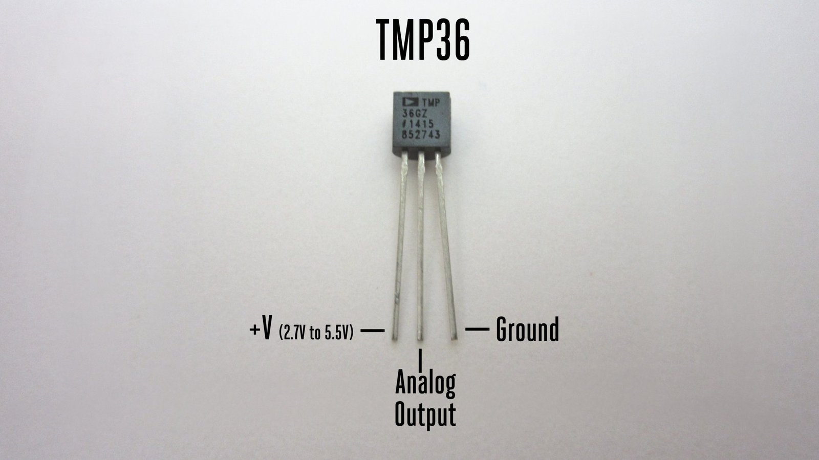
The table below shows its pins with a brief description.
| Pin | Description |
| Pin1 (+V) | This is the pin for supplying power to the sensor. Connect a positive power supply at this pin. |
| Pin2 (Vout) | This is the output that provides an analog voltage. This analog voltage is linearly proportional to temperature (in Celsius). |
| Pin3 (GND) | This is the ground pin. |
Interfacing TMP36 with Arduino
In this section, we will show you how to connect the TMP36 sensor with Arduino to be able to get the readings from the sensor. The connection is very simple.
Required Components:
- Arduino UNO board
- TMP36 temperature sensor
- Breadboard
- Connecting Wires
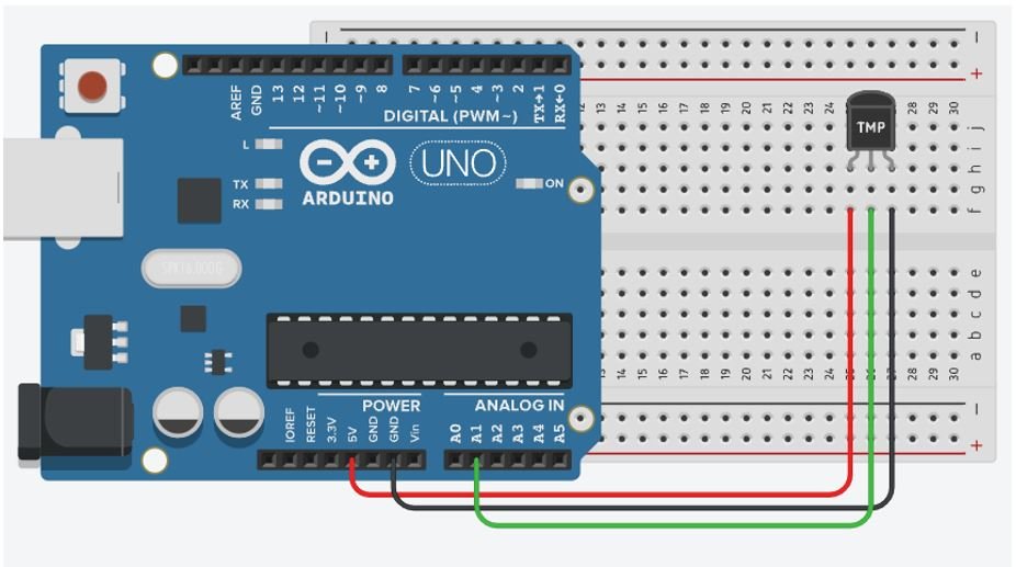
Follow the schematic diagram below to connect the two devices together. As the TMP36 sensor requires an operating voltage of 2.7-5.5V thus we will connect the Power pin of the sensor with 5V of Arduino UNO. The ADC pin A1 is connected with the Vout terminal of the sensor. You can use any appropriate ADC pin. Moreover, both the devices will have their grounds in common.
Obtaining Temperature Readings from TMP36
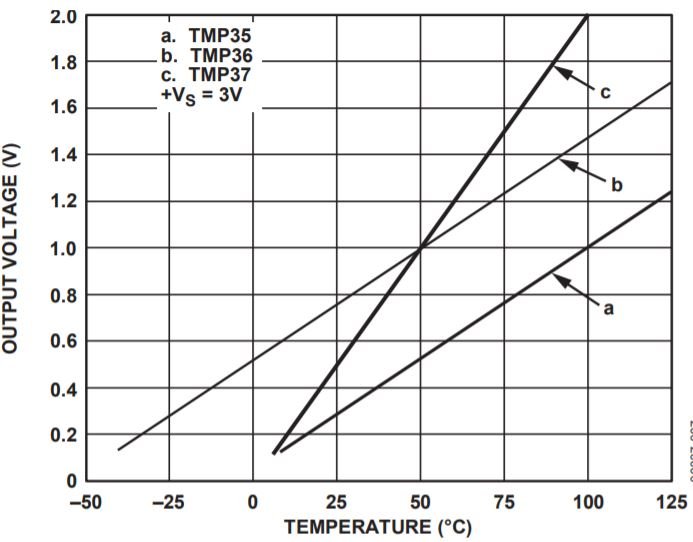
In order to obtain a reading from the TMP36 sensor, we will connect it with Arduino UNO as discussed in the above section. The Vout pin of the sensor when connected with the ADC pin of Arduino UNO will give output voltage readings that will be directly proportional to the temperature (°C ). The graph below is taken from the TMP36 datasheet where the ‘b’ line represents the linear nature of Vout and Temperature.
To convert the output voltage to temperature in degree Celsius we will use the following formula following the linear nature of the two variables.
Temp (°C) = (Vout – 0.5) * 100
In this formula the -0.5 indicates the 0.5V (500mV) offset that the TMP36 sensor has. Additionally, as the sensor has a scaling factor of 10mV/°C that is why we multiply (Vout-0.5) with 100. Plugging in the value for output voltage we can easily obtain the temperature reading in degree Celsius.
However, while programming Arduino UNO with TMP36 sensor we will use analogRead() function that will give us the ADC reading from the sensor. It will be a digital value between 0 and 1023. We will have to convert it into analog output voltage. For this, we have to multiply the ADC digital value with resolution of Arduino ADC which is 5/1024 or 3.3/1024 depending whether you are powering the sensor with 5V or 3.3V. It will provide output in the form of voltage between 0-5V or 0-3.3V according to your Arduino board. As we are using 5V Arduino, hence, to find Vout we will use the following formula:
Vout = (ADC sensor reading)* 5/1024
All of this will be done in the program sketch.
Arduino Sketch: Displaying Temperature Readings in Serial Monitor
Open your Arduino IDE and go to File > New to open a new file. Copy the code given below in that file and save it.
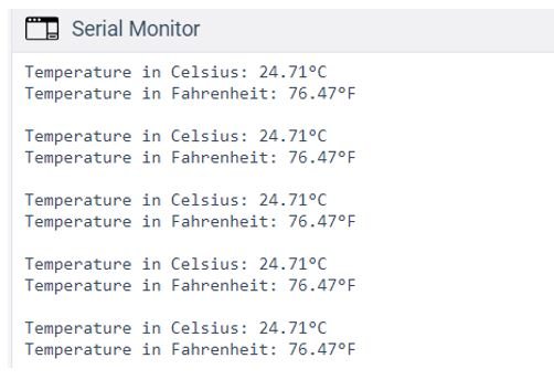
This sketch will be able to display the temperature readings in the serial monitor in both degree Celsius and Fahrenheit.
#define sensor_pin A1

void setup() {
  Serial.begin(115200);
}

void loop() {
  int sensor_data = analogRead(sensor_pin);
  float voltage = sensor_data * (5.0 / 1024.0);

  float temperature_Celsius = (voltage - 0.5) * 100;
  Serial.print("Temperature in Celsius: ");
  Serial.print(temperature_Celsius);
  Serial.print(char(176));
  Serial.println("C");

  float temperature_Fahrenheit = (temperature_Celsius * 9.0 / 5.0) + 32.0;
  Serial.print("Temperature in Fahrenheit: ");
  Serial.print(temperature_Fahrenheit);
  Serial.print(char(176));
  Serial.println("F");

  Serial.println();
  delay(1000);
}
How the Code Works?
Firstly we will define the ADC pin that we connected with Vout of the TMP36 sensor. It is A1 in our case.
#define sensor_pin A1
Inside the setup() function we will open the serial communication at a baud rate of 115200.
void setup() {
  Serial.begin(115200);
}
Inside the infinite loop() function, we will first find out the ADC value using analogRead(). We will pass the ADC pin connected to the sensor as an argument inside it. This will be stored in the integer variable sensor_data.
int sensor_data = analogRead(sensor_pin);Next, we will calculate the analog voltage by multiplying the value stored in the ‘sensor_data’ variable with 5/1024. As we are connecting the +V pin of the sensor with 5V from Arduino hence we are multiplying by 5/1024. If using 3.3V to power up instead, multiply the ADC value acquired from the sensor with 3.3/1024.
float voltage = sensor_data * (5.0 / 1024.0);To calculate the temperature in degree Celsius from the analog voltage, we will use the following formula that we discussed before:
float temperature_Celsius = (voltage - 0.5) * 100;Additionally, to find the temperature reading in Fahrenheit, we will do the following calculation:
float temperature_Fahrenheit = (temperature_Celsius * 9.0 / 5.0) + 32.0;Now, we will print these values in the serial monitor with a delay of 1 second.
float temperature_Celsius = (voltage - 0.5) * 100;
  Serial.print("Temperature in Celsius: ");
  Serial.print(temperature_Celsius);
  Serial.print(char(176));
  Serial.println("C");

  float temperature_Fahrenheit = (temperature_Celsius * 9.0 / 5.0) + 32.0;
  Serial.print("Temperature in Fahrenheit: ");
  Serial.print(temperature_Fahrenheit);
  Serial.print(char(176));
  Serial.println("F");

  Serial.println();
  delay(1000);
Demonstration
Choose the correct board and COM port before uploading your code to the board.
Go to Tools > Board and select Arduino UNO

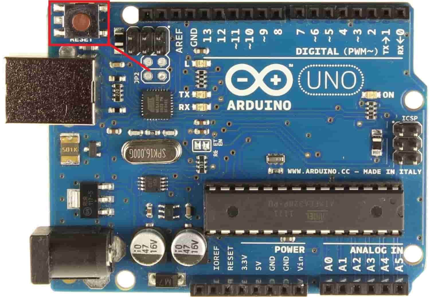
Next, go to Tools > Port and select the appropriate port through which your board is connected. Click on the upload button to upload the code into the Arduino development board. After you have uploaded your code to the Arduino press its RST button.
In your Arduino IDE, open up the serial monitor and you will be able to see the various temperature readings after every second.
Displaying TMP36 Sensor Readings on 16×2 LCD
In this section, we will display the same TMP36 sensor readings which we previously printed on the serial monitor but now on a 16×2 LCD display. We have a dedicated tutorial regarding interfacing 16×2 LCD display with Arduino with some example sketches. Have a look at it before proceeding further for a better understanding of the LCD.
Recommended Reading: 16×2 LCD Interfacing with Arduino – Explained with Example Codes
There are two types of pins on the whole 16×2 LCD module. Some pins are used to send to 16×2 LCD and some are command pins. In other words, every pin has a role in controlling a single pixel on the display.16 x 2 LCD has sixteen columns and two rows. That means, it can display sixteen characters per row and it has two such rows.
Pin out of 16×2 LCD
The diagram shows the pin configuration of a 16×2 LCD display. It has sixteen pins.

- D0 – D7: Pin number 7-14 are data bus lines that are used to send data from Arduino which you want to display on LCD. With these 8 data lines, data can be transferred either in an 8-bit format or in a 4-bit format. In a 4-bit format, only upper four bits (D4-D7) are used to send data from Arduino to LCD. The full byte is transmitted in two successive transmissions. A 4-bit format is used to save GPIO pins of Arduino. Because fewer GPIO pins of Arduino will be required to transfer data.
- Contrast Select (VEE): It will help to control the contrast of PIXELS according to the 16X2 LCD light.
- RS: This pin is known as a register select pin. It helps to toggle the command/data register.
- R/W: The signal on this pin will decide whether it is going to read from LCD or write on it.
- EN: Enable pin will help to transfer the instruction from the data pins and another command pin to the LCD. It act as permission to internal registers.
- VSS: It’s a ground pin for common grounds.
- VCC: The power pin will use for voltage input to the 16X2 LCD.
In Arduino, we don’t need to worry about controlling these data lines and control registers. Because Arduino provides rich library resources. LCD library comes with Arduino IDE by default when we install it.
16×2 LCD Module interfacing with Arduino and TMP36 Sensor
Now we will learn how to connect a 16×2 LCD module with Arduino and TMP36 sensor to display readings.
Required Components:
- Arduino
- TMP36 Sensor
- 16×2 LCD
- 220 ohm resistor
- Connecting wires
- Breadboard
Follow the table below to make the connection diagram accordingly.
Connections between 16×2 LCD and Arduino:
| 16×2 LCD | Arduino UNO |
| D4-D7 | 5, 4, 3, 2 |
| E | 11 |
| RS | 12 |
| VEE | GND |
| VCC | 5V |
| LED+ | 5V |
| LED- | GND with 220-ohm resistor |
| GND | GND |
The connections between the TMP36 sensor and Arduino UNO are the same as we did previously.
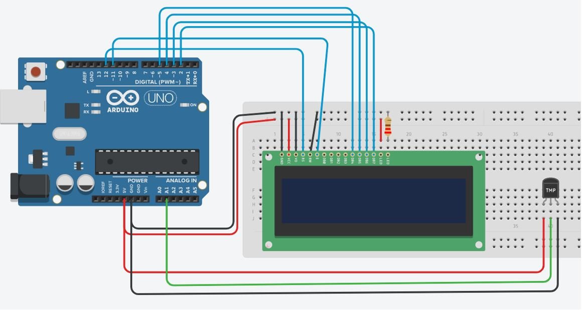
Follow the schematic diagram below to connect all three devices properly. We are following the same connections as specified in the table.
Schematic Diagram
Arduino Sketch: Displaying Temperature Readings from TMP36 Sensor on 16×2 LCD
Open your Arduino IDE and go to File > New to open a new file. Copy the code given below in that file and save it.
This sketch will be able to display the temperature readings (both degree Celsius and Fahrenheit) on the 16×2 LCD and update them to current ones after every second.
#include<LiquidCrystal.h>

const int sensor_pin = A1;
LiquidCrystal lcd(12, 11, 5, 4, 3, 2);

void setup()
{
 lcd.begin(16, 2);

}

void loop()
{
  int sensor_data = analogRead(sensor_pin);
  float voltage = sensor_data * (5.0 / 1024.0);

  float temperature_Celsius = (voltage - 0.5) * 100;

  float temperature_Fahrenheit = (temperature_Celsius * 9.0 / 5.0) + 32.0;

  delay(1000);

  lcd.setCursor(0,0);
  lcd.print("Temperature");
  lcd.setCursor(0,1);
  lcd.print(temperature_Celsius);
  lcd.setCursor(5,1);
  lcd.print(char(178));
  lcd.print("C");

  lcd.print(" ");
  lcd.print(temperature_Fahrenheit);
  lcd.setCursor(12,1);
  lcd.print(char(178));
  lcd.print("F");
}
How the Code Works?
Most of the code is the same as the one in the previous sketch. We have incorporated a 16×2 LCD now. We will display the temperature readings on the LCD.
Firstly, we will include the library necessary for the functionality of the LCD. This library contains prototypes and function definitions that are used to control display.
#include<LiquidCrystal.h>Then, define the ADC pin connected with the TMP36 sensor.
const int sensor_pin = A1; The next most important thing is the declaration of Arduino pins that are connected with the LCD. To define connections, we use the following line of code. This line creates a LiquidCrystal object and lcd is a name of the object that we are going to use to call LCD functions. You can also use any other name.
LiquidCrystal lcd(rs, en, d4, d5, d6, d7)In our case, the pins are 12, 11, 5, 4, 3, and 2 respectively.
LiquidCrystal lcd(12, 11, 5, 4, 3, 2);Till now, we have defined the LCD connection and included its library. After that, we must define the size of the LCD. Inside the setup() function we will call lcd.begin(). This routine is used to define the size of an LCD. The first argument to this function is a number of rows and the second argument is a number of columns. For instance, this line declares the size as 16 columns and 2 rows. That means 16×2 size.
void setup()
{
 lcd.begin(16, 2);
}
Inside the loop() function we will obtain the ADC reading and calculate the analog voltage value from it. Then we will use this voltage value to calculate the temperature in both degrees Celsius and Fahrenheit according to the formulas below:
  int sensor_data = analogRead(sensor_pin);
  float voltage = sensor_data * (5.0 / 1024.0);

  float temperature_Celsius = (voltage - 0.5) * 100;

  float temperature_Fahrenheit = (temperature_Celsius * 9.0 / 5.0) + 32.0;
We will display both these readings on the 16×2 LCD. These values will get updated to new ones after every second.
  lcd.setCursor(0,0);
  lcd.print("Temperature");
  lcd.setCursor(0,1);
  lcd.print(temperature_Celsius);
  lcd.setCursor(5,1);
  lcd.print(char(178));
  lcd.print("C");

  lcd.print(" ");
  lcd.print(temperature_Fahrenheit);
  lcd.setCursor(12,1);
  lcd.print(char(178));
  lcd.print("F");
Demonstration
Choose the correct board and COM port before uploading your code to the board.
Go to Tools > Board and select Arduino UNO
Next, go to Tools > Port and select the appropriate port through which your board is connected. Click on the upload button to upload the code into the Arduino development board. After you have uploaded your code to the Arduino press its RST button.
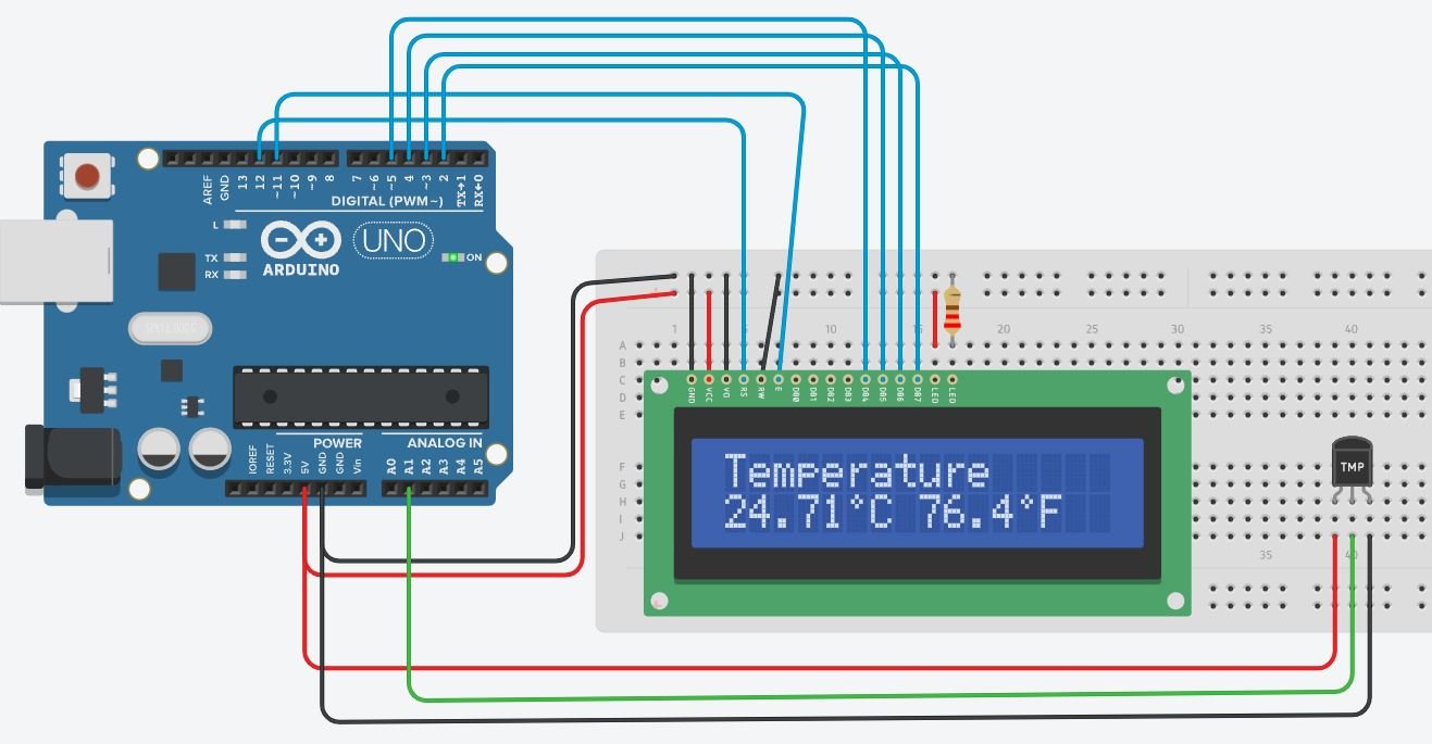
The 16×2 LCD will start displaying the temperature readings.
Conclusion
In conclusion, we looked upon the TMP36 sensor and its programming with the Arduino development board. We have learned how to obtain temperature readings from the TMP36 sensor in both degrees Celsius and Fahrenheit and used two sketches to program our Arduino board to display them in the serial monitor as well on a 16×2 LCD.
For more articles related to temperature sensors with Arduino UNO follow the links below: