Temperature Sensors are used in almost every other device. They are one of the fundamental components required in nearly every industry known to us. It is quite popular among hobbyists and consumer products. LM35 is a temperature sensor introduced by Texas Instruments. It works by producing an analog signal with respect to the temperature at the rate of 10mV/0C. It is a small, in-budget component that is calibrated in Centigrade, unlike other sensors that are calibrated in Kelvin. Its key features like low impedance, linear analog output, and accurate centigrade calibration make its interfacing quite simple with the microcontroller units.
In this tutorial, we will explain the pin configuration, specifications, features, interfacing with Arduino, and applications of an LM35 temperature sensor.
LM35 Temperature Sensor Pinout
The following diagram shows the pinout of the LM-35 Temperature Sensor:

Pin Configuration
Let us discuss the pinout of the LM-35 Temperature Sensor. The pin configuration detail in tabular is mentioned below:
| Pin Number | Pin Name | Function |
|---|---|---|
| 1 | VCC | Positive supply pin |
| 2 | OUT | Analog Output pin |
| 3 | Ground | Ground pin |
LM35 Features and Specifications
- Operational Voltage: 4 – 30 Volts
- Output Voltage:-1 – 6 Volts
- Output Current: 10 mA
- Operating Temperature: -550C -1500C
- Output Impedance: 0.1 ohms for 1mA load
- Drain Current: > 60 uA
- Sink Current: 1 uA
- Accuracy: 0.50C at 250C
Detailed Features
Some of the detailed features are listed below:
- LM-35 is calibrated in Centigrade instead of Kelvin for convenience.
- The trimming and calibration are performed at the wafer level which makes it cost-effective.
- It has a Linear Scale Factor of 10 mV/0C.
- LM-35 has a low self-heating value i.e. 0.080C in still air.
- No external calibration or trimming is required to provide a typical accuracy of ±¼°C.
- It is used with single power supplies.
- It comes in 4 different packages i.e. TO-CAN, TO-92, SOIC, and TO-220.
- It has a low nonlinearity factor which makes it a precise device.
LM35 with Arduino and 16×2 LCD
This section deals with the interfacing of an Arduino microcontroller to the LM35 Temperature Sensor and 16×2 LCD. We will measure the analog output voltage of the temperature sensor with analog pins of Arduino using the AnalogRead function and display the measured voltage value on 16×2 LCD. If you don’t know how to use an LCD and Analog pin of Arduino, you can read these in-depth guides:
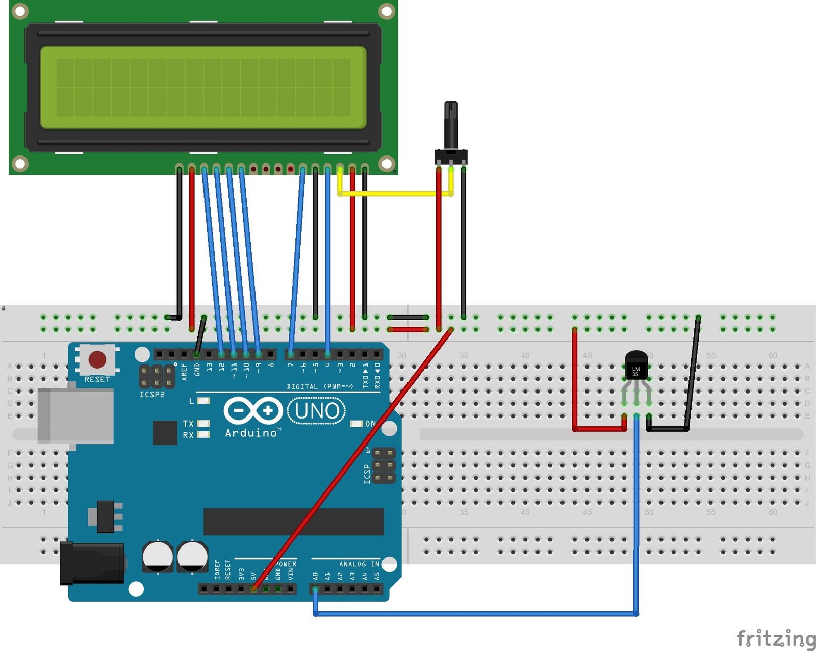
Connection Diagram
- Connect the power supply pins (GND and VCC) to the ground and the 5 Volts pin of the Arduino.
- Also, connect the Analog output pin of the LM35 temperature sensor to the analog pin (A0) of the Arduino.
- Connect the 4-bit LCD (16×2) to the Arduino. The LCD is also powered using Arduino’s 5 volts supply pin. The LCD screen will display the temperature measured by the sensor.
The following schematic is provided to make circuit diagram for Arduino, LM35 and 16×2 LCD.
The following table lists connections of 16×2 LCD and Arduino:
| 16X2 LCD | Arduino |
|---|---|
| D4 – D7 | 9, 10, 11, 12 |
| E | 7 |
| RS | 4 |
| VEE | POT (Middle Leg) |
| VSS | Ground |
| VDD | +5V |
| D+ | +5V |
| D- | Ground |
The following table lists connections between LM35 and Arduino:
| LM35 | Arduino |
|---|---|
| Vcc | +5V |
| GND | GND |
| Vout | A0 |
Arduino Code
/*LM35 temperature sensor with Arduino */

#include<LiquidCrystal.h> //include LCD library
LiquidCrystal lcd(4,7,9,10,11,12); //define Arduino pins used with 16x2 LCD
// Give symbolic name to A0 pin to connect LM35 sensor output
#define LM35_Sensor A0

//Create a symbol for degree notation
byte degree_symbol[8] =
              {
                0b00011,
                0b00011,
                0b00000,
                0b00000,
                0b00000,
                0b00000,
                0b00000,
                0b00000
              };

// Initialize 16x2 LCD and create symbol
void setup()
{
  lcd.begin(16,2);
  lcd.createChar(1, degree_symbol);
  lcd.setCursor(0,0);
  lcd.print("LM35");
  lcd.setCursor(5,0);
  lcd.print("Sensor   ");
  delay(1000);
  lcd.clear();
}

void loop()
{
  /*Read analog voltage signal from A0 pin and convert to temperature*/
     float analog_value=analogRead(LM35_Sensor);
     float temp_degree=analog_value*(5.0/1023.0)*100;
     delay(10);

  /*Display measured temperature on 16x2 LCD*/
    lcd.clear();
    lcd.setCursor(2,0);
    lcd.print("Temperature");
    lcd.setCursor(4,1);
    lcd.print(temp_degree);
    lcd.write(1);
    lcd.print("C");
    delay(1000);
}
How Code Works?
Headers and Declaration
The first step of the Arduino code is to include the libraries required to run the sketch. The next is the definition of the pins. Pins 7, 6, 5, 4, 3, and 2 are connected to the LCD for the interface, and A0 is connected to the analog pin of the temperature sensor.
/*LM35 temperature sensor with Arduino */

#include<LiquidCrystal.h> //include LCD library
LiquidCrystal lcd(4,7,9,10,11,12); //define Arduino pins used with 16x2 LCD
// Give symbolic name to A0 pin to connect LM35 sensor output
#define LM35_Sensor A0
The Degree sign is developed using the custom character method. The code is provided above.
//Create a symbol for degree notation
byte degree_symbol[8] =
              {
                0b00011,
                0b00011,
                0b00000,
                0b00000,
                0b00000,
                0b00000,
                0b00000,
                0b00000
              };
Void Setup
The void setup function in the code will display the introduction message i.e. “Digital Thermometer ”. After displaying the message it will give a delay of 4000 milliseconds.
// Initialize 16x2 LCD and create symbol
void setup()
{
  lcd.begin(16,2);
  lcd.createChar(1, degree_symbol);
  lcd.setCursor(0,0);
  lcd.print("LM35");
  lcd.setCursor(5,0);
  lcd.print("Sensor   ");
  delay(1000);
  lcd.clear();
}
void loop
The void loop block will read the analog signal given by the analog pin of the sensor through the analogRead function. The digital output value will be stored in the variable name “analog_value”.
The analog reading will be converted using the Arduino’s ADC resolution and a conversion factor of 10mV per celsius degree centigrade.
the result will be stored in the float variable Temperature. After a delay of 10 milliseconds, the LCD will display the temperature on to the screen in degree centigrade.
void loop()
{
  /*Read analog voltage signal from A0 pin and convert to temperature*/
     float analog_value=analogRead(LM35_Sensor);
     float temp_degree=analog_value*(5.0/1023.0)*100;
     delay(10);

  /*Display measured temperature on 16x2 LCD*/
    lcd.clear();
    lcd.setCursor(2,0);
    lcd.print("Temperature");
    lcd.setCursor(4,1);
    lcd.print(temp_degree);
    lcd.write(1);
    lcd.print("C");
    delay(1000);
}
Code Output
Now copy the above code and upload the code to the Arduino board using Arduino IDE. The LM35 temperature sensor will sense the air temperature and will produce a respective output analog signal proportional to the temperature. 10 mV of the analog output voltage represents 10C. This analog signal will be measured with the Arduino ADC channel (A0). Arduino carries out the calculations, and the temperature is displayed on the LCD.
To see the temperature change, bring the circuit into a heated room. The new temperature will be displayed by the LCD screen.
Applications
- HVAC systems
- Power applications
- Medical Systems
- Industrial equipment
- Computer Systems
Related Articles:
- LM35 Temperature Sensor with 7-Segment Display using Pic Microcontroller
- TMP36 Low Voltage Temperature Sensor
- Temperature sensor using PIC16F877A microcontroller
- LM35 Temperature Sensor with ESP32 – Web Server
- DS18B20 Temperature Module interfacing with arduino
- DHT22 Temperature and Humidity Sensor Interfacing with Pic Microcontroller
- BMP280 Barometric Pressure and Temperature Sensor Module
- XBee Based Temperature and Gas Monitoring System Using Pic Microcontroller
- Automatic Temperature controller using pic microcontroller
- IOT based temperature data logger using esp8266 and pic microcontroller
- thermistor interfacing with arduino temperature meter
Please Make a LM35 Temperature Sensor with 7-Segment Positive and Negative Temperature Measurement .