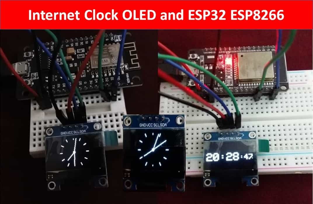
In this tutorial, we will create two types of IoT based clocks such as Analog and Digital using OLED display and ESP32 and ESP8266 NodeMCU development boards. We will use the NTP server to acquire the current time and display it on the OLED for the digital clock in a 24-hour format consisting of HH:MM: SS. For the Analog clock, we will first build the clock face, hour, minute, and second hands and accordingly acquire the time from the NTP server to display the Analog clock appropriately. You can further enhance this project to display the date with the clock as well. This user guide is applicable for both ESP32 and ESP8266 development boards.
In a previous article, we built an Internet Based Digital Clock using ESP32 and MAX7219 Dot Matrix Display. You may want to have a look at it as well.
This user guide is divided into the following sections:
- Working Process for ESP32/ESP8266 OLED Clock
- Setting up Arduino IDE (installing libraries) for OLED based Clock
- Analog Clock with OLED, ESP32 and ESP8266
- Digital Clock with OLED, ESP32 and ESP8266
Recommended Components
The following components are used in this project or are helpful for building it with the ESP32.
| Component | How it’s used in this project | Buy on Amazon |
|---|---|---|
| ESP32 Development Board (DevKit V1) | The main controller that runs the project code and connects to the components. | Check Price |
| ESP8266 NodeMCU (ESP-12E) | Alternative Wi-Fi board you can use to follow this tutorial with the ESP8266. | Check Price |
| Micro USB Cable | Connects the ESP32 to your computer for programming and power. | Check Price |
| Breadboard | Lets you build the circuit and wire up parts without soldering. | Check Price |
| Jumper Wires | Make the connections between the ESP32 and the components on the breadboard. | Check Price |
| 0.96″ SSD1306 OLED Display | Shows the sensor readings locally on an I2C OLED screen. | Check Price |
As an Amazon Associate we earn from qualifying purchases. Prices and availability are accurate as of the date/time indicated and are subject to change.
Working Process of IoT Based ESP32/ESP8266 OLED Clock
Our aim is to build two types of OLED based clocks: Analog and Digital using ESP32 and ESP8266 boards. We will program our ESP boards using the Arduino IDE and acquire the current time from the NTP server. There will be two Arduino sketches. One for the Analog clock and the other for the Digital clock. In both of the sketches, you can use either ESP32 or ESP8266 development board to build the clock. You will however require a steady internet connection for this project. Now let us see how to obtain the current time from the NTP server.
Getting Time from NTP Server
NTP is a standard internet protocol that is widely used to synchronize computer clocks to a reference network. With a precision of approximately 50ms over the wide-area network (WAN) and less than 5ms over the local area network (LAN), it synchronizes epoch/current time of all networked devices to the UTC.
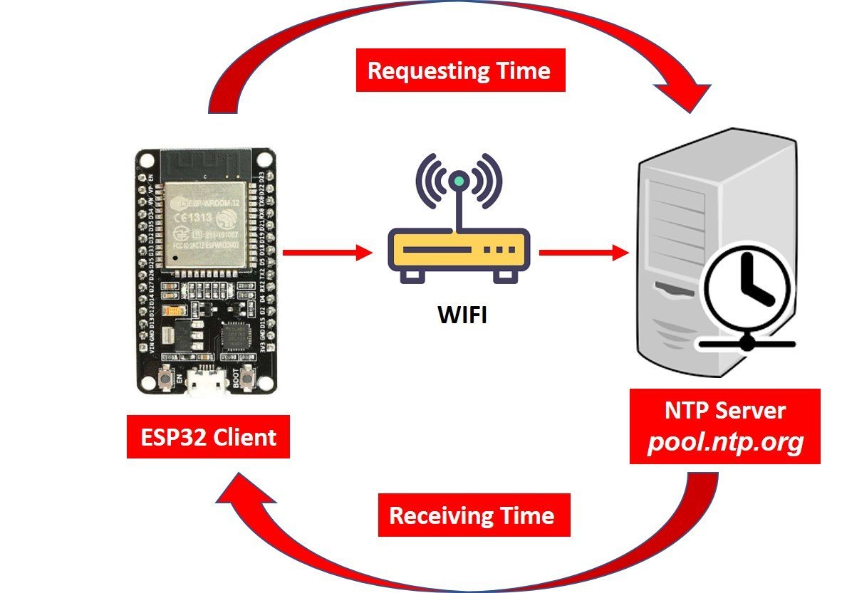
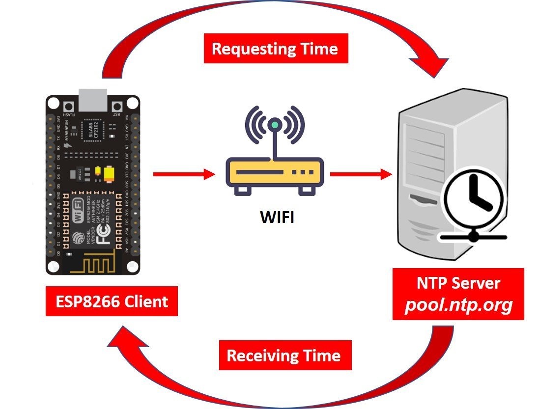
To get the current time with ESP32 or ESP8266 through the NTP server, the server will operate in the client-server model. We will use the NTP server: pool.ntp.org which is easily accessible for everyone worldwide. Our ESP development board will be the client and will connect to a time server using the NTPClient library. The server (pool.ntp.org) will be able to connect with the client. After the connection is made, the ESP board will send a request to the server. When the NTP receives the request, it will transmit the time stamp containing the information regarding the time which will be the epoch time.
The Epoch time or the UNIX time is the number of seconds that have passed since the Unix epoch which is 00:00:00 UTC on 1 January 1970, minus leap seconds. In order to access the current time we will use the Arduino time library which will help us convert the epoch time to the current time in hour, minute and seconds.
Related NTP Server articles:
- Getting Epoch/Unix time with ESP32 through NTP server using Arduino IDE
- Epoch/Unix time with ESP8266 NodeMCU through NTP server using Arduino IDE
- Getting Current Date and Time with ESP32 using NTP Server-Client and Arduino IDE
- Current Date and Time with ESP8266 NodeMCU using NTP Server-Client and Arduino IDE
Points to Note
We will upload a program code in our ESP32/ESP8266 board using Arduino IDE which will connect to the NTP server through our local network and we will request the current time. We will use these values to build our analog/digital clocks.
Two things to take into account while accessing the time for your time zone is to look for the Coordinated Universal Time (UTC) offset and the daylight savings offset.
- For the UTC offset, click here to check for your time zone and add the offset in the program code by converting it in seconds.
For example, for the United States the UTC is -11:00 so converting it in seconds it becomes:
-39600 (-11*60*60).
For Pakistan, the UTC offset is +05:00 so in our code, we will specify the GMT offset which is the same as the UTC offset in seconds as 18000 (5*60*60).
- If your country observes the daylight savings (click here to check) then you will have to incorporate it in the program code by adding 3600 (in seconds) otherwise it will be replaced by a 0. Pakistan does not observe daylight savings so we will add 0 in the daylight offset variable in the code.
SSD1306 0.96 inch OLED Display
OLED stands for organic light-emitting diode. Its name shows that it is a flat light emitting technology that is developed when two organic thin films are connected in series between two electric conductors. When an electric current is supplied to these conductors then the organic compound is made which emits the bright light. Typically, one conductor is the transparent conductor between these two conductors therefore there is no need for any backlight to emits the light. Therefore, this OLED display has improved image quality, full viewing angle, high brightness, better contrast, wide color range, low power consumption, more efficient and reliable as compared to a simple LCD display. It is mainly used in digital display devices such as computer monitors, mobile phones, handheld games, and televisions screens, etc.
Although there are several types of OLED displays available in the market the one which we will be using is the SSD1306 0.96-inch OLED display. The main component of all different types of OLED displays is an SSD1306 controller which uses I2C or SPI protocol to communicate with the microcontrollers. The OLED performs faster in SPI communication but it is popular with I2C communication. The reason for the popularity is the lower number of pins. The OLED displays can vary in size, color, and shape but are primarily programmed in a similar way.
Let us take a look at the OLED display which we will be using in this article. It is called SSD 1306 0.96-inch OLED display which has 128×64 pixels and communicates only via I2C protocol with the ESP development boards. It is cheap and readily available in the market.
Below you can see the pinout of this OLED Display.
Recommended Reading: Monochrome 0.96” OLED Display
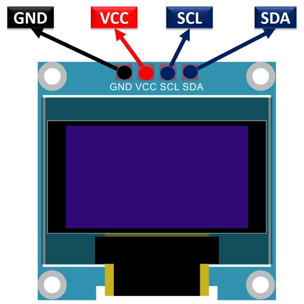
SSD1306 OLED Pinout
There are four pins in this display. Imprinted as VCC, GND, SCL, and SDA respectively. The VCC and GND pins will power the OLED display and will be connected with the ESP board’s power supply pins as they require a driving voltage of 3.3-5V. The SCL and SDA pins are necessary for generating the clock signal and in the transmission of data respectively. Both of these pins will be connected with the I2C pins of the ESP8266 or ESP32 board.
Now let us have a look at the specifications for this model:
| Size | 0.96 inch |
| Terminals | 4 |
| Pixels | 128×64 |
| Communication | I2C only |
| VCC | 3.3V-5V |
| Operating Temperature | -40℃ to +80℃ |
Interfacing SSD1306 OLED Display with ESP8266 and ESP32
As we have seen above, the OLED display has 4 terminals which we will connect with the ESP boards. As the OLED display requires an operating voltage in the range of 3.3-5V hence we will connect the VCC terminal with 3.3V which will be in common with the ESP board. SCL of the display will be connected with the SCL pin of the module and the SDA of the display will be connected with the SDA of the module. The ground of both the devices will be held common.
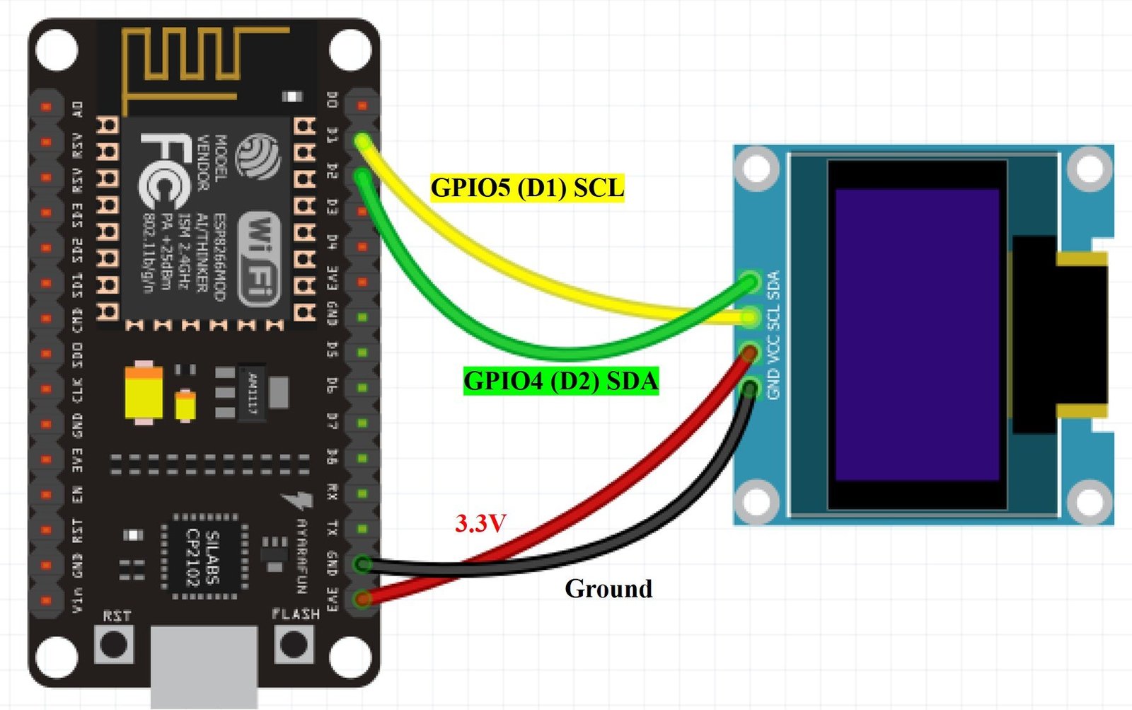
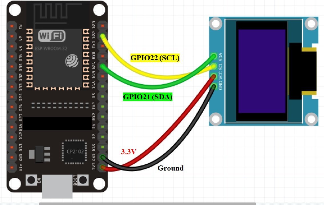
By default, the I2C pin in ESP32 for SDA is GPIO21, and for SCL is GPIO22. Whereas in ESP8266 the default I2C pin for SDA is GPIO4 and for SCL is GPIO5.
The connections between the two devices can be seen below for both the ESP boards.
| ESP32 board | ESP8266 board | SSD1306 OLED Display |
|---|---|---|
| 3.3V | 3.3V | VCC |
| GPIO21(I2C SDA) | GPIO4 (D2) | SDA |
| GPIO22 (I2C SCL) | GPIO5 (D1) | SCL |
| GND | GND | GND |
The I2C pins stated above are set in default. If you want to use any GPIO pins for I2C, you will have to set it in code using SoftI2C().
Components Required:
We will need the following components to connect our ESP8266/ESP32 board with the OLED Display.
- ESP8266 or ESP32 board
- SSD1306 OLED Display
- Connecting Wires
- Breadboard
Follow the schematic diagrams below for both the ESP modules and connect them accordingly.
Schematic ESP8266 with OLED
If you are using ESP8266 NodeMCU for this project, connect the ESP8266 device with OLED as shown in the schematic diagram below:
If you are using ESP32 for this project, connect the ESP32 device with OLED as shown in the schematic diagram below:
Setting up Arduino IDE
We will use Arduino IDE to program our ESP32/ESP8266 development board. Thus, you should have the latest version of Arduino IDE. Additionally, you also need to install the ESP32 and the ESP8266 plugin. If your IDE does not have the plugins installed you can visit the links below:
Installing ESP32 library in Arduino IDE and upload code.
Installing ESP8266 library in Arduino IDE
Installing Libraries
To use the OLED display in our project, we have to install the Adafruit SSD 1306 library and Adafruit GFX library in Arduino IDE. Follow the steps below to successfully install them.
Open Arduino IDE and click on Sketch > Library > Manage Libraries
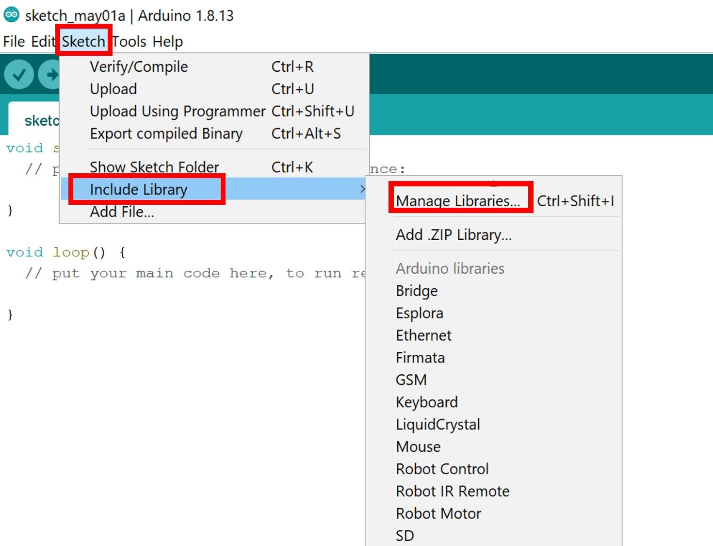
The following window will open up.

Type ‘SSD1306’ in the search tab and install the Adafruit SSD1306 OLED library.

We will also require the Adafruit GFX library which is a dependency for SSD1306. Type ‘Adafruit GFX’ in the search tab and install it as well.
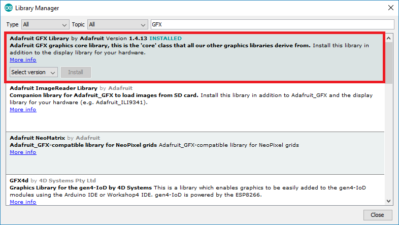
After installing the libraries, restart your IDE.
Building IoT Based ESP32/ ESP8266 OLED Analog Clock
- OLED Display Interfacing with ESP32 – Display Text, Draw shapes and Images
- OLED Display Interfacing with ESP8266 NodeMCU – Display Text, Draw shapes and Images
We will build the face of our Analog clock using the OLED libraries that we previously installed. We will be required to draw circle and lines. You should go through our recommended readings for OLED interfacing with both ESP32 and ESP8266 development boards. It is an in-depth guide where we also discussed how to display simple shapes on the OLED. We will use the same functions here as well to draw the clock face.

Arduino Sketch
Open your Arduino IDE and go to File > New to open a new file. Copy the code given below in that file. This code will work for both ESP32 and ESP8266 development boards. You just need to enter your network credentials as well as specify the GMT and daylight savings offset for your country.
#include <Arduino.h>
#ifdef ESP32
  #include <WiFi.h>
#else
  #include <ESP8266WiFi.h>
#endif
#include <time.h>
#include <SPI.h>
#include <Wire.h>
#include <Adafruit_GFX.h>
#include <Adafruit_SSD1306.h>

Adafruit_SSD1306 display = Adafruit_SSD1306(128, 64, &Wire, -1);

const char* ssid = "Your_SSID";
const char* password = "Your_Password";

int GMTOffset = 18000;  //Replace with your GMT Offset in seconds
int daylightOffset = 0;  //Replace with your daylight savings offset in seconds

void setup() {
Serial.begin(115200);

if(!display.begin(SSD1306_SWITCHCAPVCC, 0x3C)) {
  Serial.println(F("SSD1306 allocation failed"));
  for(;;);
}
  delay(2000);
display.clearDisplay();
display.setTextSize(1);
display.setCursor(0,0);
display.setTextColor(WHITE);

WiFi.begin(ssid, password);
  while (WiFi.status() != WL_CONNECTED) {
    delay(1000);
    Serial.println("Connecting...");
  }

  Serial.println("Connected to Wi-Fi!");

configTime(GMTOffset, daylightOffset, "pool.ntp.org","time.nist.gov");
}
void loop() {
time_t rawtime = time(nullptr);
struct tm* timeinfo = localtime(&rawtime);

int radius = 35;
display.drawCircle(display.width()/2, display.height()/2, 2, WHITE);
//draw clock
for( int i=0; i < 360;i= i + 30 ){
float angle = i ;
angle=(angle/57.29577951) ;
int x1=(64+(sin(angle)*radius));
int y1=(32-(cos(angle)*radius));
int x2=(64+(sin(angle)*(radius-5)));
int y2=(32-(cos(angle)*(radius-5)));
display.drawLine(x1,y1,x2,y2,WHITE);
}

//draw second hand
float angle = timeinfo->tm_sec*6 ;
angle=(angle/57.29577951) ;
int x2=(64+(sin(angle)*(radius)));
int y2=(32-(cos(angle)*(radius)));
display.drawLine(64,32,x2,y2,WHITE);

// draw minute hand
angle = timeinfo->tm_min * 6 ;
angle=(angle/57.29577951) ;
x2=(64+(sin(angle)*(radius-3)));
y2=(32-(cos(angle)*(radius-3)));
display.drawLine(64,32,x2,y2,WHITE);

// draw hour hand
angle = timeinfo->tm_hour * 30 + int((timeinfo->tm_min / 12) * 6 );
angle=(angle/57.29577951) ;
x2=(64+(sin(angle)*(radius-11)));
y2=(32-(cos(angle)*(radius-11)));
display.drawLine(64,32,x2,y2,WHITE);

display.display();
delay(100);
display.clearDisplay();

}
How the Code Works?
We will start off by including the necessary libraries for this project. Firstly we will define the WiFi.h library for ESP32 and ESP8266WiFi.h library for the ESP8266 NodeMCU. These libraries will be used to connect with the local WIFI network and also connect with the NTP server according to the ESP board being used. Next, the time library will help us to achieve the NTP synchronization and get the time. Wire.h will allow us to communicate through the I2C protocol. Whereas the other OLED libraries are the ones which we previously installed and are required for the proper functionality of the OLED display.
#include <Arduino.h>
#ifdef ESP32
  #include <WiFi.h>
#else
  #include <ESP8266WiFi.h>
#endif
#include <time.h>
#include <SPI.h>
#include <Wire.h>
#include <Adafruit_GFX.h>
#include <Adafruit_SSD1306.h>
Then, we will initialize the OLED display by creating an object of Adafruit_SSD1306 and specifying the width, height, I2C instance (&Wire), and -1 as parameters inside it.’ -1′ specifies that the OLED display which we are using does not have a RESET pin. If you are using the RESET pin then specify the GPIO through which you are connecting it with your development board.
Adafruit_SSD1306 display = Adafruit_SSD1306(128, 64, &Wire, -1); Next, we will create two global variables, one for the SSID and the other for the password. These will hold our network credentials which will be used to connect to our wireless network. Replace both of them with your credentials to ensure a successful connection.
const char* ssid = "Your_SSID";
const char* password = "Your_Password";
Now, we will define two variables, the GMT offset and the other for the daylight offset in seconds. We have specified the offsets for Pakistan but you can change them according to your time zone to obtain the correct time.
int GMTOffset = 18000;  //Replace with your GMT Offset in seconds
int daylightOffset = 0;  //Replace with your daylight savings offset in seconds
setup()
Inside our setup() function, we will initialize the serial communication at a baud rate of 112500.
Serial.begin(115200); Moreover, we will also initialize the OLED display by using display.begin(). Make sure you specify the correct address of your display. In our case, it is 0X3C.
if(!display.begin(SSD1306_SWITCHCAPVCC, 0x3C)) {
  Serial.println(F("SSD1306 allocation failed"));
  for(;;);
}
Then, we will clear the buffer by using clearDisplay() on the Adafruit_SSD1306 object.
First, we will set the size of the text using setTextSize() and pass the size as a parameter inside it. Next, we will control the color of the text by using the setTextColor() function and passing WHITE as an argument. We will use the setCursor() function to denote the x and the y axis position from where the text should start.
display.clearDisplay();
display.setTextSize(1);
display.setCursor(0,0);
display.setTextColor(WHITE);
The following section of code will connect the ESP32/ESP8266 module with the local network. We will call WiFi.begin() and pass the SSID and password variables inside it which we defined before.
After a successful connection has been established, the serial monitor will display the message “Connected to Wi-Fi!”
WiFi.begin(ssid, password);
  while (WiFi.status() != WL_CONNECTED) {
    delay(1000);
    Serial.println("Connecting...");
  }

  Serial.println("Connected to Wi-Fi!");
Next, we will use the configTime() function and pass four arguments inside it. The arguments will be the GMT offset, the daylight offset, the NTP server (pool.ntp.org) and the NIST time server respectively. The NTPClient library will obatin the epoch time from the ‘time.nist.gov’ server according to our set GMT offset and daylight savings offset.
configTime(GMTOffset, daylightOffset, "pool.ntp.org","time.nist.gov");loop()
Inside the loop() function we will display the Analog clock by first building its face and then updating it every second. We will use the Arduino time.h library to convert the epoch time to the current time and fetch individual hour, minutes and seconds. First, we will create a tm structure called timeinfo that will be set to the localtime() function. This function takes in the parameter &rawtime.
time_t rawtime = time(nullptr);
struct tm* timeinfo = localtime(&rawtime);
Building the Analog Clock
The next step is to draw the clock face. The following lines of code use trigonometric properties to obtain the x and y coordinates for the lines that we will draw to indicate each hour. We will use a for loop() to draw the face. We will increment the value by 30 each time until the loop reaches 360. Then we will convert the angle from degree to radians by multiplying the angle by π/180 or dividing by 57.29577951 (approximately).
Now to we will display a line on the OLED screen we will use the drawLine() function on the Adafruit_SSD1306 object that is ‘display.’ This function takes in five parameters. The first two parameters are the starting coordinates and the next two parameters are the ending coordinates of the line. Lastly the fifth parameter is the colour of the line. We have passed (x1,y1) as the starting coordinates and (x2,y2) as the ending coordinates of the line in the for() loop. It will be white in colour.
We have defined the radius as 35 and will multiply it with the sin(angle) and then add it to 64 for the starting x coordinate. Likewise, we will multiply the radius with the cos(angle) then subtract it from 32 to get the starting y coordinate. In a similar way, we will obtain the ending x and y coordinates by applying the formulae. These will be used to create the face of the clock.
int radius = 35;
display.drawCircle(display.width()/2, display.height()/2, 2, WHITE);
//draw clock
for( int i=0; i < 360;i= i + 30 ){
float angle = i ;
angle=(angle/57.29577951) ;
int x1=(64+(sin(angle)*radius));
int y1=(32-(cos(angle)*radius));
int x2=(64+(sin(angle)*(radius-5)));
int y2=(32-(cos(angle)*(radius-5)));
display.drawLine(x1,y1,x2,y2,WHITE);
}
Building the hands
The next step is to create the seconds hand of the clock. We will first acquire the seconds from the tm structure by accessing tm_sec and update it to the floating variable called ‘angle.’ This will save the time in seconds multiplied by 6. Next convert this angle to radians and then find the ending coordinates for the line that will represent the second hand. The starting x and y coordinates of the line will be 64 and 32 respectively. These are the centre coordinates of the OLED display.
float angle = timeinfo->tm_sec*6 ;
angle=(angle/57.29577951) ;
int x2=(64+(sin(angle)*(radius)));
int y2=(32-(cos(angle)*(radius)));
display.drawLine(64,32,x2,y2,WHITE);
In a similar manner we will create the minutes hand of the clock. We will first acquire the minutes from the tm structure by accessing tm_min and update it to the floating variable called ‘angle.’ This will save the time in minutes multiplied by 6. Next convert this angle to radians and then find the ending coordinates for the line that will represent the minutes hand. The starting x and y coordinates of the line will be 64 and 32 respectively. These are the centre coordinates of the OLED display.
angle = timeinfo->tm_min * 6 ;
angle=(angle/57.29577951) ;
x2=(64+(sin(angle)*(radius-3)));
y2=(32-(cos(angle)*(radius-3)));
display.drawLine(64,32,x2,y2,WHITE);
Lastly, we will create the hour hand of the clock. We will acquire the hour from the tm structure by accessing tm_hour. The angle variable will be appropriately calculated. Next convert this angle to radians and then find the ending coordinates for the line that will represent the hour hand. The starting x and y coordinates of the line will be 64 and 32 respectively. These are the centre coordinates of the OLED display.
angle = timeinfo->tm_hour * 30 + int((timeinfo->tm_min / 12) * 6 );
angle=(angle/57.29577951) ;
x2=(64+(sin(angle)*(radius-11)));
y2=(32-(cos(angle)*(radius-11)));
display.drawLine(64,32,x2,y2,WHITE);
Now, we will call the display() function on the display object so that the shapes display on the OLED. We will add a delay of 1 second after which the loop() will run again. Additionally ,we will also clear the buffer using clearDisplay() on the display object.
display.display();
delay(100);
display.clearDisplay();
Demonstration
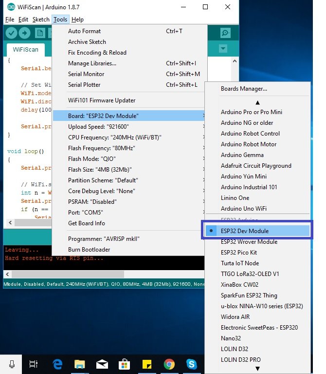
Choose the correct board and COM port before uploading your code to the board. Therefore go to Tools > Board and select ESP32 Dev Module or NodeMCU 1.0.
If you are using ESP32, select the ESP32 Dev module as follows:
If you are using ESP8266 NodeMCU, select the NodMCU module as follows:

Then, go to Tools > Port and select the appropriate port through which your board is connected.

Click on the upload button to upload the code to ESP32 or ESP8266 development board.
After you have uploaded your code to the ESP32 or ESP8266 development board, press its ENABLE/RST button.


If there is no error in the serial monitor then after a few moments, the OLED will start displaying the Analog clock that will update after every second.
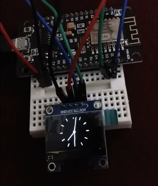
Watch the video for the demonstration below for a better insight.
Building IoT Based ESP32/ESP8266 OLED Digital Clock
Now let us proceed towards the digital clock. This is relatively easier to build than the Analog clock as we do not need the clock face and only the time acquired from the NTP server. We will display hours, minutes, and seconds individually on the OLED display in the 24 hour HH:MM: SS format.

Arduino Sketch
Open your Arduino IDE and go to File > New to open a new file. Copy the code given below in that file. This code will work for both ESP32 and ESP8266 development boards. You just need to enter your network credentials as well as specify the GMT and daylight savings offset for your country.
#ifdef ESP32
  #include <WiFi.h>
#else
  #include <ESP8266WiFi.h>
#endif
#include <time.h>
#include <SPI.h>
#include <Wire.h>
#include <Adafruit_GFX.h>
#include <Adafruit_SSD1306.h>

Adafruit_SSD1306 display = Adafruit_SSD1306(128, 64, &Wire, -1);

const char* ssid = "Your_SSID";
const char* password = "Your_Password";

int GMTOffset = 18000;  //Replace with your GMT Offset in seconds
int daylightOffset = 0;  // Replace with your daylight savings offset in seconds

void setup() {
Serial.begin(115200);

if(!display.begin(SSD1306_SWITCHCAPVCC, 0x3C)) {
  Serial.println(F("SSD1306 allocation failed"));
  for(;;);
}
  delay(2000);
display.clearDisplay();
display.setTextSize(1);
display.setCursor(0,0);
display.setTextColor(WHITE);

WiFi.begin(ssid, password);
  while (WiFi.status() != WL_CONNECTED) {
    delay(1000);
    Serial.println("Connecting...");
  }

  Serial.println("Connected to Wi-Fi!");

configTime(GMTOffset, daylightOffset, "pool.ntp.org","time.nist.gov");
}


void loop() {
time_t rawtime = time(nullptr);
struct tm* timeinfo = localtime(&rawtime);

Serial.print("Time: ");
Serial.print(timeinfo->tm_hour);
Serial.print(":");
Serial.print(timeinfo->tm_min);
Serial.print(":");
Serial.println(timeinfo->tm_sec);

display.clearDisplay();
display.setTextSize(3);
display.setTextColor(WHITE);
display.setCursor(0,25);
display.print(timeinfo->tm_hour);
display.print(":");
if( timeinfo->tm_min <10)
display.print("0");
display.print(timeinfo->tm_min);

display.setTextSize(2);
display.setCursor(90,30);
display.print(":");
if( timeinfo->tm_sec <10)
display.print("0");
display.print(timeinfo->tm_sec);
display.display();

delay(1000);

}
How the Code Works?
Most of the initial code is the same as that for the Analog Clock so we will focus on the parts which are different.
loop()
We will use the Arduino time.h library to convert the epoch time to the current time and fetch individual hour, minutes and seconds. First, we will create a tm structure called timeinfo that will be set to the localtime() function. This function takes in the parameter &rawtime. Then we will print the individual hour , minute and second in the serial monitor in a format HH:MM:SS. This is achieved by accessing the pointer timeinfo of the tm structure and obtaining individual hour, min and second by using the arrow operator on tm_hour, tm_min and tm_sec accordingly.
time_t rawtime = time(nullptr);
struct tm* timeinfo = localtime(&rawtime);

Serial.print("Time: ");
Serial.print(timeinfo->tm_hour);
Serial.print(":");
Serial.print(timeinfo->tm_min);
Serial.print(":");
Serial.println(timeinfo->tm_sec);
Displaying Digital Clock on OLED
Now we will display these same hour, min and second on the OLED display. First , we will clear the buffer then set the size of the text using setTextSize() and pass the size as a parameter inside it. Next, we will control the color of the text by using the setTextColor() function and passing WHITE as an argument. We will use the setCursor() function to denote the x and the y axis position from where the text should start. By using print() on the display object we will pass timeinfo->tm_hour to display the current hour. This will be followed by “:” In a similar manner we will display the minute by using print() on the display object we will pass timeinfo->tm_min to display the current minute. This will again be followed by a “:”
Now, we will set the font size to 2 to display the seconds otherwise the clock won’t be properly displayed on the OLED due to its size. Set the cursor as well. Now, by using print() on the display object we will pass timeinfo->tm_sec to display the current second. Additionally, we will also add a condition for the minute and second. If the number is less than 10 then we will display the min/sec proceeded by a 0.
Moreover, we will add a delay of 1 second after which the loop() will run again so that the clock updates every second.
display.clearDisplay();
display.setTextSize(3);
display.setTextColor(WHITE);
display.setCursor(0,25);
display.print(timeinfo->tm_hour);
display.print(":");
if( timeinfo->tm_min <10)
display.print("0");
display.print(timeinfo->tm_min);

display.setTextSize(2);
display.setCursor(90,30);
display.print(":");
if( timeinfo->tm_sec <10)
display.print("0");
display.print(timeinfo->tm_sec);
display.display();

delay(1000);
Demonstration
Choose the correct board and COM port before uploading your code to the board. Therefore go to Tools > Board and select ESP32 Dev Module or NodeMCU 1.0.
If you are using ESP32, select the ESP32 Dev module as follows:
If you are using ESP8266 NodeMCU, select the NodMCU module as follows:
Then, go to Tools > Port and select the appropriate port through which your board is connected.
Click on the upload button to upload the code to ESP32 or ESP8266 development board.
After you have uploaded your code to the ESP32 or ESP8266 development board, press its ENABLE/RST button.
If there is no error in the serial monitor then after a few moments, the OLED will start displaying the Digital clock that will update after every second.
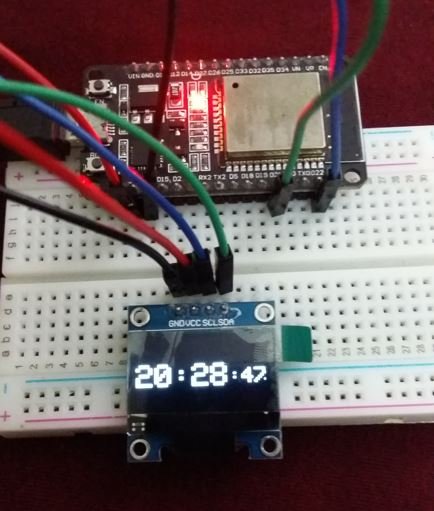
Watch the video for the demonstration below for a better insight.
Hi, im trying to do your projet to make an old clock radio work with a oled display.
But the format doesnt match cause my minutes digits has to be separated, do you know how i can put a blank space between the two minute digits to make it fit?
Thank a lot, im learnig a lot, but this may be complicated for a noob like me!