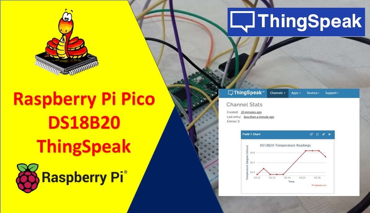
In this user guide, we will learn how to publish DS18B20 sensor readings to ThingSpeak using Micropython, Raspberry Pi Pico, and ESP-01 module. We will use Thonny IDE to program our Raspberry Pi Pico board which will be connected to a temperature sensor. Our main aim is to transmit these sensor readings to ThingSpeak easily and interactively demonstrate them.
Recommended Components
The following components are used in this project or are helpful for getting started with Raspberry Pi Pico development.
| Component | How it’s used in this project | Buy on Amazon |
|---|---|---|
| Raspberry Pi Pico | The RP2040 microcontroller board used in this tutorial. | Check Price |
| DS18B20 Temperature Sensor | Digital temperature sensor whose readings are sent to ThingSpeak. | Check Price |
| ESP8266 ESP-01 Module | Wi-Fi module that connects the Pico to the internet. | Check Price |
| Resistor Kit | Includes the 4.7k ohm pull-up resistor for the DS18B20 data line. | Check Price |
| Jumper Wires | Male-to-male / male-to-female wires for the connections. | Check Price |
As an Amazon Associate we earn from qualifying purchases. Prices and availability are accurate as of the date/time indicated and are subject to change.
We have similar guides with DHT22 and BME280:
- Raspberry Pi Pico Send DHT22/DHT11 Sensor Readings to ThingSpeak
- Raspberry Pi Pico Send BME280 Readings to ThingSpeak
Raspberry Pi Pico does not support Wi-Fi capabilities hence we have to use a separate Wi-Fi module to enable Wi-Fi connectivity. Therefore, we will interface and program ESP-01 Wi-Fi module with Raspberry Pi Pico to enable Wi-Fi features. We will use Thonny IDE to program Raspberry Pi Pico with ESP-01 and DS18B20 in MircoPython. We will use AT commands through the serial port that is UART to configure the ESP-01 Wi-Fi module.
The following content will be covered in this article:
- Introduction to DS18B20 sensor
- Connecting Raspberry Pi Pico with DS18B20 and ESP-01 Wi-Fi module
- Getting ThingSpeak API Ready
- Publish to multiple fields of sensor readings to ThingSpeak (Temperature and pressure)
Prerequisites
Before we start this lesson make sure you are familiar with and have the latest version Python 3 in your system, have set up MicoPython in Raspberry Pi Pico, and have a running Integrated Development Environment(IDE) in which we will be doing the programming. We will be using the same Thonny IDE as we have done previously when we learned how to blink and chase LEDs in micro-python. If you have not followed our previous tutorial, you check here:
If you are using uPyCraft IDE, you can check this getting started guide:
Recommended Readings:
- DS18B20 Temperature Sensor with Raspberry Pi Pico using MicroPython
- Interface ESP8266 WiFi Module with Raspberry Pi Pico
DS18B20 Introduction
It is a temperature sensor that is single wire programmable in nature. It is widely used to measure the temperature of chemical solutions and substances which are present in a hard environment. One of the advantages of using this sensor is that we only require a single pin of our Raspberry Pi Pico boards to transfer data. Thus, it is extremely convenient to use with the micro-controller as we can measure multiple temperatures by using the least number of pins on our development board.
The table below shows some key characteristics of the ds18b120 sensor.
| Feature | Value |
|---|---|
| Operating Voltage | 3V-5V |
| Temperature Range | -55°C to +125°C |
| Accuracy | ±0.5°C |
| Output Resolution | 9bit to 12bit |
Pinout Diagram
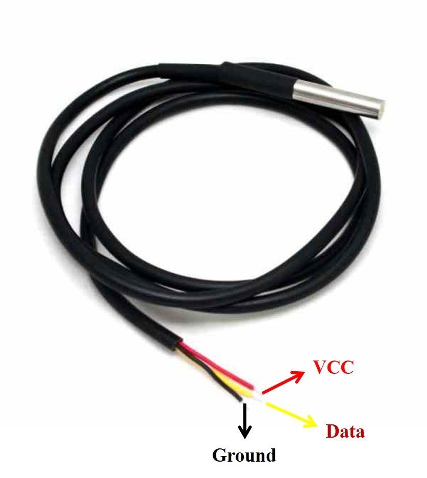
A waterproof version of this sensor is also available in the market. The following figures show the pinout of the DS18B20 sensors.
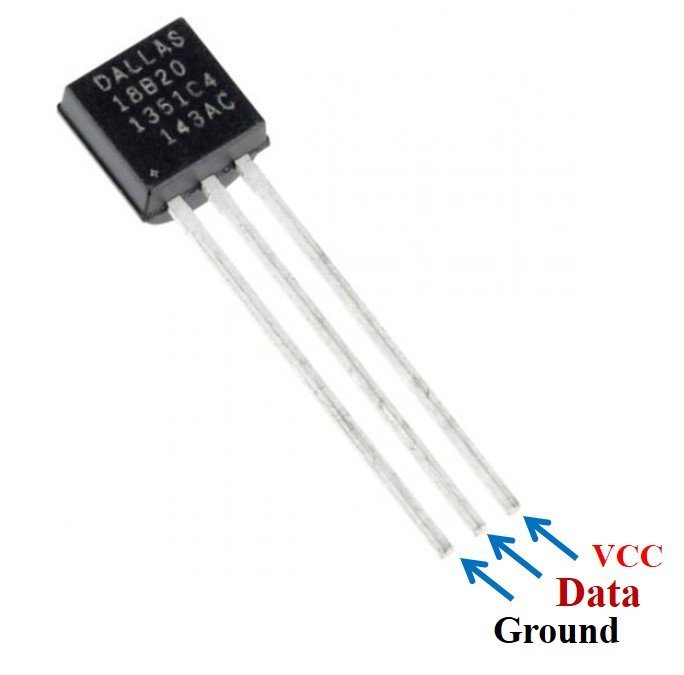
The following diagram shows the pinout of normal DS18B20 temperature sensor.
The table below lists the pin configurations:
| Pin | Description |
|---|---|
| VCC | This is the pin that powers up the sensor. 3.3V for Raspberry Pi Pico boards |
| Data | This pin gives the temperature value |
| Ground | This pin is connected to ground |
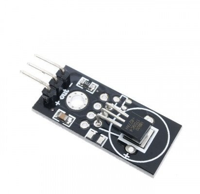
This temperature sensor also comes in a single package module which contains a sensor and a pull-up resistor. If you are using a module, you do not need to connect an external 4.7K ohm resistor. Because the module already has an onboard pull-up resistor.
DS18B20 Parasite vs Normal Mode
The DS18B20 sensor can be powered in two different modes.
Normal Mode: The sensor is powered through an external source through the VDD pin and 4.7K ohm pull-up resistor.
Parasite Mode: The sensor obtains the power from its own data line. Hence, no external power supply is required.
Interfacing Raspberry Pi Pico with DS18B20 and ESP-01
This section shows how to connect Raspberry Pi Pico with DS18B20 sensor and ESP-01.
We will require the following components:
- Raspberry Pi Pico
- DS18B20 Sensor
- 4.7k ohm resistor
- ESP-01 Module
- Connecting Wires
- Breadboard
Raspberry Pi Pico with DS18B20
We will power the DS10B20 sensor in normal mode. Therefore its VCC pin will be connected with the 3.3V pin of Raspberry Pi Pico board through a 4.7k ohm resistor.
The DS18B20 sensor has three terminals which we saw above in the pinout. The first terminal is grounded with the Raspberry Pi Pico board. The data line of the sensor, which is the middle terminal, is connected through GP16 through a pull-up resistor of 4.7k-ohm. We can choose any other GPIO pin as well. The third terminal is powered by 3.3V from the Raspberry Pi Pico.
| Raspberry Pi Pico | DS18B20 |
|---|---|
| GND | GND |
| GP16 | Data |
| 3.3V | VCC |
You may also like to read:
You can use any other GPIO pin of Raspberry Pi Pico to connect with the data pin as well. You can refer to this post to know more about Raspberry Pi Pico GPIO pins:
Raspberry Pi Pico with ESP-01
The ESP-01 module consists of 8 pins. However, we will use 5 pins to connect with the Pi Pico board. These include the VCC, EN, GND, RX, and TX pins. RX and TX pins of the module will be connected with the UART pins of the Pi Pico board. Let us first have a look at the Raspberry Pi Pi UART Pins.
Raspberry Pi Pico UART Pins
Raspberry Pi Pico contains two identical UART peripherals with separate 32×8 Tx and 32×12 Rx FIFOs.

The following table lists the GPIO pins for both UART peripherals which are exposed on Raspberry Pi Pico development board pinouts.
| UART Pins | GPIO Pins |
|---|---|
| UART0-TX | GP0/GP12/GP16 |
| UART0-RX | GP1/GP13/GP17 |
| UART1-TX | GP4/GP8 |
| UART1-RX | GP5/GP9 |
For this guide, we will use UART0-TX and RX pins.
Follow the connection diagram below to connect the two devices.
| Raspberry Pi Pico | ESP-01 |
|---|---|
| 3.3V | VCC |
| 3.3V | EN |
| GND | GND |
| GP1 (UART0 RX) | TX |
| GP0 (UART0 TX) | RX |
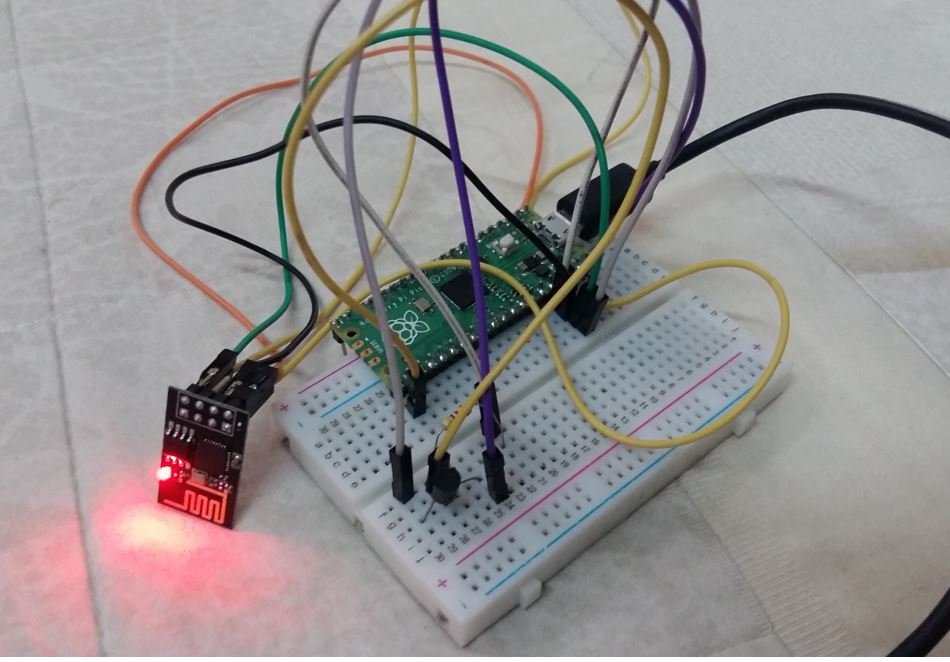
Connection Diagram Raspberry Pi Pico with DS18B20 and ESP-01
We have used the same connections as given in the two tables above. All three devices will be commonly grounded and will be powered with the same 3.3V pin of Raspberry Pi Pico.
The diagram below shows the connection diagram of Raspberry Pi Pico with DS18B20 and ESP-01.

You may like to read:
Installing DS18B20 Libraries
For this project, we will require two libraries: ds18x20.py and onewire.py. Copy both of these libraries and save them in your Raspberry Pi Pico with the respective file names. Open a new file in Thonny. Copy the libraries given below. Save them to Raspberry Pi Pico with names ds18x20.py and onewire.py under the lib folder.
ds18x20.py
# DS18x20 temperature sensor driver for MicroPython.
# MIT license; Copyright (c) 2016 Damien P. George

from micropython import const

_CONVERT = const(0x44)
_RD_SCRATCH = const(0xBE)
_WR_SCRATCH = const(0x4E)


class DS18X20:
    def __init__(self, onewire):
        self.ow = onewire
        self.buf = bytearray(9)

    def scan(self):
        return [rom for rom in self.ow.scan() if rom[0] in (0x10, 0x22, 0x28)]

    def convert_temp(self):
        self.ow.reset(True)
        self.ow.writebyte(self.ow.SKIP_ROM)
        self.ow.writebyte(_CONVERT)

    def read_scratch(self, rom):
        self.ow.reset(True)
        self.ow.select_rom(rom)
        self.ow.writebyte(_RD_SCRATCH)
        self.ow.readinto(self.buf)
        if self.ow.crc8(self.buf):
            raise Exception("CRC error")
        return self.buf

    def write_scratch(self, rom, buf):
        self.ow.reset(True)
        self.ow.select_rom(rom)
        self.ow.writebyte(_WR_SCRATCH)
        self.ow.write(buf)

    def read_temp(self, rom):
        buf = self.read_scratch(rom)
        if rom[0] == 0x10:
            if buf[1]:
                t = buf[0] >> 1 | 0x80
                t = -((~t + 1) & 0xFF)
            else:
                t = buf[0] >> 1
            return t - 0.25 + (buf[7] - buf[6]) / buf[7]
        else:
            t = buf[1] << 8 | buf[0]
            if t & 0x8000:  # sign bit set
                t = -((t ^ 0xFFFF) + 1)
            return t / 16
onewire.py
# 1-Wire driver for MicroPython
# MIT license; Copyright (c) 2016 Damien P. George

import _onewire as _ow


class OneWireError(Exception):
    pass


class OneWire:
    SEARCH_ROM = 0xF0
    MATCH_ROM = 0x55
    SKIP_ROM = 0xCC

    def __init__(self, pin):
        self.pin = pin
        self.pin.init(pin.OPEN_DRAIN, pin.PULL_UP)

    def reset(self, required=False):
        reset = _ow.reset(self.pin)
        if required and not reset:
            raise OneWireError
        return reset

    def readbit(self):
        return _ow.readbit(self.pin)

    def readbyte(self):
        return _ow.readbyte(self.pin)

    def readinto(self, buf):
        for i in range(len(buf)):
            buf[i] = _ow.readbyte(self.pin)

    def writebit(self, value):
        return _ow.writebit(self.pin, value)

    def writebyte(self, value):
        return _ow.writebyte(self.pin, value)

    def write(self, buf):
        for b in buf:
            _ow.writebyte(self.pin, b)

    def select_rom(self, rom):
        self.reset()
        self.writebyte(self.MATCH_ROM)
        self.write(rom)

    def scan(self):
        devices = []
        diff = 65
        rom = False
        for i in range(0xFF):
            rom, diff = self._search_rom(rom, diff)
            if rom:
                devices += [rom]
            if diff == 0:
                break
        return devices

    def _search_rom(self, l_rom, diff):
        if not self.reset():
            return None, 0
        self.writebyte(self.SEARCH_ROM)
        if not l_rom:
            l_rom = bytearray(8)
        rom = bytearray(8)
        next_diff = 0
        i = 64
        for byte in range(8):
            r_b = 0
            for bit in range(8):
                b = self.readbit()
                if self.readbit():
                    if b:  # there are no devices or there is an error on the bus
                        return None, 0
                else:
                    if not b:  # collision, two devices with different bit meaning
                        if diff > i or ((l_rom[byte] & (1 << bit)) and diff != i):
                            b = 1
                            next_diff = i
                self.writebit(b)
                if b:
                    r_b |= 1 << bit
                i -= 1
            rom[byte] = r_b
        return rom, next_diff

    def crc8(self, data):
        return _ow.crc8(data)
Getting ThingSpeak API Ready
ThingSpeak is an open-source API that is used to store or retrieve data using HTTP or MQTT protocol. This takes place over the Internet or through the LAN. We will use this API to publish sensor readings from DS18B20 integrated with our Raspberry Pi Pico board. In ThingSpeak you can access your data from anywhere in the world. You can display your data in plots and graphs.
For more information about ThingSpeak API, you can have a look at our previous ESP32/ESP8266 tutorials given below:
- ESP8266 Wi-Fi Module interfacing with Arduino: Send data to server (ThingSpeak)
- ESP32 HTTP POST using Arduino IDE (ThingSpeak and IFTTT)
- HTTP GET using ESP32 and Arduino IDE (OpenWeatherMap.org and ThingSpeak)
Creating Account
ThingSpeak API is free to use but we will have to create a MathWorks Account.
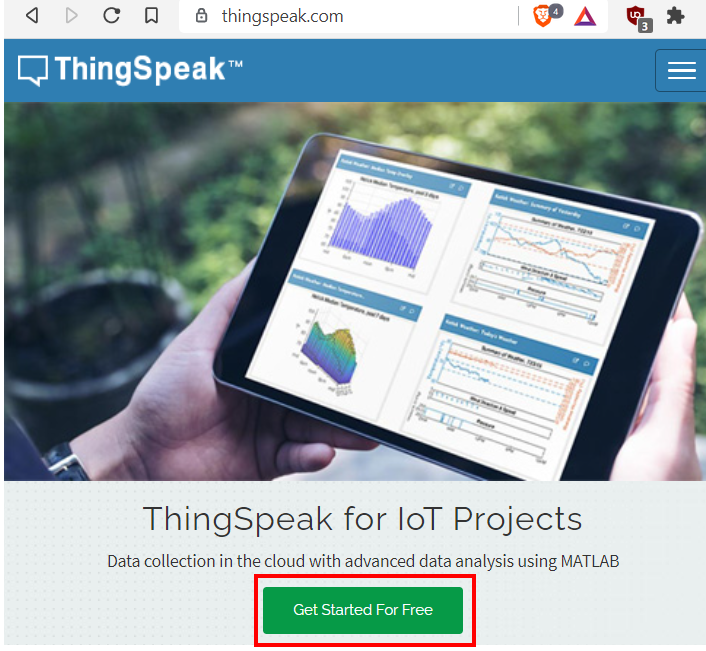
First go to the following website: https://thingspeak.com/
The following window will appear. Click on the ‘Get Started for Free’ button.
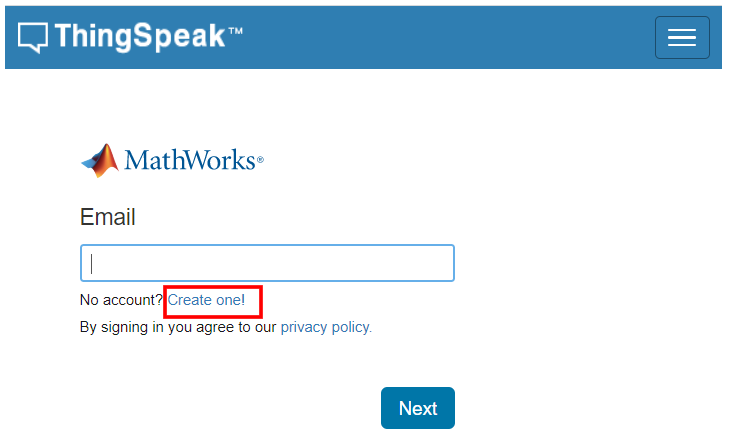
Now you will be redirected to the account window. If you already have an existing MathWorks account you can use that to log in. Otherwise, you will have to create a new one. Click ‘Create One!’ to make a new MathWorks account.
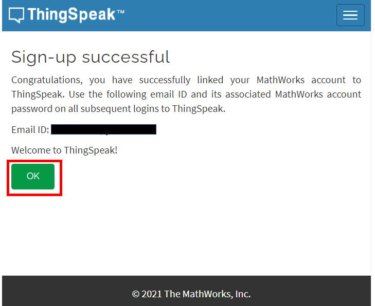
When you have successfully signed in you will receive the following notification:
Click ‘OK’.
Publish to single field of sensor readings to ThingSpeak (Temperature)
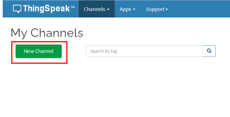
We will start by creating a new channel for our project. Go to Channels > My Channels. Then click ‘New Channel’.
You will be prompted to give a name to your channel. We will give a name, some description and mark the first field. In this section, we will show you how to publish to a single field. You can use any name, description, and field according to your preference. There are a total of eight fields that we can add to our channel at the same time. We will tick the first field and add the name. Click ‘Save Channel’ to proceed.

Your channel will now be created.

Go to private view and click the pencil icon on top of the Field Chart. This will let us customize the graph according to our preference. You can add details accordingly. After you press the Save button, the chart will get updated to the settings you just set.

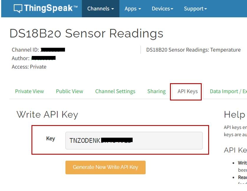
After that go to the API key tab and click it. You will now be able to access your unique write API key. Save it and keep it secure as you will need it later in the program code.
Raspberry Pi Pico & ESP-01 ThingSpeak MicroPython Sketch (DS18B20)
Open your Thonny IDE and go to File > New to open a new file. Copy the code given below in that file. You just have to replace the network credentials and your ThingSpeak API key.
import uos
import machine, onewire, ds18x20
import utime
from machine import Pin


myHOST = 'api.thingspeak.com'
myPORT = '80'
myAPI = '****************'

print()
print("Machine: \t" + uos.uname()[4])
print("MicroPython: \t" + uos.uname()[3])

ds_pin = machine.Pin(16)
ds_sensor = ds18x20.DS18X20(onewire.OneWire(ds_pin))
roms = ds_sensor.scan()

uart0 = machine.UART(0, baudrate=115200)
print(uart0)

def Rx_ESP_Data():
    recv=bytes()
    while uart0.any()>0:
        recv+=uart0.read(1)
    res=recv.decode('utf-8')
    return res
def Connect_WiFi(cmd, uart=uart0, timeout=3000):
    print("CMD: " + cmd)
    uart.write(cmd)
    utime.sleep(7.0)
    Wait_ESP_Rsp(uart, timeout)
    print()

def Send_AT_Cmd(cmd, uart=uart0, timeout=3000):
    print("CMD: " + cmd)
    uart.write(cmd)
    Wait_ESP_Rsp(uart, timeout)
    print()

def Wait_ESP_Rsp(uart=uart0, timeout=3000):
    prvMills = utime.ticks_ms()
    resp = b""
    while (utime.ticks_ms()-prvMills)<timeout:
        if uart.any():
            resp = b"".join([resp, uart.read(1)])
    print("resp:")
    try:
        print(resp.decode())
    except UnicodeError:
        print(resp)

Send_AT_Cmd('AT\r\n')          #Test AT startup
Send_AT_Cmd('AT+GMR\r\n')      #Check version information
Send_AT_Cmd('AT+CIPSERVER=0\r\n')      #Check version information
Send_AT_Cmd('AT+RST\r\n')      #Check version information
Send_AT_Cmd('AT+RESTORE\r\n')  #Restore Factory Default Settings
Send_AT_Cmd('AT+CWMODE?\r\n')  #Query the Wi-Fi mode
Send_AT_Cmd('AT+CWMODE=1\r\n') #Set the Wi-Fi mode = Station mode
Send_AT_Cmd('AT+CWMODE?\r\n')  #Query the Wi-Fi mode again
Connect_WiFi('AT+CWJAP="A1601","123456789104"\r\n', timeout=5000) #Connect to AP
Send_AT_Cmd('AT+CIFSR\r\n',timeout=5000)    #Obtain the Local IP Address
Send_AT_Cmd('AT+CIPMUX=1\r\n')    #Obtain the Local IP Address
utime.sleep(1.0)
print ('Starting connection to ESP8266...')
while True:
    print('Found DS devices')
    print('Temperature')
    ds_sensor.convert_temp()
    utime.sleep(1)
    for rom in roms:
      temperature_Celsius = round(ds_sensor.read_temp(rom), 2)
      print(temperature_Celsius)
    utime.sleep(3)

    print ('!About to send data to thingspeak')
    sendData = 'GET /update?api_key='+ myAPI +'&field1='+str(temperature_Celsius)
    Send_AT_Cmd('AT+CIPSTART=0,\"TCP\",\"'+ myHOST +'\",'+ myPORT+'\r\n')
    utime.sleep(1.0)
    Send_AT_Cmd('AT+CIPSEND=0,' +str(len(sendData)+4) +'\r\n')
    utime.sleep(1.0)
    Send_AT_Cmd(sendData +'\r\n')
    utime.sleep(4.0)
    Send_AT_Cmd('AT+CIPCLOSE=0'+'\r\n') # once file sent, close connection
    utime.sleep(4.0)
    print ('Data send to thing speak')
How the Code Works?
We will start by importing the machine module and the uos module. We will also import the Pin class from the machine module. This is because we have to specify the GPIO pin connected with the data pin of DS18B20 sensor. We also import the utime module so that we will be able to add a delay in between our readings. Also, import one wire and ds18x20 libraries that we just uploaded to our board.
import uos
import machine, onewire, ds18x20
import utime
from machine import Pin
Then, we will print the information about our current operating system in the Thonny shell terminal. We will uos.uname() and print the operating system version and release.
print()
print("Machine: \t" + uos.uname()[4])
print("MicroPython: \t" + uos.uname()[3])
Next, we will create an instance of Pin class with an object name of ds_pin and set GP16 as the DS18B20 data line pin. The scan() method scans all DS18B20 sensors connected to the ds_sensor pin and saves the 64-bit address of each sensor in a list variable that is “roms”. Later, we will use these addresses to read temperature from the sensor one by one.
ds_pin = machine.Pin(16)
ds_sensor = ds18x20.DS18X20(onewire.OneWire(ds_pin))
roms = ds_sensor.scan()
Initialize UART Communication
Then we will create an uart object by using UART() and specify the UART channel as the first parameter and the baud rate as the second parameter. We are using UART0 in this case with baud rate 115200 for the uart communication. ESP8266 has a default baud rate of 115200 hence we will use the same baud rate here for Raspberry Pi Pico UART communication in order to create synchronization. Moreover we will also print the UART details in the shell terminal.
uart0 = machine.UART(0, baudrate=115200)
print(uart0)
Also, include the ThingSpeak host, port and write API key to successfully publish readings to the API. Make sure to replace your API key in the place specified by ‘****************’
myHOST = 'api.thingspeak.com'
myPORT = '80'
myAPI = '****************'
This Connect_WiFi() function is used to connect ESP8266 with WiFi.
def Connect_WiFi(cmd, uart=uart0, timeout=3000):
    print("CMD: " + cmd)
    uart.write(cmd)
    utime.sleep(7.0)
    Wait_ESP_Rsp(uart, timeout)
    print()
Next, we will define three functions. The first one is Rx_ESP_Data(). This reads the serial data being received. This data is decoded from UTF-8 format and returned.
def Rx_ESP_Data():
    recv=bytes()
    while uart0.any()>0:
        recv+=uart0.read(1)
    res=recv.decode('utf-8')
    return res
The second function is Send_AT_Cmd(cmd, uart=uart0, timeout=3000). It takes in three parameters, the AT command, the UART channel and the response time. This function will be used to it send an AT command to ESP8266 via uart0. The response time is set to 3 seconds.
def Send_AT_Cmd(cmd, uart=uart0, timeout=3000):
    print("CMD: " + cmd)
    uart.write(cmd)
    Wait_ESP_Rsp(uart, timeout)
    print()
The Wait_ESP_Rsp(uart=uart0, timeout=3000) function waits for 3 seconds to get the response from ESP8266. After receiving the data from ESP8266 it concatenates the received bytes and prints them on the shell terminal.
def Wait_ESP_Rsp(uart=uart0, timeout=3000):
    prvMills = utime.ticks_ms()
    resp = b""
    while (utime.ticks_ms()-prvMills)<timeout:
        if uart.any():
            resp = b"".join([resp, uart.read(1)])
    print("resp:")
    try:
        print(resp.decode())
    except UnicodeError:
        print(resp)
AT Commands
Now let us look at the series of AT commands that we will send through UART0 to ESP8266.
Send_AT_Cmd('AT\r\n')          #Test AT startup
Send_AT_Cmd('AT+GMR\r\n')      #Check version information
Send_AT_Cmd('AT+CIPSERVER=0\r\n')      #Check version information
Send_AT_Cmd('AT+RST\r\n')      #Check version information
Send_AT_Cmd('AT+RESTORE\r\n')  #Restore Factory Default Settings
Send_AT_Cmd('AT+CWMODE?\r\n')  #Query the Wi-Fi mode
Send_AT_Cmd('AT+CWMODE=1\r\n') #Set the Wi-Fi mode = Station mode
Send_AT_Cmd('AT+CWMODE?\r\n')  #Query the Wi-Fi mode again
Connect_WiFi('AT+CWJAP="YOUR_SSID","YOUR_PASSWORD"\r\n', timeout=5000) #Connect to AP
Send_AT_Cmd('AT+CIFSR\r\n',timeout=5000)    #Obtain the Local IP Address
Send_AT_Cmd('AT+CIPMUX=1\r\n')    #Obtain the Local IP Address
utime.sleep(1.0)
Send_AT_Cmd('AT+CIPSERVER=1,80\r\n')    #Obtain the Local IP Address
utime.sleep(1.0)AT: This type of command is used to test the startup function of WiFi module. The response would be ok, against this command if everything is ok.
Send_AT_Cmd('AT\r\n') #Test AT startupAT+GMR : This type of AT command is used to check the version of AT command and we used SDK version of AT command in this type of WIFI module.
Send_AT_Cmd('AT+GMR\r\n') #Check version informationAT+CIPSERVER=0: This configures the ESP8266 as server and sets the mode as 0 which means delete server (need to follow by restart)
Send_AT_Cmd('AT+CIPSERVER=0\r\n') AT+RST: This type of command is used for reset the WiFi module when it is in working condition. The response would be ok, when reset the module.
Send_AT_Cmd('AT+RST\r\n') AT+RESTORE: This type of command is used to restore factory settings means, when this command is entered then all the parameters are reset automatically to default one’s.
Send_AT_Cmd('AT+RESTORE\r\n') #Restore Factory Default SettingsAT+CWMODE? : This type of command is used to query the WiFi mode of ESP8266.
Send_AT_Cmd('AT+CWMODE?\r\n') #Query the WiFi modeAT+CWMODE=1 : This sets the WiFi mode of ESP8266 in this case in station mode.
Send_AT_Cmd('AT+CWMODE=1\r\n') #Set the WiFi mode = Station modeAT+CWJAP=”SSID”,”PASSWORD”\r\n’, timeout=TIME_ms : This connects the ESP8266 with an AP whose SSID and password are given, The timeout here is the reconnection time.
Connect_WiFi('AT+CWJAP="YOUR_SSID","YOUR_PASSWORD"\r\n', timeout=5000) #Connect to APAT+CIFSR: This command obtains the local IP address.
Send_AT_Cmd('AT+CIFSR\r\n')AT+CIPMUX=1:This command is used to enable multiple connections (maximum 4)
Send_AT_Cmd('AT+CIPMUX=1\r\n')AT+CIPSERVER=1: This command configures ESP8266 as server.
Send_AT_Cmd('AT+CIPSERVER=1,80\r\n')Get DS18B20 Sensor Readings and Publish to ThingSpeak
Inside the while loop we will first get the sensor readings. We will call the object(ds_sensor) on convert_temp() method before reading the temperature from the sensor using its unique address. To read the temperature in Celsius, we use the read_temp() procedure on the ds_sensor object and pass an address stored in the roms list. The DS18B20 temperature sensor provides data output in float data type. We will round off the reading to 2 decimal places and print it in the Thonny shell terminal.
while True:
    print('Found DS devices')
    print('Temperature')
    ds_sensor.convert_temp()
    utime.sleep(1)
    for rom in roms:
      temperature_Celsius = round(ds_sensor.read_temp(rom), 2)
      print(temperature_Celsius)
    utime.sleep(3)
Finally, we will send these sensor readings to ThingSpeak dashboard.
print ('!About to send data to thingspeak')
    sendData = 'GET /update?api_key='+ myAPI +'&field1='+str(temperature_Celsius)
    Send_AT_Cmd('AT+CIPSTART=0,\"TCP\",\"'+ myHOST +'\",'+ myPORT+'\r\n')
    utime.sleep(1.0)
    Send_AT_Cmd('AT+CIPSEND=0,' +str(len(sendData)+4) +'\r\n')
    utime.sleep(1.0)
    Send_AT_Cmd(sendData +'\r\n')
    utime.sleep(4.0)
    Send_AT_Cmd('AT+CIPCLOSE=0'+'\r\n') # once file sent, close connection
    utime.sleep(4.0)
    print ('Data send to thing speak')
We will create a variable ‘sendData’ that contains a GET request that we will make to ThingSpeak to udate the respective field with the values held in the variable ‘temperature_Celsius’ converted to a string.
sendData = 'GET /update?api_key='+ myAPI +'&field1='+str(temperature_Celsius)First, we are writing the AT command: AT+CIPSTART=0,\”TCP\”,\”‘+ myHOST +’\”,’+ myPORT+’\r\n’ This command is used to set the port connection and address of port.
Next after a delay of 1 second, we send the AT command: AT+CIPSEND=’ID’, ‘LENGTH’ This will set the length of the data that will be sent. It tells the WI-FI module how many bytes we want to send to the server.
Then we send the data to ThingSpeak via to be pusblished to their respective fields.
After that, we will close the multiple connections as we are sending the AT command: AT+CIPCLOSE=’ID’.
    Send_AT_Cmd('AT+CIPSTART=0,\"TCP\",\"'+ myHOST +'\",'+ myPORT+'\r\n')
    utime.sleep(1.0)
    Send_AT_Cmd('AT+CIPSEND=0,' +str(len(sendData)+4) +'\r\n')
    utime.sleep(1.0)
    Send_AT_Cmd(sendData +'\r\n')
    utime.sleep(4.0)
    Send_AT_Cmd('AT+CIPCLOSE=0'+'\r\n') # once file sent, close connection
    utime.sleep(4.0)
    print ('Data send to thing speak')
Demonstration
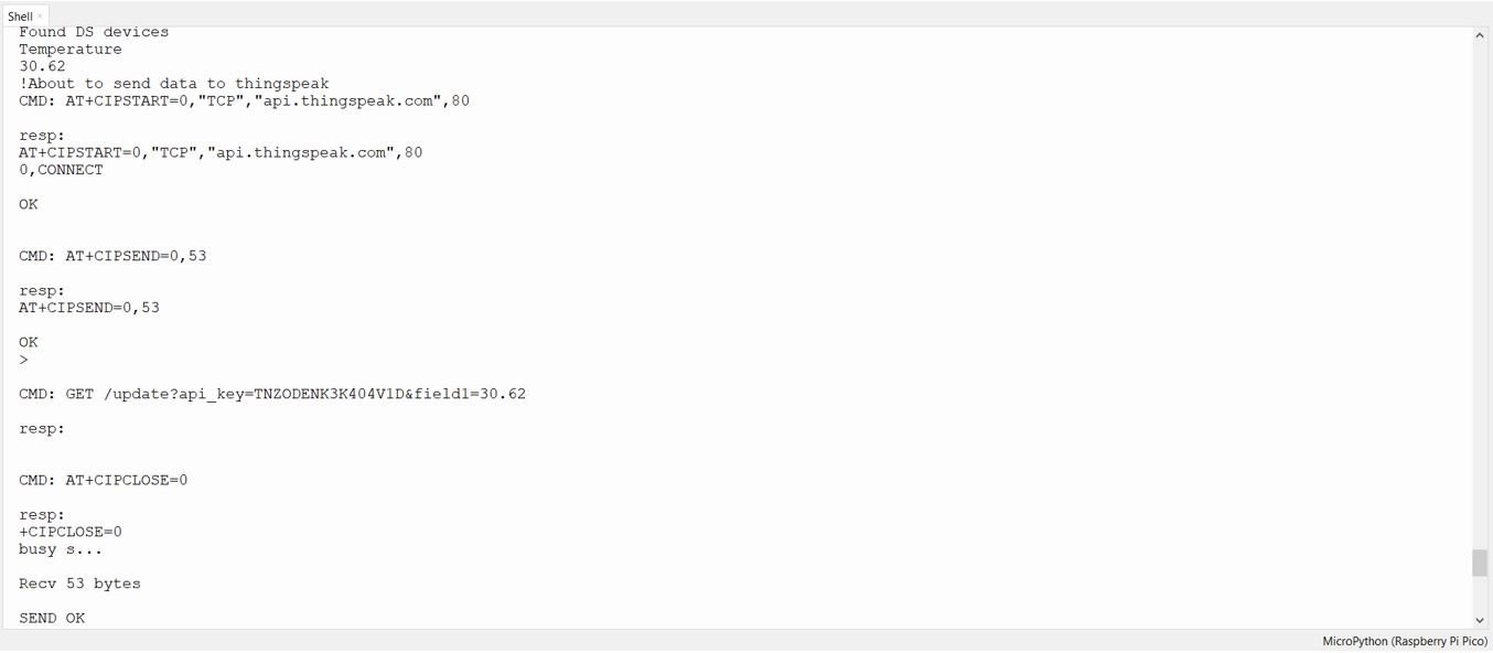
After you have uploaded your code to Raspberry Pi Pico board head over to the shell terminal. In the Thonny shell terminal you will be able to view the board getting connected. After every few seconds, new sensor readings will keep appearing as they get published to their respective fields.
Next, open the ThingSpeak API and you will be able to see temperature readings updating in your chart.

Watch the demonstration below to have a better insight:
Conclusion
In conclusion, we were able to learn how to publish DS18B20 sensor readings to ThingSpeak using MicroPython and Raspberry Pi Pico using ESP-01 Wi-Fi module in a fairly easy way. Likewise, you can publish single or multiple data to ThingSpeak API which you will be able to access from anywhere around the world.
You may like to read our articles on web servers with Raspberry Pi Pico:
- Raspberry Pi Pico Web Server Control GPIO Outputs
- Raspberry Pi Pico DHT22 Web Server (Weather Station)
- Raspberry Pi Pico DS18B20 Web Server (Weather Station)
- Raspberry Pi Pico BME680 Web Server with MicroPython
- Raspberry Pi Pico Web Server with BME280 (Weather Station)
Related DS18B20 tutorials and projects:
- ESP8266 NodeMCU DS18B20 Web Server with Arduino IDE
- ESP32 DS18B20 Temperature Sensor Web Server with Arduino IDE
- MicroPython: DS18B20 Web Server with ESP32/ESP8266(Weather Station)
- Single and Multiple DS18B20 with ESP32: Display Readings on OLED
- DS18B20 with ESP8266 NodeMCU (Single/Multiple): Display Readings on OLED
Thanks. Very well explained. Still new to Python never mind micropython. How do I add 2 DS18B20 sensors?
In python I call up each one separately?
I will check and comeback to you.
Each DS18B20 has a unique 64-bit address assigned to it to differentiate them from one another. First, You need to find that address to label each sensor accordingly. The address can then be used to read each sensor individually using their addresses.
Hi, Yes they do and in python you do it like this
base_dir = ‘/sys/bus/w1/devices/’
device_folder = glob.glob(base_dir + ’28-3c01xxxxxx3fd’)[0]
device_file = device_folder + ‘/w1_slave’
Where as in pico, where do you put it?
class DS18X20:
def __init__(self, onewire):
self.ow = onewire
self.buf = bytearray(9)
def scan(self):
return [rom for rom in self.ow.scan() if rom[0] in (0x10, 0x22, 0x28)]
def convert_temp(self):
self.ow.reset(True)
self.ow.writebyte(self.ow.SKIP_ROM)
self.ow.writebyte(_CONVERT)
def read_scratch(self, rom):
self.ow.reset(True)
self.ow.select_rom(rom)
self.ow.writebyte(_RD_SCRATCH)
self.ow.readinto(self.buf)
if self.ow.crc8(self.buf):
raise Exception(“CRC error”)
return self.buf
def write_scratch(self, rom, buf):
self.ow.reset(True)
self.ow.select_rom(rom)
self.ow.writebyte(_WR_SCRATCH)
self.ow.write(buf)
Please check this, it might help:
https://docs.micropython.org/en/latest/library/machine.I2C.html#machine-softi2c
Hi, thanks, checked it out and am no closer. There are so few examples with pico and it makes learning a new language that much more difficult.