Arduino MKR1000 is one of the smart boards, which was designed by the combination of Arduino and wifi board. The basic purpose of designing was to introduce a small and compatible device to the market for IoT projects. IoT has been growing recently very vastly into the world and MKR1000 is one the best option due to its multiple pins and their functionality. MKR1000 was designed with SAMD21 Cortex and a low power WINC1500 WiFi board. Every IoT function can be done by using it. The larger no of pins and its features makes it more preferable as compare to the other IoT boards.
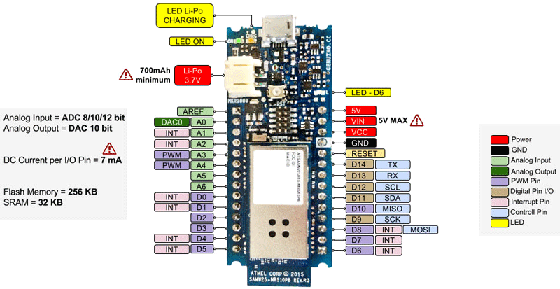
Pinout Diagram Arduino MKR1000
MKR1000 offers large numbers of GPIO pins as compared to the others and all of them are discussed below. This is a pinout diagram of the Arduino MKR1000 development board.

Digital Input/Output Pins
Digital output/input has become a basic requirement for every circuit. In Arduino MKR1000, there are 15 of them and all are control able through Arduino programming. The power voltage on these pins won’t be more than 3.3V. In the case of input, the external device should only use 3.3V maximum. A few increases in voltage from 3.3V can damage the whole board.
Some I/O pins can perform some other functions besides simple input/output. So before using them, they should be initialized with the program about their use. All pins are unable to perform multiple functions at the same time and the initialized program can only be changed through programming. All I/O pins for the digital signal are:
- D0 – GPIO0
- D1 – GPIO1
- D2 – GPIO2
- D3 – GPIO3
- D4 – GPIO4
- D5 – GPIO5
- D6 – GPIO6
- D7 – GPIO7
- D8 – GPIO8
- D9 – GPIO9
- D10 – GPIO10
- D11 – GPIO11
- D12 – GPIO12
- D13 – GPIO13
- D14 – GPIO14
D6 pin is connected with an onboard LED. Any pulse on the LED will affect the LED too.
Interrupt Pins
In IoT interrupt is one of the basic requirements to perform some operations like high voltage controlling etc. and interfacing with some smart sensors. Arduino MKR1000 has a total of 9 interrupt pins. The interrupt is basically to get the attention of the CPU. During using any interrupt two things should be kept in mind.
First, there should not be any delay within the interrupt function and second, there should not be any serial print data within the interrupt function. All interrupt pins can operate according to the input signal. Usually, Arduino operates on three types of interrupt signals: Rising Edge, Chane within the wave, Falling edge. All interrupt pins of Arduino MKR1000 board are:
- INT0 – GPIO0
- INT1 – GPIO1
- INT4 – GPIO4
- INT5 – GPIO5
- INT6 – GPIO6
- INT7 – GPIO7
- INT8 – GPIO8
- INT16 – GPIO9
- INT17 – GPIO1
Arduino MKR1000 WiFi Board Serial Communication Channels
Most of the devices use serial communication method and serial communication also have multiple types. Those which are present in the Arduino MKR1000 are:
USART Pins
All Arduino boards offer the USART serial communication through USB input port but they also have pins for that. In Arduino MKR1000 there are one USART communication pins. Those pins are two in number and use the internal program as a clock. It is known as the baud rate. The baud rate has different specific values that can be initialized through programming to communicate with two devices. The USART pins on Arduino MKR1000 wifi board are:
- RX1 – GPIO13
- TX1 – GPIO14
SPI Pins
SPI is protocol is also for serial communication. In this communication device uses four-wire for communication. Those wires are MOSI, MISO, SCK, SS’. MOSI pin is used to send the data from Arduino to the external module.
MISO is used in Arduino to receive the transmitted data. SCK is for clock pulse, to keep the data transmission according to the external clock. The last pin is a slave select pin which is just for selecting the different devices. The slave select pin is most efficient in the case of multiple SPI devices. Any I/O can be made slave select pin through programming. All SPI pins are Arduino MKR1000 Board are:
- MISO – GPIO10
- MOSI – GPIO8
- SCK – GPIO9
I2C Pins
I2C is also one of the popular serial communication. It uses two wires only, one for data and one for the clock. This method is only used for most of the time as one-way serial communication. In Arduino MKR1000 all I2C pins are:
- SDA – GPIO11
- SCL – GPIO12
MKR1000 WiFi Board PWM Pins
Arduino MKR1000 has multiple PWM pins. It has a total of 12 PWM and they can generate any desired output signal. All PWM can be controlled able through programming. All the PWM pins have the value from 0 to 255. Each output signal can be converted to the desired output signal through only PWM pins. All PWM are:
- PWM0 – GPIO0
- PWM1 – GPIO1
- PWM2 – GPIO2
- PWM3 – GPIO3
- PWM4 – GPIO4
- PWM5 – GPIO5
- PWM6 – GPIO6
- PWM7 – GPIO7
- PWM8 – GPIO8
- PWM10 – GPIO10
- PWM18 – GPIO18
- PWM19 – GPIO19
Arduino MKR1000 Analog to Digital Converter Channels
All analog and digital pins can convert any analog input data to digital data. In Arduino MKR1000 the ADC is different from others. It has three ADC 8bit, 10 bits, and 12bits ADC. These ADC takes the analog signal as the voltage from 7 ADC pins and then convert them. All ADC pins of Arduino MKR1000 are:
- ADC0 – GPIO15
- ADC1 – GPIO16
- ADC2 – GPIO17
- ADC3 – GPIO18
- ADC4 – GPIO19
- ADC5 – GPIO20
- ADC6 – GPIO21
- ADC7 – GPIO22
AREF Pin
At default, analog input pins use the power supply voltage as a reference. Due to power supply and analog output device voltages, sometimes the ADC gave unexpected values. To solve this issue Arduino MKR1000 has an analog reference. This pin can be used to give the voltage of the analog output device voltage as a reference.
DAC Modules
Most of the time only analog to digital pins are required but some time to operate external devices analog signal is required. In these cases, Arduino MKR1000 has a DAC pin. This pin can be used through programming but the voltages on this pin voltage won’t be increased more than the power supply voltages.
Reset Pin
Arduino MKR1000 can be reset through the internal program but it also has an external reset pin. The external reset pin can be used by any external module to give the LOW pulse to reset the device.
Power Pins in Arduino MKR1000
These are multiple power input and output pins in MKR1000.
Lip-Po Pin
Li-po pin is one of the power input pins of the MKR1000. It can only hold up to 3.7V more than 3.7 volts can damage the board. The current value can also be effective on the board too. To keep the board safe the current also should not be more than 7000mAh. It is mostly by a single Li-Po cell
USB Power
The USB port mostly connects to the computer or chargers which gives 4.7 to 5V. In the case of increasing using any supply just make sure the voltage should not increase more than 5V.
Vin
There is a power input pin on the Arduino board which can be used for power input. The input power on the Vin pin should be only 5-6V.
5V
The 5V pin used to get the 5V for external modules. The voltage on these pins comes directly from the USB pin.
VCC
VCC is a power output pin. The power-on the VCC pin can be used as input for the device. It has a maximum of 3.3 volts which comes from the regulator.
Arduino MKR1000 Features and Specifications
| Features and Specifications | |
|---|---|
| Microcontroller | SAMD21 Cortex-M0 with 32bit low power ARM MCU |
| Power Input (USB/VIN) | 5V |
| Supported Battery | Single-cell of Li-po |
| Circuit Voltage | 3.3V |
| Digital I/O Pins | 15 Pins |
| PWM Pins | 12 Pins |
| UART | 1 Channel |
| SPI | 1 Channel |
| I2C | 1 Channel |
| Analog Input Pins | 7 Pins (8/10/12 bit) |
| Analog Output Pins | 1 Pin (DAC 10 bit) |
| External Interrupts | 8 Pins |
| DC Current per I/O Pin | 7mA |
| Oscillator | 32.768 kHz (RTC), 48 MHz |
| POWER LED | Available |
| LED BUILTIN | D6 |
| WiFi | Available |
| Lan | Not Available |
| Boot Loader | Available |
| Length | 61.5 mm |
| Width | 25 mm |
| Weight | 32 gr. |
| Flash Memory | 256 KB |
| SRAM | 32 KB |
| EEPROM | no |
Arduino MKR1000 Features and Specifications Applications
- Arduino MKR1000 is mostly used in IoT Projects.
- It can also be used to control motors, relays or any other low voltage device.
- The board gives a DAC pin that can be used for analog output and it is one of the cheapest analog output devices.
Arduino MKR1000 WiFi Board 2-D Diagram
