In this user guide, we will learn to build an RGB LED Control Android App with MIT App Inventor and control it using Arduino. This Andriod app will allow us to change the color of an RGB LED by setting it from a color picker featured on the application screen. The transmission of RGB values will be through the HC-05 Bluetooth module.
You can also check a similar guide:
- Arduino Send Sensor Readings to Android app with MIT App Inventor
- Control ESP32 over Internet using Android App with MIT App Inventor
- Arduino Send Messages from Android to LCD with MIT App Inventor
Arduino RGB LED Control using Android App Project Overview
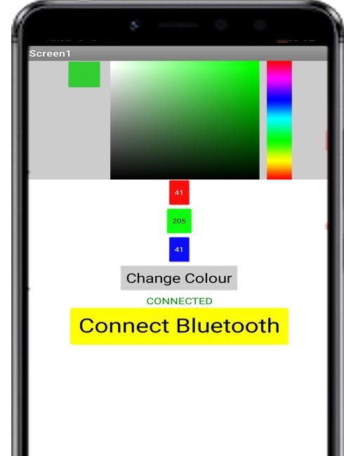
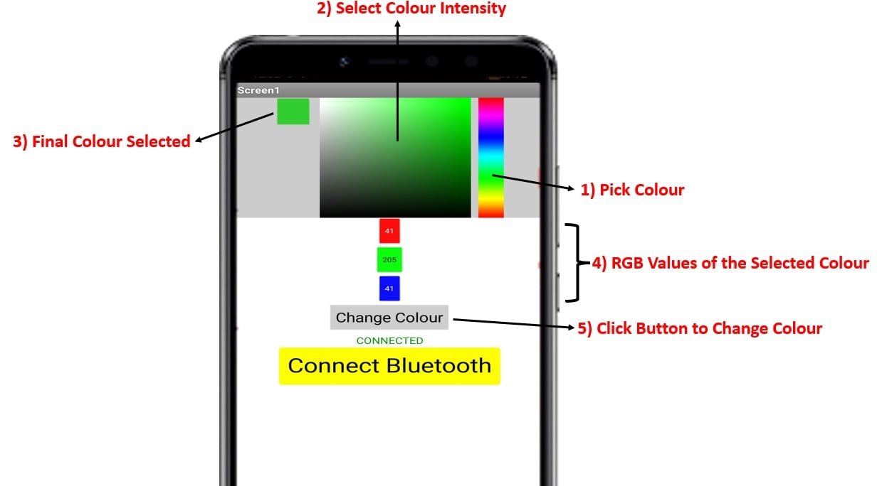
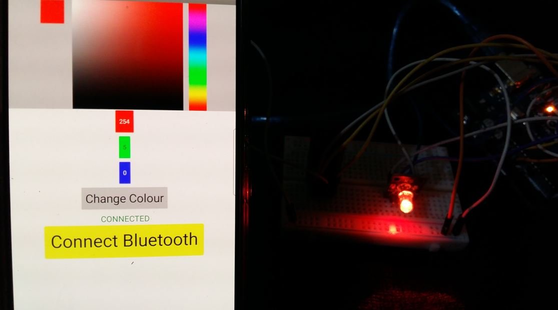
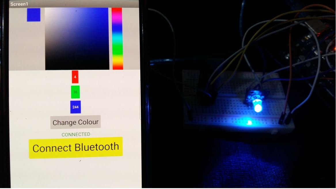
We will create an Arduino IoT app through HC-05 and MIT App Inventor to control an RGB LED. The android app features a colour picker on the right side of the screen. The user selects the colour from the colour spectrum. Next, the user selects the intensity of the colour from the middle block. The final selected colour is shown in the block at the left. Likewise, the RGB values change as the colour is selected shown by the three labels below. Below that, you can find the ‘Change Colour’ button. Pressing this button, transmits the RGB values selected to the Bluetooth module.
To enable Bluetooth connectivity, there is a button saying ‘Connect Bluetooth’ that opens a List picker which opens up Bluetooth devices currently paired with the android phone. You can select HC-05 Bluetooth module from the list. Another label saying Bluetooth is Connected or disconnected is also shown on the screen.
We aim to build an application that will control the RGM LED connected with Arduino programmed in Arduino IDE. This transmission of data from the module to the application will occur via Bluetooth.
We will require the following for our project:
Hardware Required:
- Arduino UNO
- Common cathode RGB LED
- Three 220 ohm resistors (not required if using RGB LED module)
- HC-05 Module
- Connecting Wires
- Breadboard
Software Required:
- Arduino IDE
- MIT App Inventor
- Android Smartphone with MIT AI2 Companion installed
Introducting RGB LED
RGB LED is a light-emitting diode that emits red, green, and blue lights. It consists of three discreet LEDs: red, green, and blue housed in a single packet so by combining these three colors we can create any color. Whenever voltage is applied to the red terminal, a red light will emit, and similarly when the voltage is applied to the Green and blue terminal, green and blue lights will emit respectively.
The RGB LED has four pins. These pins are used in order to control the color of the LED. The longest pin is either the anode or the cathode depending on the type of the RGB LED.
There is two types of RGB light-emitting diodes are available in the market.
- Common Anode type: In common Anode type, Anode is common for all three Light emitting diodes and Anode of all the light emitting diodes connects with positive power supply. Other terminals connects with microcontroller and we turn on and off these terminals according to which LED we want to turn on or turn off.
- Common Cathode type: In common Cathode type, Cathode of all three light emitting diodes are common and common cathode terminal is connected with ground of power supply and other terminal of each power LED is connected with pic microcontroller according to which LED we want to turn on or turn off.
Picture of both common anode and common cathode types RGB LED is shown below:

Pinout
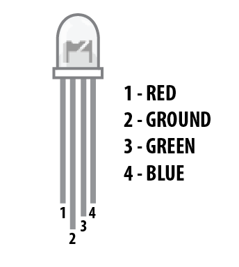
RGB LED and its pinout is shown below.
| Pin | Description |
| 1 | This is the red color select pin. Connect with digital output pin of microcontroller. |
| 2 | This is the ground pin for the common cathode type and the 5 volts Vdd pin for the common anode type. |
| 3 | This is the Blue color select pin. Connect with digital output pin of microcontroller. |
| 4 | This is the Green color select pin. Connect with digital output pin of microcontroller. |
Interfacing RGB LED and HC-05 module with Arduino board
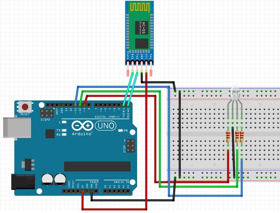
The red, green, and blue pins of the RGM LED will be connected with PWM enabled pins of Arduino. We will use D9, D10, and D11 to connect with each color pin..
Point to Note:
- In order to limit the current that will run through the RGB LED , we will need to use three resistors one for each colour pin. If we do not use a resistor or if we use a low resistor value the LED will be destroyed. We need to use a 220 ohm resistor or higher.
Follow the connections to connect HC-05 module with Arduino:
- Bluetooth Tx with Arduino UNO Rx (D0)
- Bluetooth Rx with Arduino UNO Tx (D1)
- Bluetooth VCC with Arduino UNO +5V
- Bluetooth GND with Arduino UNO GND
The schematic diagram below shows the connection between RGB LED, HC-05 and Arduino.
Additionally, the RGB LED also comes in a module with the current limiting resistors already attached. They are also available in two kinds: the common cathode module and the common anode module.
Below you can view the two modules with their pin outs.

Follow the schematic diagram below, if you are using the common cathode RGB LED module.
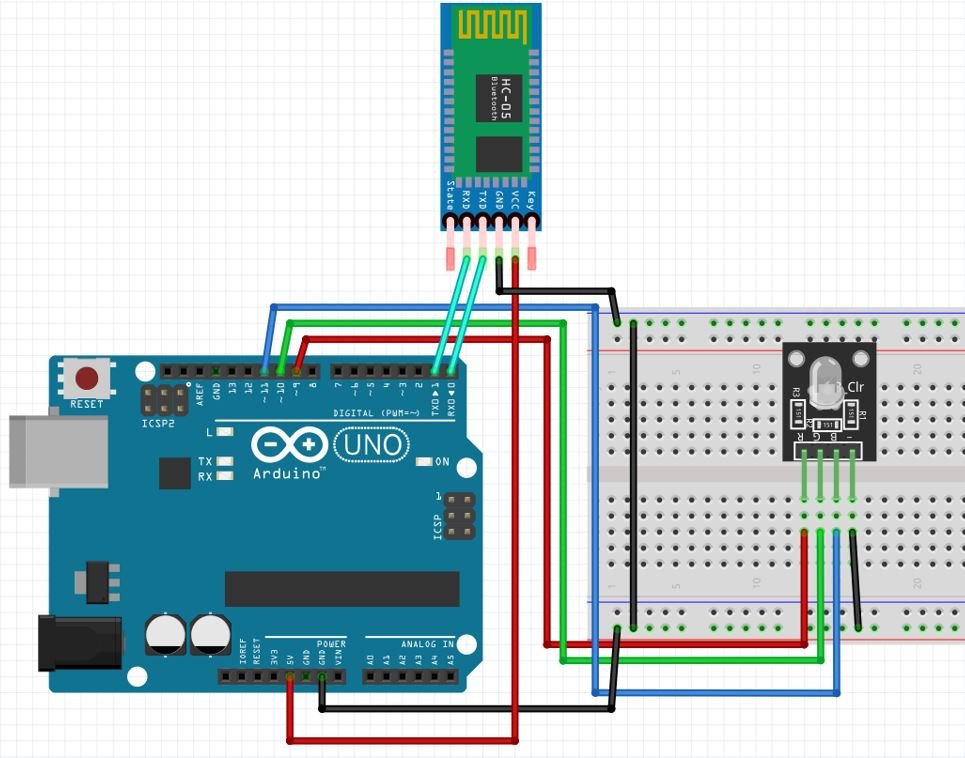
The RGM LED module already comes with the current limiting resistors so we do not to add external resistors.
We have used the RGB LED Module for this project.

NOTE: Make sure you plug out the Tx and Rx pins out of Arduino before uploading the program. After uploading the program connect them back. Otherwise, you can get an error.
You may also like to read:
Arduino Sketch RGB LED Control
Open your Arduino IDE and go to File > New to open a new file. Copy the code given below in that file.
#define MaxChar 12
char value[MaxChar];
char ReadChar;
byte index = 0;
int i;
int redPin = 9;
int greenPin = 10;
int bluePin = 11;
int redValue = 255;
int greenValue = 255;
int blueValue = 255;
String RedTemp;
String GreenTemp;
String BlueTemp;
int flag = 0;
char currentColor;

void setup() {
  Serial.begin(9600);
  pinMode(redPin, OUTPUT);
  pinMode(bluePin, OUTPUT);
  pinMode(greenPin, OUTPUT);
}
void loop() {
  while (Serial.available() > 0) {
    flag = 0;
    if (index < (MaxChar - 1)) {
      ReadChar = Serial.read(); // Reads a character
      value[index] = ReadChar; // Stores the character in value array
      if (ReadChar == 'R') {
        currentColor = 'R';
        RedTemp = "";
      }
      else if (ReadChar == 'G') {
        currentColor = 'G';
        GreenTemp = "";
      }
      else if (ReadChar == 'B') {
        currentColor = 'B';
        BlueTemp = "";
      }
      if (currentColor == 'R' && ReadChar != 'R') {
        RedTemp += ReadChar;
      }
      else if (currentColor == 'G' && ReadChar != 'G') {
        GreenTemp += ReadChar;
      }
      else if (currentColor == 'B' && ReadChar != 'B') {
        BlueTemp += ReadChar;
      }
      index++; // Increment position
      value[index] = '\0'; // Delete the last position
    }
  }
  if (flag == 0) {
    analogWrite(redPin, RedTemp.toInt());
    analogWrite(greenPin, GreenTemp.toInt());
    analogWrite(bluePin, BlueTemp.toInt());
    Serial.println(value);
    flag = 1;
    for (i = 0; i < 12; i++) {
      value[i] = '\0';
    }
    index = 0;
  }
}
How the Code Works?
The following lines specify the Arduino pins connected with each of the colour pins of the RGM LED. Here we are using the same GPIO pins as shown in the schematic diagrams above. .
int redPin = 9;
int greenPin = 10;
int bluePin = 11;
Declare three int variables to hold the individual RGB values. Here all of them hold the value 255.
int redValue = 255;
int greenValue = 255;
int blueValue = 255;
Inside the setup() function, we will open a serial connection at a baud rate of 9600. Moreover, configure the redPin, bluePin and greenPin as output pins using the pinMode() function.
void setup() {
  Serial.begin(9600);
  pinMode(redPin, OUTPUT);
  pinMode(bluePin, OUTPUT);
  pinMode(greenPin, OUTPUT);
}
Inside the loop() function, we will first check if data is available in the serial port. If data is available then we will set the variable flag to 0. Next read the characters and store them in the array value and set the currentColor variable and the RedTemp, GreenTemp and BlueTemp variables accordingly.
  while (Serial.available() > 0) {
    flag = 0;
    if (index < (MaxChar - 1)) {
      ReadChar = Serial.read(); // Reads a character
      value[index] = ReadChar; // Stores the character in value array
      if (ReadChar == 'R') {
        currentColor = 'R';
        RedTemp = "";
      }
      else if (ReadChar == 'G') {
        currentColor = 'G';
        GreenTemp = "";
      }
      else if (ReadChar == 'B') {
        currentColor = 'B';
        BlueTemp = "";
      }
      if (currentColor == 'R' && ReadChar != 'R') {
        RedTemp += ReadChar;
      }
      else if (currentColor == 'G' && ReadChar != 'G') {
        GreenTemp += ReadChar;
      }
      else if (currentColor == 'B' && ReadChar != 'B') {
        BlueTemp += ReadChar;
      }
      index++; // Increment position
      value[index] = '\0'; // Delete the last position
    }
  }
Moreover when serial data is received, turn RGB LED on according to the red, green and blue values set by the user. These values were stored in the variables RedTemp, GreenTemp and BlueTemp respectively and were converted to int values when passing to analogWrite() function.
The analogWrite() function which is available by default in Arduino IDE is used to generate a PWM signal. The function can generate PWM with the default frequency of each pin. At each of these pins, a PWM waveform of fix frequency can be generated using the analogWrite() command.
The first argument to analogWrite() is a pin number from which we want to get PWM signal. The second argument is a duty cycle. The duty cycle can vary between 0 to 255.
 if (flag == 0) {
    analogWrite(redPin, RedTemp.toInt());
    analogWrite(greenPin, GreenTemp.toInt());
    analogWrite(bluePin, BlueTemp.toInt());
    Serial.println(value);
    flag = 1;
    for (i = 0; i < 12; i++) {
      value[i] = '\0';
    }
    index = 0;
  }
Building App with MIT APP Inventor
MIT App Inventor is an incredible web application that helps users build interesting Android applications. It is a block-based programming tool through which users can create fully functional apps for Android devices such as smartphones, tablets e.tc. Often termed beginner-friendly, even people with no prior experience in programming can easily learn how to use this application efficiently. We will use this tool to build our Arduino RGB-based app as well.
Steps to Create Android App
Go to the following website: and click the ‘Create Apps!’ button.

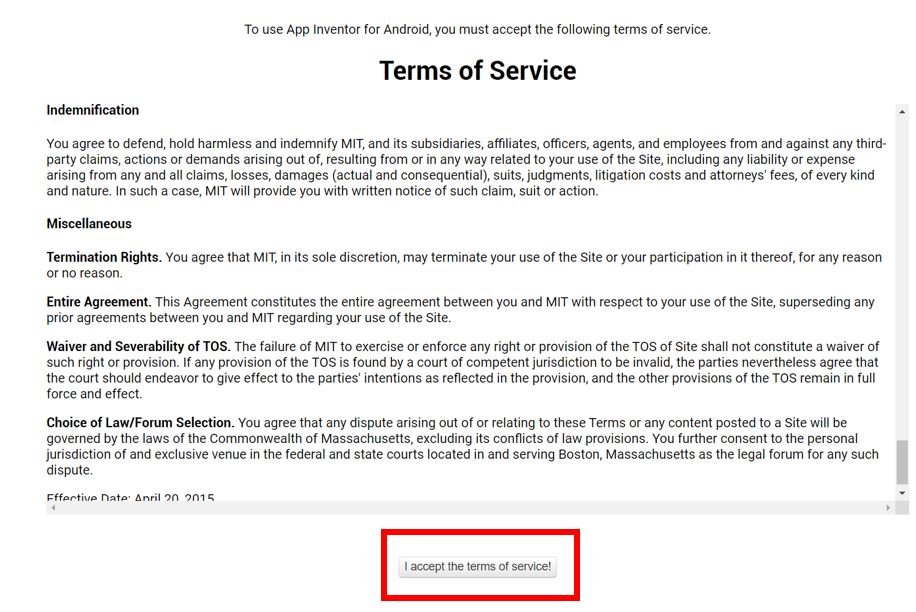
You will be redirected to a new window where you will be asked to sign in with your email account. After signing in you will have to accept the terms as shown below.
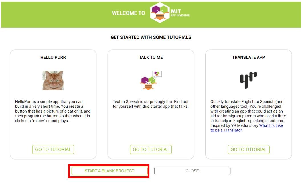
You will receive a welcome message. You can visit the link to get more information on how to install the inventor on your smartphone. Press ‘Continue’ to proceed. If you want, you can have a look at the tutorials being specified. Otherwise, go to ‘Start a blank project’ to start your app invention.
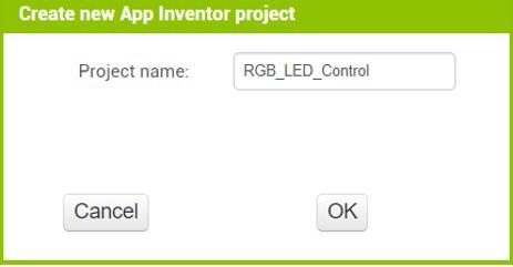
You will be asked to specify your project name. Choose an appropriate name. Click ‘ok.’
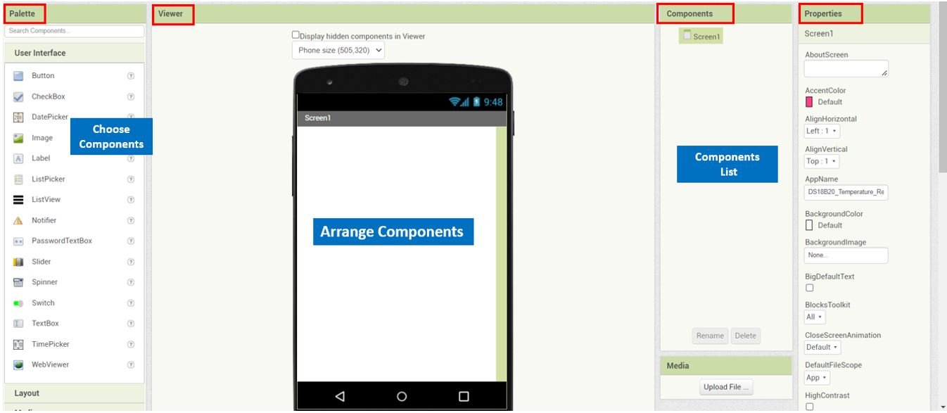
The following page will open. It is known as the Designer. This is where we will design the user interface of our app. We can add text, buttons, images and various other functionalities to our app by dragging and dropping components from the palette to the viewer. Then we will set their attributes through the ‘Properties’ column.
Creating User Interface
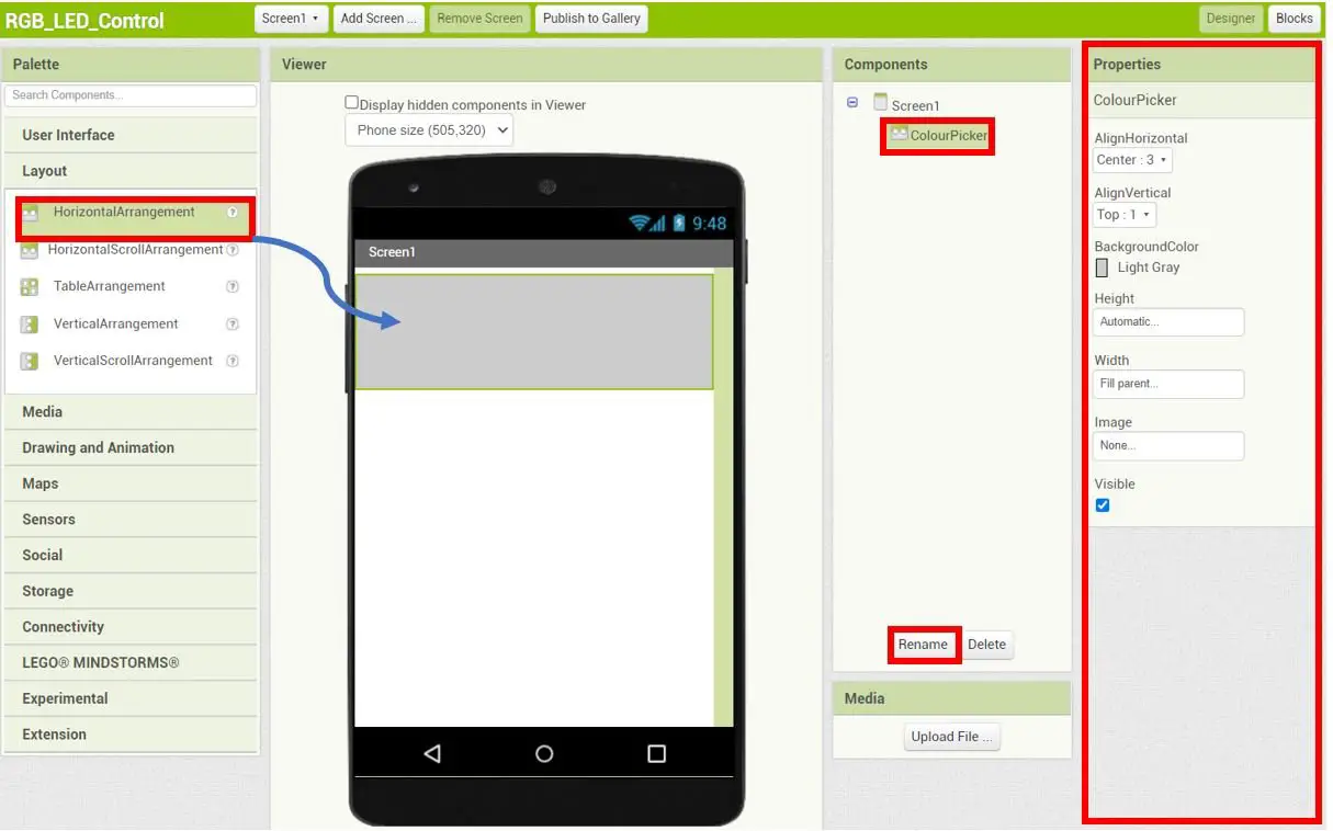
Go to Palette > Layout and head over to ‘HorizontalArrangement.’ Now drag and drop it on the Viewer side. Now you will be able to view it in the viewer as well as in the components list. We have renamed it ‘ColourPicker’ as shown in the Components sections. The Properties section shows the properties we have set for this arrangement.
Keep in mind the viewer will show you the final look of your app which will appear on your smartphone.
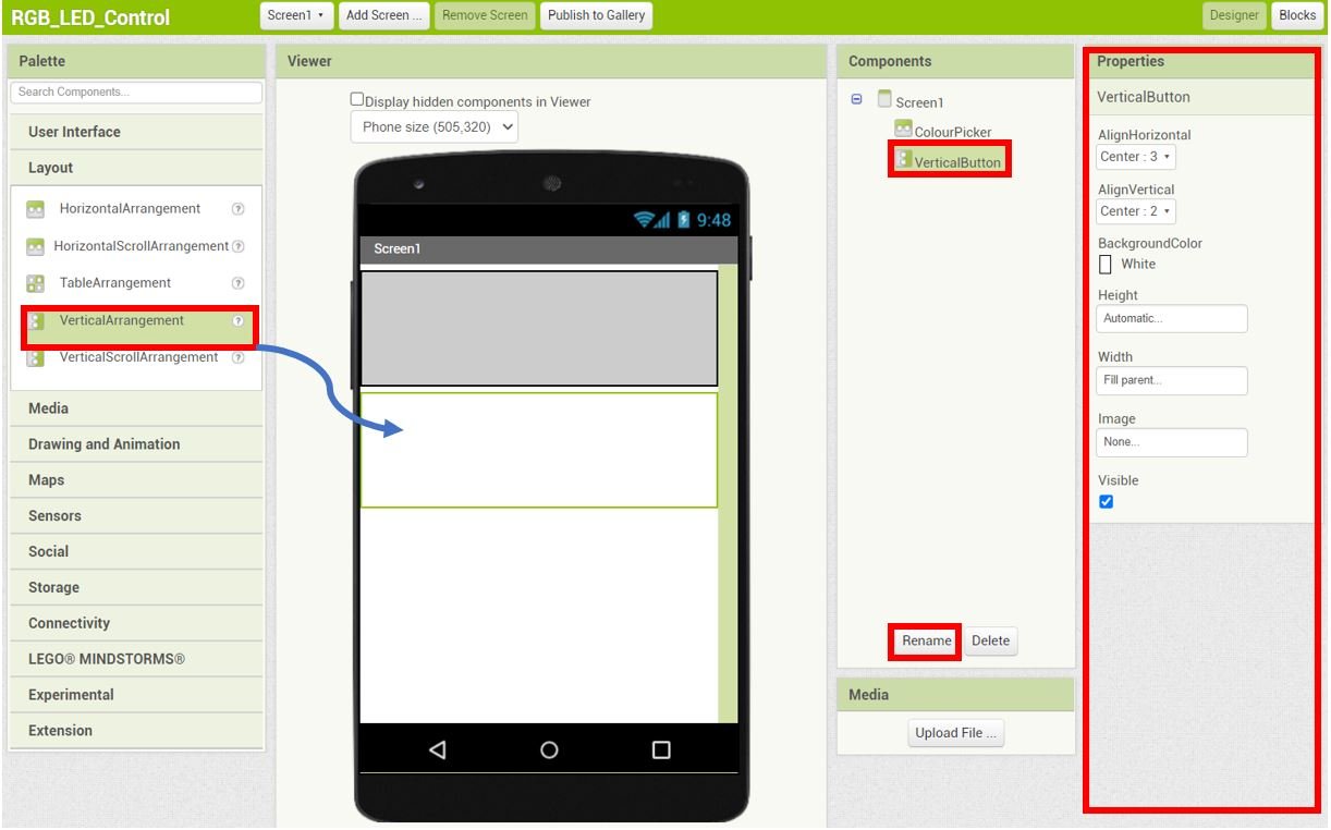
Next select VerticalArrangement from the Layout. Rename it ‘VerticalButton‘ and set the Properties as shown below.
Similarly, select VerticalScrollArrangment and drop and drag it in the viewer as shown below. We have renamed it as ‘VerticalConnect‘ as seen in the Components section. Moreover, change the properties as shown in the Properties section.

Now go to Media > Upload File and upload the three images shown below:

These are the three images that we have uploaded in the Media: ColorPicker-01.png, ColorPicker-02.png and ColorPicker-03.png


Creating the Colour Picker
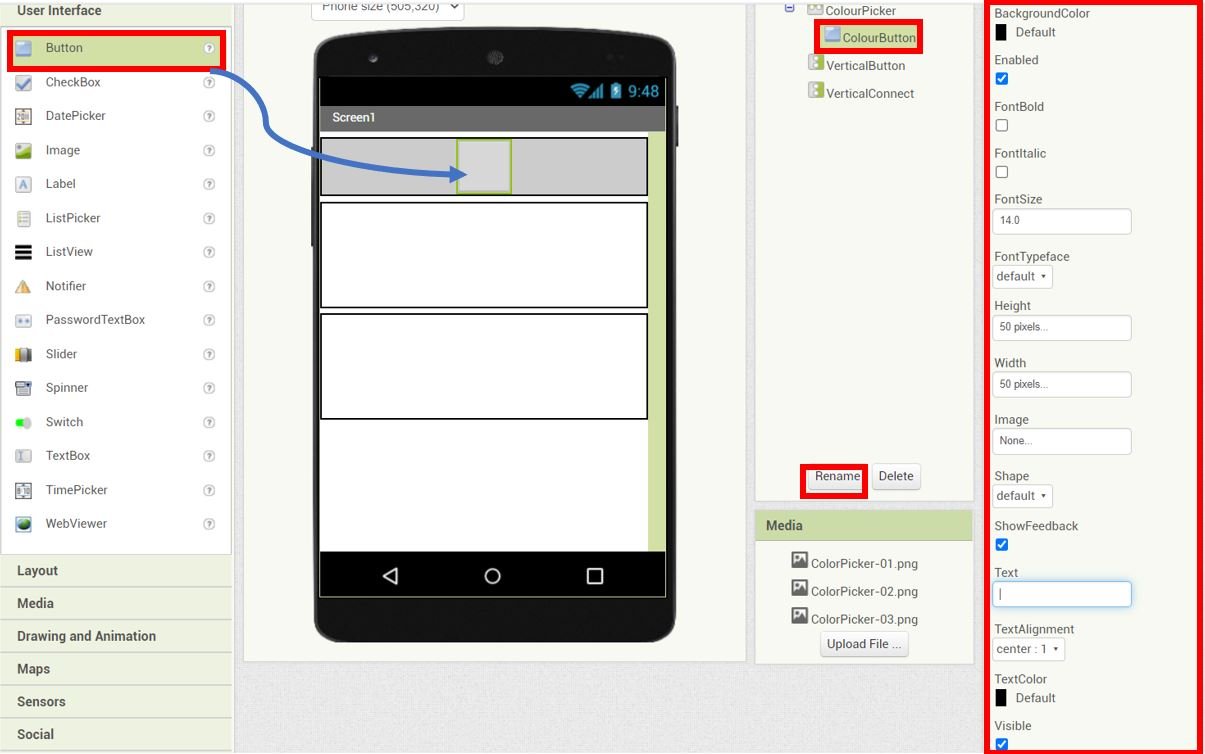
Now let us move ahead and create the colour picker that will control the RGB LED. Firstly, go to User Interface > Button, drag and drop it in the ColourPicker as shown below:
We have renamed the button to ‘ColourButton‘ and set its properties as shown in the Properties section.
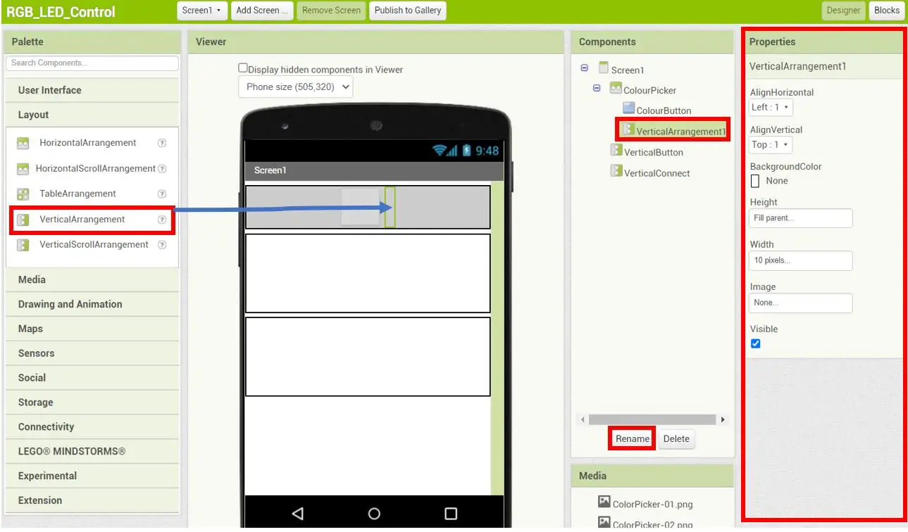
Next, select a VerticalArrangement and drag and drop it beside the ColourButton. Set its properties as shown below:
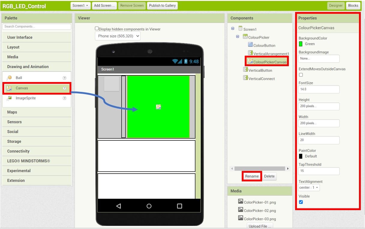
Now go to Drawing and Animation > Canvas and drag and drop it beside VerticalArrangement1 as shown below:
Rename the canvas as ‘ColourPickerCanvas‘ by using the Rename button found in the Components section. Moreover, set the properties of the ColourPickerCanvas as they are shown below:
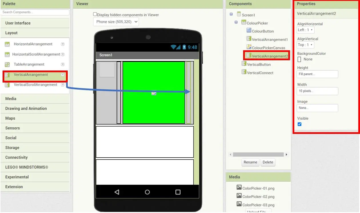
Next, select another VerticalArrangement and place it beside the ColourPickerCanvas. Set its properties accordingly.
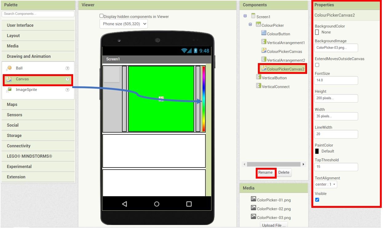
Next, go to Drawing and Animation > Canvas and put another canvas after VerticalArrangement2. Rename it as ‘ColourPickerCanvas2.’ Set its properties as shown in the Properties section. Notice that in the Properties section, in place of BackgroundImage, we have selected the image ColorPicker-03.png that we uploaded to the Media previously.
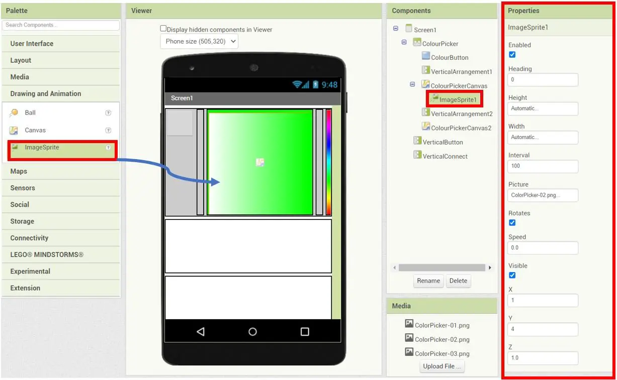
Now go to Drawing and Animation > ImageSprite and drag and drop it in the ColourPickerCanvas as shown. Set its properties as shown below. In place of Picture, we have selected ColorPicker-02.png.
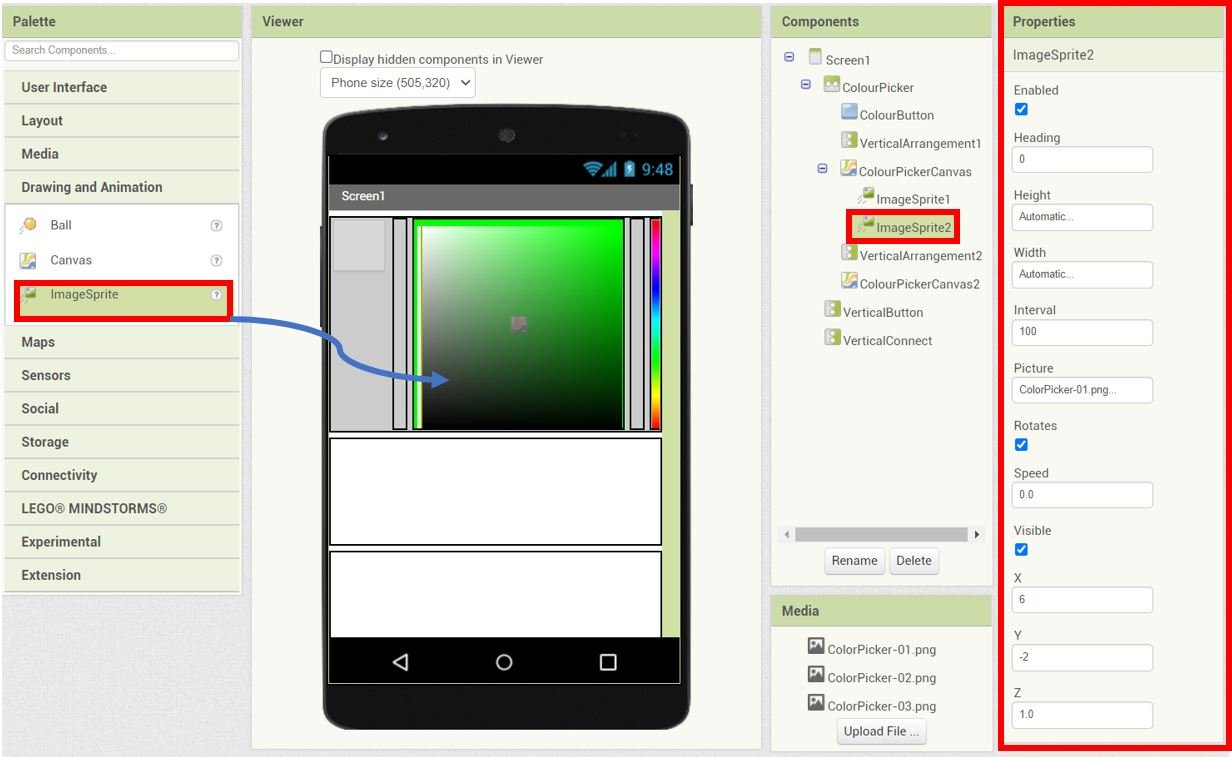
Likewise, drag and drop another ImageSprite in the ColourPickerCanvas. Carefully, set its properties as shown below with the Picture as ColorPicker-01.png.
Creating RGB Value and Change Colour Buttons
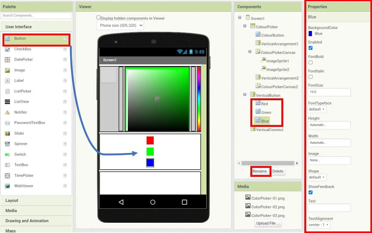
Next, let us move ahead to the VerticalButton arrangement. Go to User Interface > Button and drag and drop three buttons in the VerticalButton arrangement. Rename the buttons as ‘Red‘, ‘Green‘ and ‘Blue‘ respectively. Moreover, change the properties of the buttons as well accordingly. These buttons will show the RGB parameters for the selected colour.
The picture below shows the Properties of the Blue button.
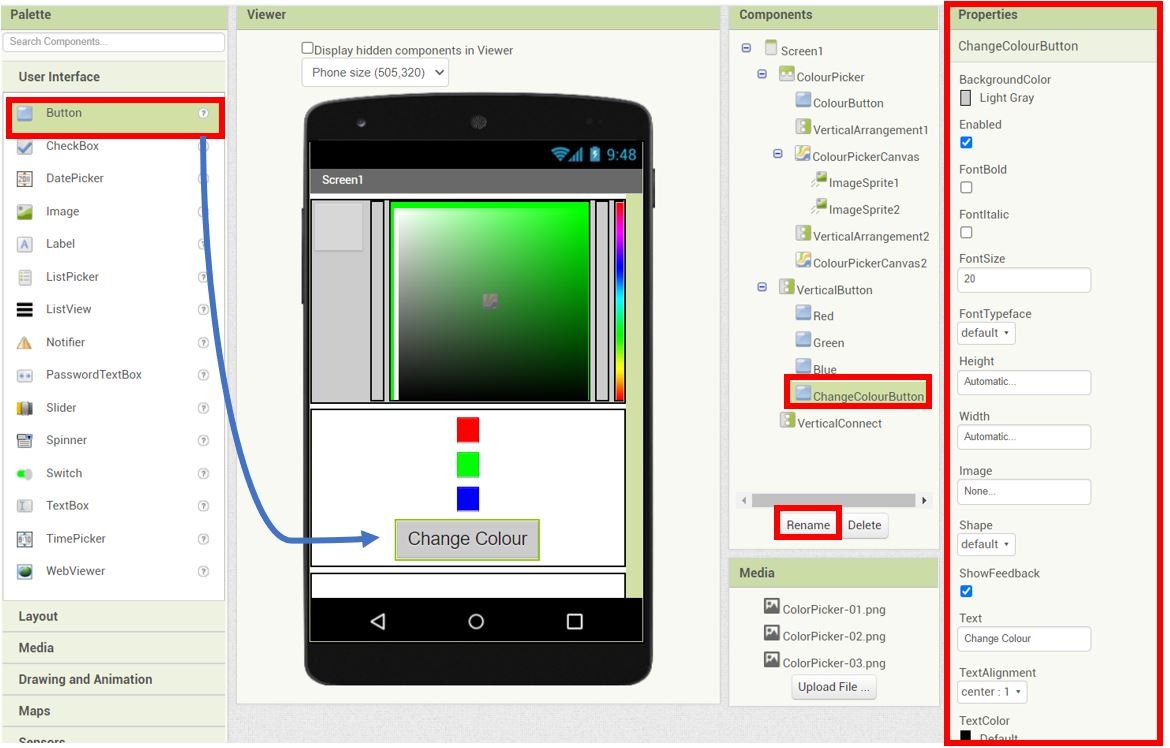
Drag and drop another Button in the Viewer as shown below. Rename it as ‘ChangeColourButton‘ and edit its properties as shown below. This button will allow the user to change the colour of the RGB LED according to the RGB parameters shown in the three buttons above.
Add Bluetooth Connection Button
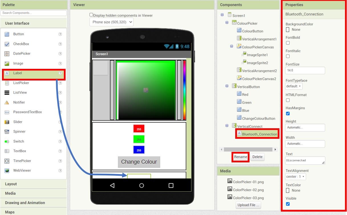
Add a label in the VerticalConnect arrangement and rename it as ‘Bluetooth_Connection‘ using the rename button found in the Components section.
Head over to the ‘Properties’ to change the text, font, font size and color of the this label. We have set the FontSize to 14, FontTypeface to Default, Height to Automatic, Width to Automatic, Text to Disconnected, TextAlignment to center : 1 and TextColor to None.
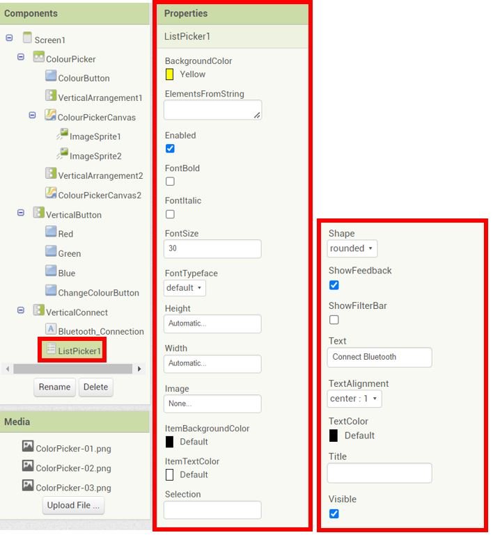
For the Connect Bluetooth button we will add a List Picker. Go to User Interface > ListPicker and drag and drop it beneath the Bluetooth_Connection label. Go to the ‘Properties’ of the ListPicker and set them as follows:
Add Bluetooth Client and Clock to MIT App Inventor
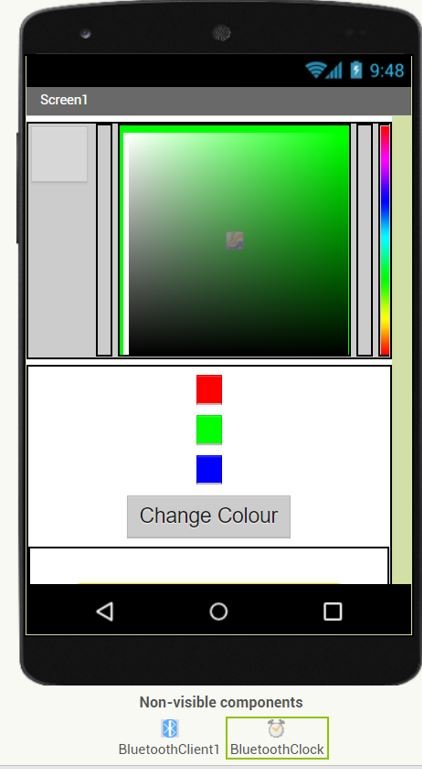
Go to Palette > Connectivity and click and drag BluetoothClient in the viewer. This is a non-visible component of our app and will let us connect it with our Bluetooth module.
Next head over to Palette > Sensors and drag and drop clock in the viewer. Rename it as ‘BluetoothClock.’ This is also a non-visible component of the app used for monitoring the time.
Blocks Layout
Now click on the ‘Blocks’ button found at the top of the window. A new editor will open up. Here we will design how our app will respond. We will assemble blocks in the workspace by clicking and dragging them.

Firstly, assemble the blocks for the Bluetooth connection as shown below.

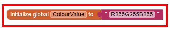
Next, inside the Blocks section, go to Built-in > Variables and select the initialize global name to block. Click and drag it to the viewer.

Here we are initializing the global variable ‘ColourValue‘ to store the RGB values. Initially it holds the value R255G255B255. This variable will store the current colour of the RGB LED.
Next, assemble the blocks for Screen1 as shown below. These blocks aim to set the width of height of ImageSprite1 and ImageSprite2 to that of ColourPickerCanvas width and height during startup.

Blocks for Colour Selection
Next, we will assemble blocks for selecting the colour.
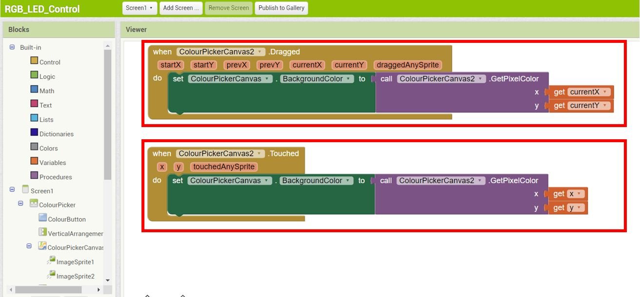
Assemble blocks for the ColourPickerCanvas2 when it gets dragged or touched. Notice that ColourPickerCanvas2 denotes the colour spectrum that is located at the extreme right of our screen. It is used to select the colour. When the user drags or touches the ColourPickerCanvas2, the background colour of ColourPickerCanvas (colour intensity setter) will be changed according to the one which is selected from the colour spectrum. These two blocks are responsible for that.
Now when the ColourPickerCanvas (colour intensity setter) is dragged or touched, the ColourButton (square found at the extreme left) changes its colour to the intensity which is selected. The text of Red, Green and Blue buttons is also set according to the RGB values of the colour selected.
Notice that the call colorPickerCanvas.GetPixelColor x, y block is used to obtain the colour from the current selected pixel. Whereas split color block is the one that splits a color into its RGB parameters.


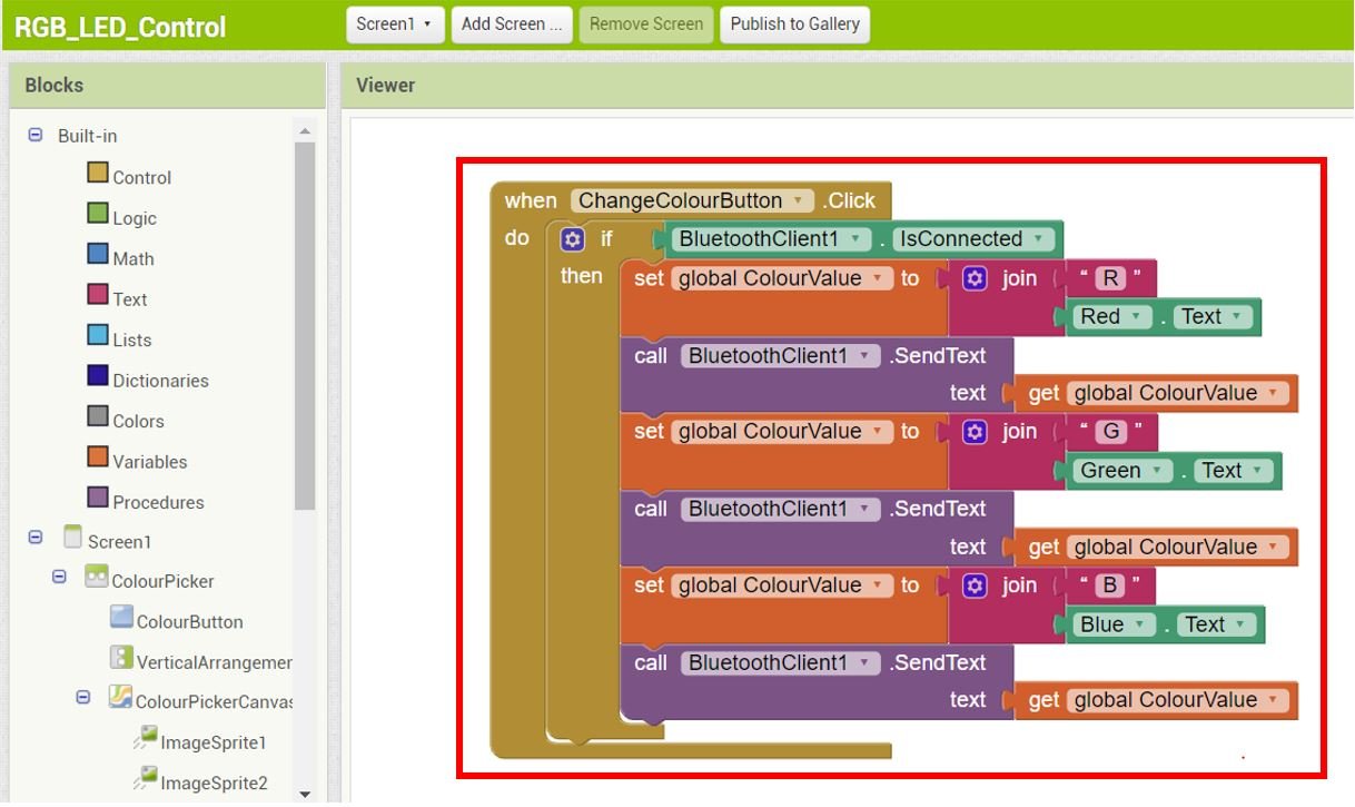
Lastly, assemble the blocks for the ChangeColourButton. When the user clicks the change colour button, the Bluetooth module receives the RGB parameters in the form RxxxGxxxBxxx where ‘x’ represents the RGB value according to the colour selected.
For more information regarding building your app in MIT App Inventor, follow this guide: App Inventor Tutorials.
Setting up App Inventor on Smartphone
Now, as we have built our app in MIT app inventor and have also written its code let’s move ahead and install the App Inventor in our smartphone. Through this, we will be able to access our app on our smartphone from anywhere around the world. Follow the steps closely.
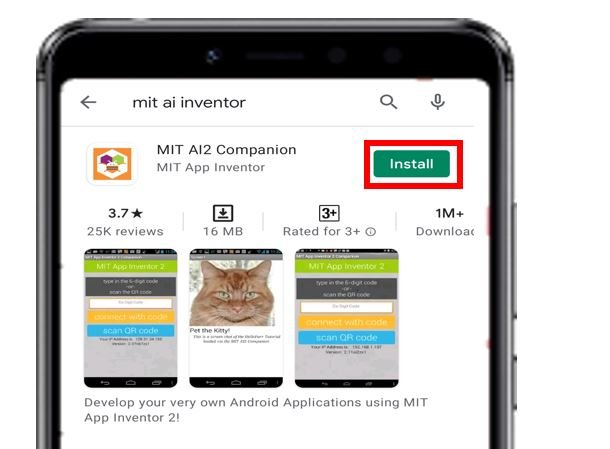
Firstly, go to Play Store and install ‘MIT AI2 Companion.’
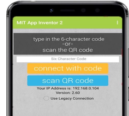
After you installed the application, open it. You will have to either scan a QR code or type a 6-character code.
To access these, go to MIT App Inventor main page where we initially built our app. Go to Build > Android App (.apk). After a few moments your barcode will get generated. You can either download the .apk file or scan the barcode using the MIT App Inventor.
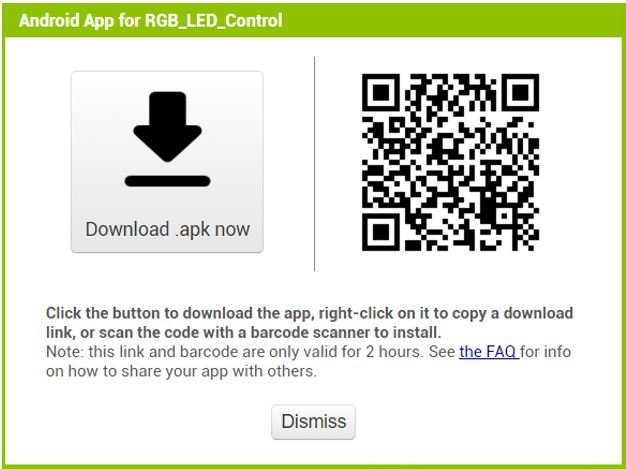
After installing the .apk file on our android phone, we will be able to view the screen which we created.
Now, we will demonstrate the RGB LED Control.
Demonstration
Choose the correct board and COM port before uploading your code to the board.
Go to Tools > Board and select Arduino Module.

Next, go to Tools > Port and select the appropriate port through which your board is connected.
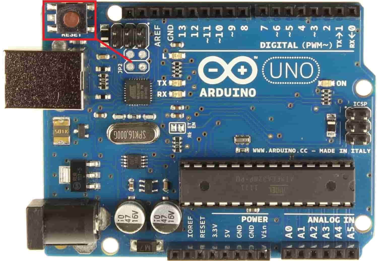
Click on the upload button to upload the code into the Arduino development board. After you have uploaded your code to the Arduino development board press its ENABLE button.
Open the MIT Companion app on your smartphone. Pair your android phone with HC-05 module. Now press the ‘Connect Bluetooth’ button.

Select HC-05 Bluetooth module to connect with.

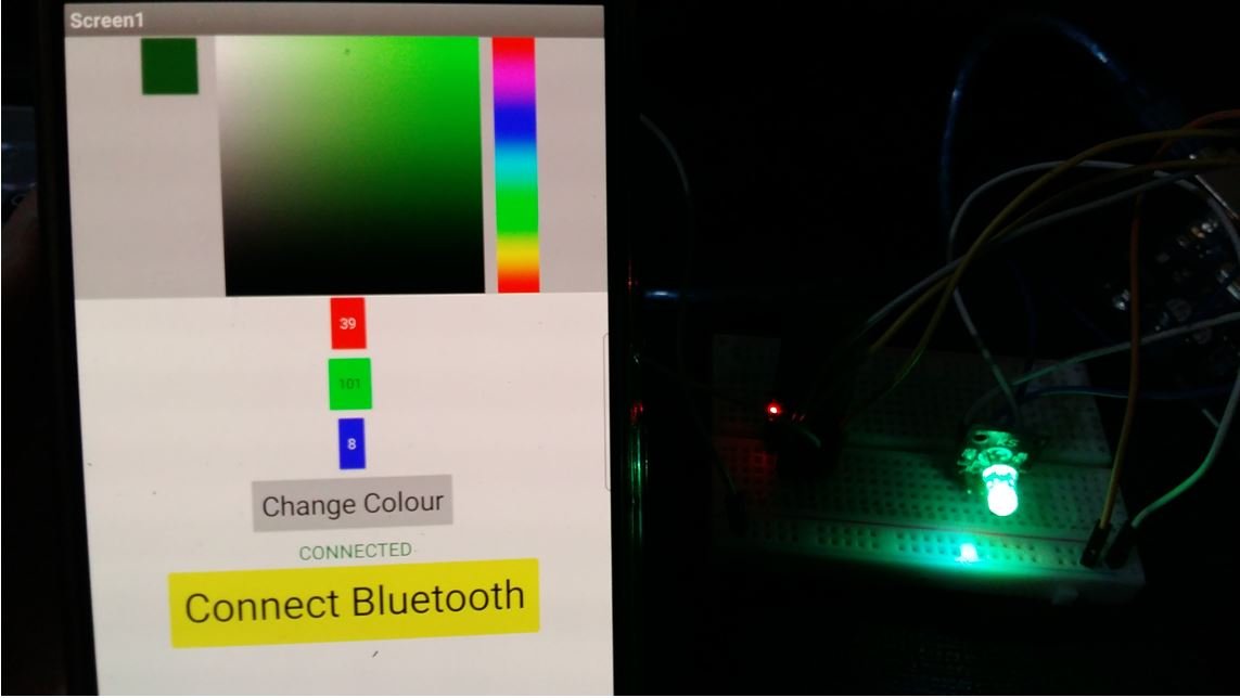
Now pick different colors from this color spectrum, set its intensity and the RGB LED will emit the same light as that color.
Video demo:
You may also like to read:
The “ino” file stops compiling at
byte index = 0;
The error message:
‘byte index’ redeclared as different kind of symbol
hey when I try to click the Bluetooth button, it only show a black screen