In this ESP32 tutorial, we will create an RGB LED controller web server. The web server will display a color spectrum that will be used to set the color of the RGB LED. The colors will primarily be divided into three: red, green, and blue. The user will pick a color from the spectrum which will be sent to the ESP32 board in the form of red, green, and blue values. This will change the color of the RGB LED based on the color values that were picked.
Introducting RGB LED
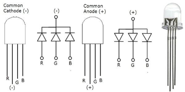
RGB LED is a light-emitting diode that emits red, green, and blue lights. It consists of three discreet LEDs: red, green, and blue housed in a single packet so by combining these three colors we can create any color. Whenever voltage is applied to the red terminal, a red light will emit, and similarly when the voltage is applied to the Green and blue terminal, green and blue lights will emit respectively.
The RGB LED has four pins. These pins are used in order to control the color of the LED. The longest pin is either the anode or the cathode depending on the type of the RGB LED.
There is two types of RGB light-emitting diodes are available in the market.
- Common Anode type: In common Anode type, Anode is common for all three Light emitting diodes and Anode of all the light emitting diodes connects with positive power supply. Other terminals connects with microcontroller and we turn on and off these terminals according to which LED we want to turn on or turn off.
- Common Cathode type: In common Cathode type, Cathode of all three light emitting diodes are common and common cathode terminal is connected with ground of power supply and other terminal of each power LED is connected with pic microcontroller according to which LED we want to turn on or turn off.
Picture of both common anode and common cathode types RGB LED is shown below:
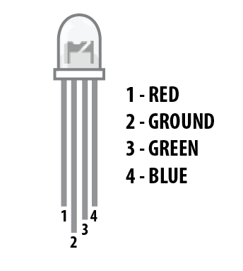
Pinout
RGB LED and its pinout is shown below.
| Pin | Description |
| 1 | This is the red color select pin. Connect with digital output pin of microcontroller. |
| 2 | This is the ground pin for the common cathode type and the 5 volts Vdd pin for the common anode type. |
| 3 | This is the Blue color select pin. Connect with digital output pin of microcontroller. |
| 4 | This is the Green color select pin. Connect with digital output pin of microcontroller. |
Recommended Components
The following components are used in this project or are helpful for building it with the ESP32.
| Component | How it’s used in this project | Buy on Amazon |
|---|---|---|
| ESP32 Development Board (DevKit V1) | The main controller that runs the project code and connects to the components. | Check Price |
| Micro USB Cable | Connects the ESP32 to your computer for programming and power. | Check Price |
| Breadboard | Lets you build the circuit and wire up parts without soldering. | Check Price |
| Jumper Wires | Make the connections between the ESP32 and the components on the breadboard. | Check Price |
| RGB LED | The LED whose color is set remotely through the ESP32 web server. | Check Price |
As an Amazon Associate we earn from qualifying purchases. Prices and availability are accurate as of the date/time indicated and are subject to change.
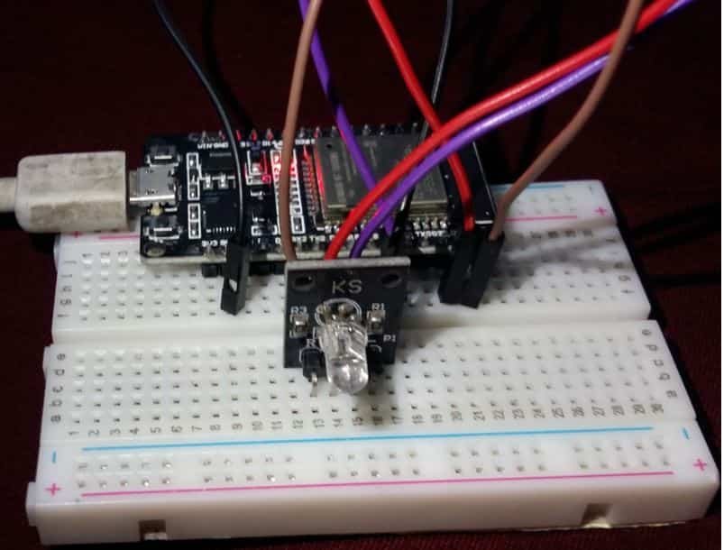
RGB LED interfacing with ESP32
We will require the following components for this web server project:
Required Components
- ESP32 development board
- Common cathode RGB LED
- Three 220 ohm resistors
- Connecting Wires
The red, green, and blue pins of the RGM LED will be connected with PWM enabled pins of ESP32. We will use GPIO23, GPIO22, and GPIO21 to connect with each color pin. You can use any appropriate GPIO pin.
Point to Note:
- In order to limit the current that will run through the RGB LED , we will need to use three resistors one for each colour pin. If we do not use a resistor or if we use a low resistor value the LED will be destroyed. We need to use a 220 ohm resistor or higher. The higher the resistor value, lower the brightness of the LED.
The schematic diagram below shows the connection between RGB LED and ESP32 module.

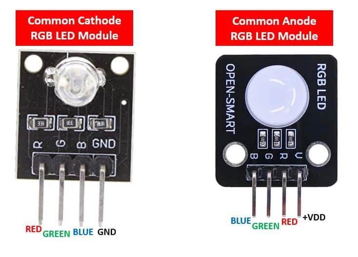
Additionally, the RGB LED also comes in a module with the current limiting resistors already attached. They are also available in two kinds: the common cathode module and the common anode module.
Below you can view the two modules with their pin outs.
Follow the schematic diagram below, if you are using the common cathode RGB LED module.
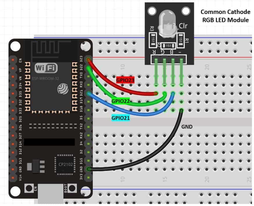
The RGM LED module already comes with the current limiting resistors so we do not to add external resistors.
We have used the RGB LED Module for our web server project.
You may like to read other RGB LED guides:
- RGB LED interfacing with MSP430G2 LaunchPad
- RGB LED interfacing with pic microcontroller – Multi color LED
- WS2812B Addressable RGB LED Interfacing with Arduino
Setting up Arduino IDE for ESP32 RGB LED Controller Web Server
We will use Arduino IDE to program our ESP32 development board. Thus, you should have the latest version of Arduino IDE. Additionally, you also need to install the ESP32 plugin. You can visit the link shown below to have a look.
Arduino Sketch ESP32 RGB LED Web Server
Open your Arduino IDE and go to File > New. A new file will open. Copy the code given below in that file and save it.
This code will set up our ESP32 board as a server that will accept URL as a parameter.
#include <WiFi.h>

#include <WebServer.h>

const char* ssid = "Your_SSID";
const char* password = "Your_Password";

const byte DNS_PORT = 53;
const int red_pin = 23;
const int green_pin = 22;
const int blue_pin = 21;

// Setting PWM frequency, channels and bit resolution
const int frequency = 5000;
const int redChannel = 0;
const int greenChannel = 1;
const int blueChannel = 2;
const int resolution = 8;


WebServer webServer(80);

String webpage = ""
"<!DOCTYPE html><html><head><title>RGB control</title><meta name='mobile-web-app-capable' content='yes' />"
"<meta name='viewport' content='width=device-width' /></head><body style='margin: 0px; padding: 0px;'>"
"<canvas id='colorspace'></canvas></body>"
"<script type='text/javascript'>"
"(function () {"
" var canvas = document.getElementById('colorspace');"
" var ctx = canvas.getContext('2d');"
" function drawCanvas() {"
" var colours = ctx.createLinearGradient(0, 0, window.innerWidth, 0);"
" for(var i=0; i <= 360; i+=10) {"
" colours.addColorStop(i/360, 'hsl(' + i + ', 100%, 50%)');"
" }"
" ctx.fillStyle = colours;"
" ctx.fillRect(0, 0, window.innerWidth, window.innerHeight);"
" var luminance = ctx.createLinearGradient(0, 0, 0, ctx.canvas.height);"
" luminance.addColorStop(0, '#ffffff');"
" luminance.addColorStop(0.05, '#ffffff');"
" luminance.addColorStop(0.5, 'rgba(0,0,0,0)');"
" luminance.addColorStop(0.95, '#000000');"
" luminance.addColorStop(1, '#000000');"
" ctx.fillStyle = luminance;"
" ctx.fillRect(0, 0, ctx.canvas.width, ctx.canvas.height);"
" }"
" var eventLocked = false;"
" function handleEvent(clientX, clientY) {"
" if(eventLocked) {"
" return;"
" }"
" function colourCorrect(v) {"
" return Math.round(1023-(v*v)/64);"
" }"
" var data = ctx.getImageData(clientX, clientY, 1, 1).data;"
" var params = ["
" 'r=' + colourCorrect(data[0]),"
" 'g=' + colourCorrect(data[1]),"
" 'b=' + colourCorrect(data[2])"
" ].join('&');"
" var req = new XMLHttpRequest();"
" req.open('POST', '?' + params, true);"
" req.send();"
" eventLocked = true;"
" req.onreadystatechange = function() {"
" if(req.readyState == 4) {"
" eventLocked = false;"
" }"
" }"
" }"
" canvas.addEventListener('click', function(event) {"
" handleEvent(event.clientX, event.clientY, true);"
" }, false);"
" canvas.addEventListener('touchmove', function(event){"
" handleEvent(event.touches[0].clientX, event.touches[0].clientY);"
"}, false);"
" function resizeCanvas() {"
" canvas.width = window.innerWidth;"
" canvas.height = window.innerHeight;"
" drawCanvas();"
" }"
" window.addEventListener('resize', resizeCanvas, false);"
" resizeCanvas();"
" drawCanvas();"
" document.ontouchmove = function(e) {e.preventDefault()};"
" })();"
"</script></html>";

void handleRoot() {
String red_pin = webServer.arg(0);
String green_pin = webServer.arg(1);
String blue_pin = webServer.arg(2);

if((red_pin != "") && (green_pin != "") && (blue_pin != ""))
{
  ledcWrite(redChannel, 1023 - red_pin.toInt());
  ledcWrite(greenChannel, 1023 - green_pin.toInt());
  ledcWrite(blueChannel, 1023 - blue_pin.toInt());
}
Serial.print("Red: ");
Serial.println(red_pin.toInt());
Serial.print("Green: ");
Serial.println(green_pin.toInt());
Serial.print("Blue: ");
Serial.println(blue_pin.toInt());
Serial.println();

webServer.send(200, "text/html", webpage);
}

void setup() {
  ledcSetup(redChannel, frequency, resolution);
  ledcSetup(greenChannel, frequency, resolution);
  ledcSetup(blueChannel, frequency, resolution);

  ledcAttachPin(red_pin, redChannel);
  ledcAttachPin(green_pin, greenChannel);
  ledcAttachPin(blue_pin, blueChannel);

delay(1000);
Serial.begin(115200);
Serial.println();

WiFi.mode(WIFI_STA);
  WiFi.begin(ssid, password);
  Serial.print("Connecting to WiFi ..");
  while (WiFi.status() != WL_CONNECTED) {
    Serial.print('.');
    delay(1000);
  }
  Serial.println(WiFi.localIP());


webServer.on("/", handleRoot);
webServer.begin();
}

void loop() {

webServer.handleClient();
}
How the Code Works?
Firstly, we will include the necessary libraries. As we have to connect our ESP32 to a wireless network, we need WiFi.h library for that purpose. The WebServer.h will be required to build the web server.
#include <WiFi.h>

#include <WebServer.h>
Next, we will create two global variables, one for the SSID and another for the password. These will hold our network credentials which will be used to connect to our wireless router. Replace both of them with your credentials to ensure a successful connection.
const char* ssid = "Your_SSID";
const char* password = "Your_Password";
The following lines specify the GPIO pins of ESP32 connected with each of the colour pins of the RGM LED. Here we are using the same GPIO pins as shown in the schematic diagrams above. You can use any suitable output pin of ESP32.
const int red_pin = 23;
const int green_pin = 22;
const int blue_pin = 21;
Defining PWM parameters
The following variables define the PWM frequency, channels and the bit resolution. The brightness of the LED will be controlled through the duty cycle. When we define the PWM parameters for each LED it includes the frequency of the signal, led channels and resolution. We have set the frequency at 5000 Hz. For defining the PWM channel we can choose between a total of sixteen PWM channels in ESP32. You can use any channel from 0-15. We have set the PWM channel to 0, 1, 2 for three LEDs respectively. Additionally, we have set the PWM resolution to 8 bits as it is the optimal resolution to obtain the maximum frequency. Although you can use resolution between 1-16 bits. As we are using 8-bit resolution, thus the duty cycle value will vary between 0-255 which we will map to 0-100%.
Recommended Reading: ESP32 PWM with Arduino IDE – LED fading example
const int frequency = 5000;
const int redChannel = 0;
const int greenChannel = 1;
const int blueChannel = 2;
const int resolution = 8;
The WebServer object will be used to set up the ESP32 web server. We will pass the default HTTP port which is 80, as the input to the constructor. This will be the port where the server will listen to the requests.
WebServer webServer(80);HTML
The following HTML code builds the web server.
String webpage = ""
"<!DOCTYPE html><html><head><title>RGB control</title><meta name='mobile-web-app-capable' content='yes' />"
"<meta name='viewport' content='width=device-width' /></head><body style='margin: 0px; padding: 0px;'>"
"<canvas id='colorspace'></canvas></body>"
"<script type='text/javascript'>"
"(function () {"
" var canvas = document.getElementById('colorspace');"
" var ctx = canvas.getContext('2d');"
" function drawCanvas() {"
" var colours = ctx.createLinearGradient(0, 0, window.innerWidth, 0);"
" for(var i=0; i <= 360; i+=10) {"
" colours.addColorStop(i/360, 'hsl(' + i + ', 100%, 50%)');"
" }"
" ctx.fillStyle = colours;"
" ctx.fillRect(0, 0, window.innerWidth, window.innerHeight);"
" var luminance = ctx.createLinearGradient(0, 0, 0, ctx.canvas.height);"
" luminance.addColorStop(0, '#ffffff');"
" luminance.addColorStop(0.05, '#ffffff');"
" luminance.addColorStop(0.5, 'rgba(0,0,0,0)');"
" luminance.addColorStop(0.95, '#000000');"
" luminance.addColorStop(1, '#000000');"
" ctx.fillStyle = luminance;"
" ctx.fillRect(0, 0, ctx.canvas.width, ctx.canvas.height);"
" }"
" var eventLocked = false;"
" function handleEvent(clientX, clientY) {"
" if(eventLocked) {"
" return;"
" }"
" function colourCorrect(v) {"
" return Math.round(1023-(v*v)/64);"
" }"
" var data = ctx.getImageData(clientX, clientY, 1, 1).data;"
" var params = ["
" 'r=' + colourCorrect(data[0]),"
" 'g=' + colourCorrect(data[1]),"
" 'b=' + colourCorrect(data[2])"
" ].join('&');"
" var req = new XMLHttpRequest();"
" req.open('POST', '?' + params, true);"
" req.send();"
" eventLocked = true;"
" req.onreadystatechange = function() {"
" if(req.readyState == 4) {"
" eventLocked = false;"
" }"
" }"
" }"
" canvas.addEventListener('click', function(event) {"
" handleEvent(event.clientX, event.clientY, true);"
" }, false);"
" canvas.addEventListener('touchmove', function(event){"
" handleEvent(event.touches[0].clientX, event.touches[0].clientY);"
"}, false);"
" function resizeCanvas() {"
" canvas.width = window.innerWidth;"
" canvas.height = window.innerHeight;"
" drawCanvas();"
" }"
" window.addEventListener('resize', resizeCanvas, false);"
" resizeCanvas();"
" drawCanvas();"
" document.ontouchmove = function(e) {e.preventDefault()};"
" })();"
"</script></html>";
handleRoot()
The handleRoot() function takes in no parameters. It is responsible for ESP32 handling the /root URL. We will configure the root / URL where our server will listen to HTTP GET requests.
It will be responsible for reading the RGB arguments from the web server. The red, green and blue arguments will be read when the user selects the colour. This gets printed on the serial monitor. By using ledcWrite() we will generate the PWM with the duty cycle values accessed from the colour picker values. The handling function will respond to the client by using the send() method on the server. This method will take in three parameters. The first is 200 which is the HTTP status code for ‘ok’. The second is “text/html” which will correspond to the content type of the response. The third input is the webpage which will be sent as the response.
void handleRoot() {
String red_pin = webServer.arg(0);
String green_pin = webServer.arg(1);
String blue_pin = webServer.arg(2);

if((red_pin != "") && (green_pin != "") && (blue_pin != ""))
{
  ledcWrite(redChannel, 1023 - red_pin.toInt());
  ledcWrite(greenChannel, 1023 - green_pin.toInt());
  ledcWrite(blueChannel, 1023 - blue_pin.toInt());
}
Serial.print("Red: ");
Serial.println(red_pin.toInt());
Serial.print("Green: ");
Serial.println(green_pin.toInt());
Serial.print("Blue: ");
Serial.println(blue_pin.toInt());
Serial.println();

webServer.send(200, "text/html", webpage);
}
setup()
By using ledcSetup(), we will initialize the PWM parameters for the three LEDs. This function takes in three parameters. The channel number, frequency, and resolution of the PWM channel.
  ledcSetup(redChannel, frequency, resolution);
  ledcSetup(greenChannel, frequency, resolution);
  ledcSetup(blueChannel, frequency, resolution);
Secondly, we will use ledcAttach() to attach the led pins to the respective channels.
  ledcAttachPin(red_pin, redChannel);
  ledcAttachPin(green_pin, greenChannel);
  ledcAttachPin(blue_pin, blueChannel);
Inside the setup() function, we will open a serial connection at a baud rate of 115200.
Serial.begin(115200);The following section of code will connect our ESP32 board with the local network whose network credentials we already specified above. After the connection will be established, the IP address of the ESP32 board will get printed on the serial monitor. This will help us to make a request to the server. we are setting our ESP32 module in station mode.
WiFi.mode(WIFI_STA);
  WiFi.begin(ssid, password);
  Serial.print("Connecting to WiFi ..");
  while (WiFi.status() != WL_CONNECTED) {
    Serial.print('.');
    delay(1000);
  }
  Serial.println(WiFi.localIP());
To start the server, we will call begin() on our server object.
webServer.on("/", handleRoot);
webServer.begin();
loop()
Inside the loop() function we will call handleClient() on the server object so that the server can listen to the HTTP requests continuously.
void loop() {

webServer.handleClient();
}
Demonstration
Make sure you choose the correct board and COM port before uploading your code to the board. Go to Tools > Board and select ESP32 Dev Module.

Next, go to Tools > Port and select the appropriate port through which your board is connected.

Click on the upload button to upload the code into the ESP32 development board.
After you have uploaded your code to the development board, press its ENABLE button.

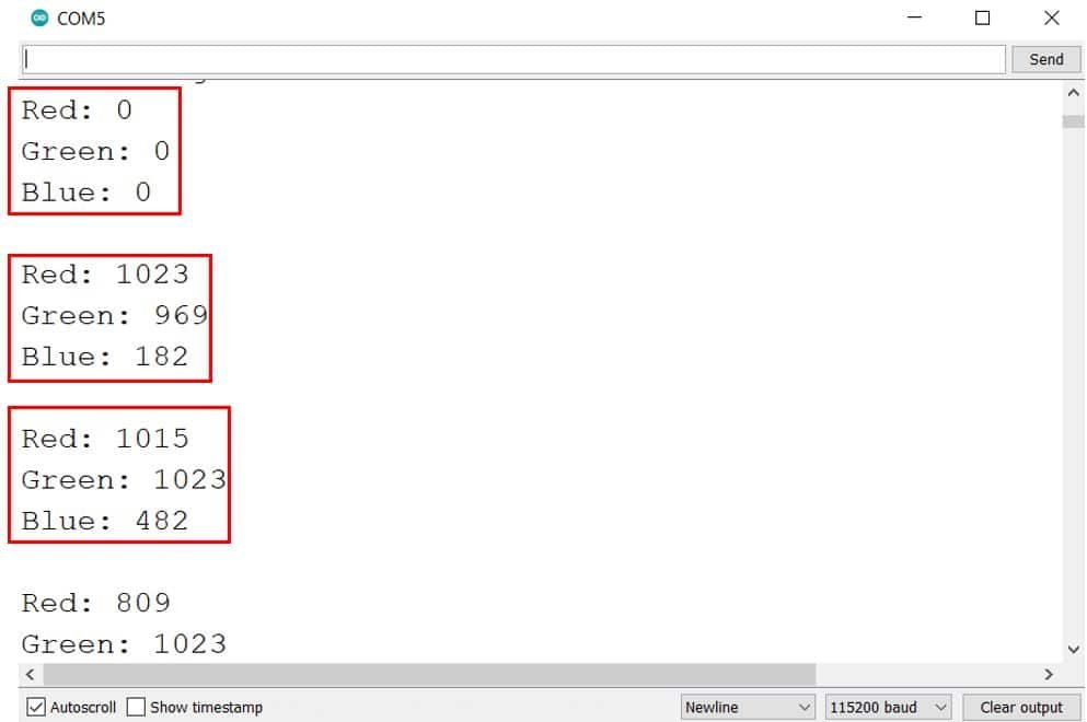
In your Arduino IDE, open up the serial monitor and you will be able to see the IP address of your ESP32 module.

Type this IP address in a new web browser and press enter. The following web page will open up.

Now pick different colors from this color spectrum and the RGB LED will emit the same light as that color.
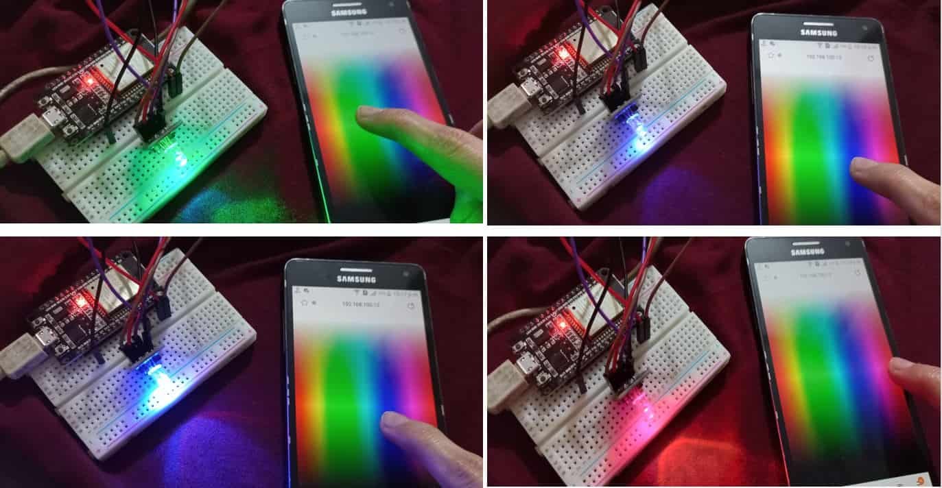
The serial monitor will also display the values of each individual LED whenever you select a colour.
You can watch the video of it as well:
You may like to read other ESP32 web server projects that we published:
- ESP32 MPU6050 Web Server Accelerometer and Gyroscope Dashboard with 3-D animation (SSE Events)
- ESP32 Stepper Motor WebSocket Web Server using Arduino IDE
- ESP32 BLE Server Client Communication using Arduino IDE
- IoT Based Analog and Digital Clock using OLED and ESP32/ESP8266
- ESP32 IoT Motion Detection Web Server with Email Alert
Excelente Tutorial! Parabéns
Hey for what is DNS_PORT??? Cheers
How to correct the color output if using a common anode LED?
Compilation error: ‘ledcSetup’ was not declared in this scope any ideas?
Excellent project, very well written and clearly explained. I ported it to platformIO with the following .ini file. The correct version of the espressif code is essential other erors with ledc arise.
[env:esp32doit-devkit-v1]
platform = espressif32@6.5.0
board = esp32doit-devkit-v1
framework = arduino
I hope this helps someone.
upload_port = COM3