Automatic street light control is a good concept that aims to bring efficiency and convenience to our everyday lives. In this article, we explore a simple yet effective circuit diagram that employs transistors and light-dependent resistors (LDRs) to automate the operation of street lights. Unlike previous designs that relied on microcontrollers, this analog-based approach utilizes readily available electronic components to achieve automatic street light control. Whether you’re a technology enthusiast or simply interested in enhancing energy efficiency, this article will provide valuable insights into the workings of this innovative system.
Automatic street light control circuit diagram. In this article, we are going to post a very simple circuit diagram of automatic street light control using transistors and light-dependent resistors. This is a very simple circuit of automatic street light control. we have already posted other articles on automatic street light control and auto intensity control of street lights. These articles used PIC microcontrollers and Arduino Uno R3. However, in this article, only analog electronic components are used to control street lights. You may also check the following articles on street light control.
- Automatic street light control using pic microcontroller and LDR
- Automatic street light control using Arduino and LDR
- Auto intensity control of street lights using pic microcontroller
What is automatic street light control?
Gone are the days when people used to control electrical devices manually. Today is the automated age. People want things to control themselves automatically. For this purpose, automatic street lights projects have been designed. Automatic street lights turn themselves on and off automatically by sensing the intensity of light with the help of light sensors. There are many light sensors available in the market. But in this project, I have used an LDR (Light Dependent Resistor).

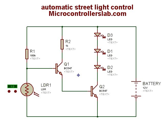
Circuit Diagram of Automatic Street Light Control
The circuit diagram of automatic street light control is given below. This is a very simple circuit with a few electronic components.
Working
The circuit diagram represents a simple automatic street light control system using transistors and a light-dependent resistor (LDR). Here is an explanation of its working:
- LDR: The LDR is a light-sensitive resistor that changes its resistance based on the intensity of light falling on it. When the light level is high, the resistance of the LDR decreases, and when the light level is low, the resistance increases.
- BC547 NPN Transistors: The circuit uses two BC547 NPN transistors, Q1 and Q2.
- Q1 Transistor: Q1 acts as a switch. When the light intensity is above a certain threshold, the resistance of the LDR is low, and Q1 turns off. As a result, Q2 turns off as well.
- Q2 Transistor: Q2 also acts as a switch. When Q2 is off, the three light-emitting diodes (LEDs) connected to it are also off. This simulates the street lights being turned off.
- Operation: During the day or in bright light conditions, the LDR has low resistance, which causes Q1 to turn off. As a result, Q2 remains off, and the LEDs do not light up. This represents the street lights being off during the day.
- At night or in low light conditions, the resistance of the LDR increases. This causes Q1 to turn on, which in turn activates Q2. As a result, the LEDs connected to Q2 start to light up, simulating the street lights being turned on.
- Power Supply: The circuit is powered by a 12V battery.
In summary, the LDR senses the ambient light level, and based on that, the transistors control the lighting of the LEDs to automate the street lights.
LDR (Light-dependent resistor) is used to sense the intensity of light. When the intensity of light falls below the minimum level, the BC547 NPN transistor turns on, which in turn activates the Q2 NPN transistor. Three light emitting diodes (LEDs) are used in this project. A 12-volt battery is used to power this circuit diagram. You can increase the number of LEDs as well. Transistors are utilized as switches. The list of components for the automatic street light control circuit is given below:
List of Components
Category,Reference,Value,Order Code
Resistors,"R1",100k,
Resistors,"R2",1k,
Transistors,"Q1",BC547,
Transistors,"Q2",BC547,
Diodes,"D1",LED,
Diodes,"D2",LED,
Diodes,"D3",LED,
Miscellaneous,"BATTERY",12V,
Miscellaneous,"LDR1",LDR,
Conclusion
In conclusion, automatic street light control is a promising concept that not only enhances energy efficiency but also adds convenience to our everyday lives. By utilizing a simple yet effective circuit diagram with transistors and light-dependent resistors, this analog-based approach allows for the automation of street lights without the need for complex microcontrollers.
Related content:
- Zero Crossing Detection Circuits Examples
- Rain Drop Sensor Module Interfacing with PIC Microcontroller — Rain Detector Circuit
- Automatic Power Source Selector Circuit using Arduino
- Automatic Plant Watering System Circuit Diagram
- Password-based Circuit Breaker using PIC Microcontroller
- Best Free Electronics Circuit Simulation Software
- Frequency to Voltage Converter Circuits
Sir What is the configuration of circuit
Common Base Common Emitter Common Collector
standard components for an LED automatic stree light.