In this tutorial, we will look at a frequency to voltage converter. It is an electronic device that converts the sinusoidal input frequency into a proportional current or output voltage. The basic circuit includes operational amplifiers and RC circuits (resistors, capacitor networks). The operational amplifiers are useful for signal processing. We can also use the RC networks to remove the frequency dependent ripples. The diagram below shows the basic circuit of a frequency to voltage converter using op-amp and RC networks:
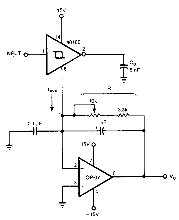
The input frequency given to this converter can be in the range of 0–10 kHz. And the output can be between 0 and -10 V.
Block Diagram of F-V Converter
In this section, we will discuss the block diagram of a F-V converter.
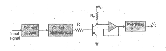
The above block diagram shows a frequency to voltage converter. The circuit charges the capacitor to a certain level. The circuit has an integrator in it, and the capacitor discharges into this integrator, or a low-pass circuit. This happens for all the cycles of the input waveform. The precision switch and the monostable multivibrator generate a pulse of a specific amplitude and period. This pulse is fed into the averaging network. Hence, we get a DC voltage at the output.
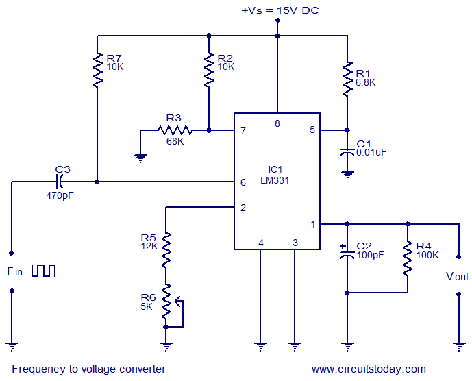
F-V Circuit Diagram Using LM331
This is the circuit diagram of a frequency to voltage converter using LM331.
This IC is basically a voltage to frequency converter, but we can also use it as a frequency to voltage converter. Its applications also include analog-to-digital conversion and long-term integration.
F-V Converter Working
In this circuit, LM331 converts frequency into voltage. The voltage on the output is proportional to the frequency at the input. It is an 8-pin IC. The source connects to pin 8 and supplies 15 V DC. Pins 3 and 4 connect to the ground. The input frequency is given at pin 6, and we take the output voltage from pin 1. The input frequency is differentiated by using the resistor R7 and capacitor C3. Then the resultant pulse train goes to pin 6. The trigger occurs in the timer circuit of the built-in comparator circuit in the IC when the negative edge of the pulse train appears at pin 6.
The current flowing out of pin 6 is proportional to the values of capacitor C1 and resistor R1 (which are the timing components) and the input frequency. Therefore, we get the output voltage across the resistor R4, which is proportional to the frequency of the input. We generally use 15V DC in this circuit, but the operating voltage of the IC is between 5V and 30V DC. The value of the resistor R3 depends on the supply voltage.
Applications of F-V Converters
These converters are useful in a wide range of applications, such as communication, power control, measurement and instrumentation systems, etc.
We will discuss the following applications in detail:
- Frequency to voltage converter in tachometers.
- Frequency difference measurement.
F-V Converter and Digital Tachometer
A digital tachometer is an electronic device that measures the rate of rotation of a wheel. They display the rate of rotation in the form of voltage, which is why they require a frequency to voltage converter in them. The diagram below shows a digital tachometer.

The rate of occurrence of some events is measurable by a rate meter. It counts the events for a certain time period and then divides the number of events by the total time, and hence we get a rate. This is the theory of operation of a simple tachometer.
We are using an IC LM2907 for this tachometer circuit. It is an 8-pin IC. At pin 1, we apply a frequency signal at the charge pump’s input. At pin 2, the voltage will be between two values: ¼ (VCC) – VBE and ¾ (VCC) – VBE.
The diagram below shows the configuration of the IC LM2907:
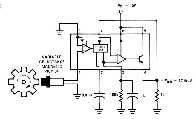
The capacitors C1 and C2 and the resistor R1 have specific values according to the circuit requirements. We can study these values from the data sheet for LM2907.
Interfacing of LM2907
This IC requires an input signal at pin 1, and at pin 11, we apply a reference voltage. Pin 8 and pin 9 require a constant voltage supply. The op amp’s inverting input connects with the output of the emitter. We get a low impedance voltage at pin 5, which is proportional to the given input frequency. From pins 5 and 10, we get an output signal of 67 Hz/V. This output is sent to the ADC, and then the DSP can read this output.
Frequency Difference Measurement
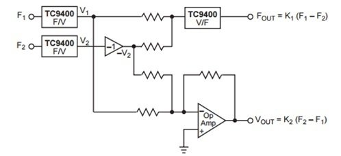
TC9400 is a frequency to voltage and voltage to frequency converter IC. Its basic circuit connections include three resistors, two capacitors, and a reference voltage. We can use two TC9400 ICs and operate both of them in the mode of frequency to voltage conversion in order to obtain the frequency difference measurements.
We use two converters, and we get V1 and V2 as two separate outputs. A unity gain inverts the voltage V2 coming from the 2nd F/V converter. An op-amp connects, which adds both the voltage V1 and the inverted –V2 voltage. This sum will be proportional to the actual frequency difference between F1 and F2. A V/F converter also connects to the circuit, which gives the frequency output, which is again proportional to the frequency difference between F1 and F2. Hence, we get the frequency difference measurement in terms of frequency as well as in terms of voltage. The diagram below shows the circuit for frequency difference measurement.
Besides these two applications, there are numerous other applications of F/V converters, such as frequency dividers and multipliers, frequency decoders, frequency meters, motor speed control, etc., which are easily available on several web pages.
Conclusion
In conclusion, this tutorial provides an in-depth overview of the frequency to voltage converter. It convers the block and circuit diagram along with its workings and applications to help us better understand the concept of F-V converters. You can utilize this for your projects where frequency to voltage converters are required. Hopefully, this was helpful in expanding your knowledge.
You may also like to read:
- STM32 Blue Pill Timer Input Capture Mode with Frequency Measurement Example
- Frequency Measurement using TM4C123 Timers in Input-Edge Capture Mode
- Raspberry Pi Pico W SMTP Client Send Sensor Readings via Email
- BME680 Web Server with ESP32 ( Arduino IDE)
- ESP32 with MPU6050 Accelerometer, Gyroscope, and Temperature Sensor (Arduino IDE)
This concludes today’s article. If you face any issues or difficulties, let us know in the comment section below.
I enjoyed reading the content of it. I was amazed by it.
Keep it up. Love to see more post from you. Thank you for sharing.
yes thanks
I have one question….ic 40106 ground pin that is 7 is not mentioned in the figure plz help me out im preparing the same circut….
The question above by Kamra refrs to the first schematic.
I think that pin 7 of the IC 40106 is used and thet “8” is mistyped.
Hi Mr. Bilal,
I interested in F/V converter, is it possible that for me to change the value of external resistors and capacitors in the figure (F-V CIRCUIT DIAGRAM USING LM331) so that the Vout is in between 0-5v with fin (input frequency) in between 0-100hz?
Hi Mr. Bilal,
I interested also in F/V converter, is it possible that for me to change the value of external resistors and capacitors in the figure (F-V CIRCUIT DIAGRAM USING LM331) so that the Vout is in between 0-5v with fin (input frequency) in between 0-100hz? please email me to johnvlastos@yahoo.com
thanks in advance
john
Can it be arranged for an input frequency of 30KHz and an out put voltage of 30 or more VDc ?
Hello Mr Bilal,
same question asked by John: I’d like to modify the LM331 circuit for input frequency range 0-30 Hz and output voltage 0 to 5V = VDC power supply.
I would need 0 V at 0 Hz (I evaluated also circuits with Sample & Hold, but Vout would be unpredictable when not sampling)
Thanks if you can help me, please write in case to paolo.ossola.it@gmail.com
Thanks a lot
Paolo
Hi sir, please explain about pin number 8 in the picture of the first circuit. Thank you
“The current flowing out of pin 6…” – should be: “of pin 1”.
Rgrds
What you have shared here is used in Instrumentation and control especially for motion sensors. I have learned of new ICs I can consider in my future projects.