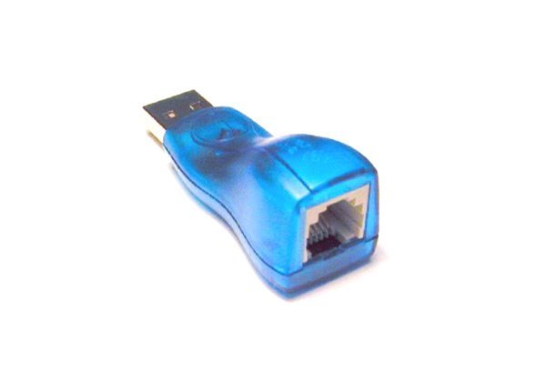
DS9490R is a USB to 1-wire adapter embedded with 1-wire technology launched by Maxim integrated. This adapter is used to connect a 1-wire output sensor to a computer through a USB port. That means this connector converts a 1-wire connection into a USB connection to be used with a USB port of a computer. The post is a guideline to its prominent features, interfacing, and applications.
Recommended Components
The following parts are used in this article, along with a generic electronics kit that is handy for building and testing the circuit.
| Component | How it’s used | Buy on Amazon |
|---|---|---|
| DS9490R USB to 1-Wire adapter | The USB-to-1-Wire/iButton adapter described in this article. | Check Price |
| Electronic component assortment kit (1390 pcs) | A handy assortment of resistors, capacitors, LEDs, diodes and transistors for building circuits. | Check Price |
| Digital multimeter (AstroAI) | Measures voltage, current, resistance and checks continuity while you build and debug. | Check Price |
| Breadboard | Solderless base for prototyping the circuit. | Check Price |
| Jumper Wires | Make the connections on the breadboard. | Check Price |
As an Amazon Associate we earn from qualifying purchases. Prices and availability are accurate as of the date/time indicated and are subject to change.
DS9490R Adapter Introduction
The adapter has a fast 12 Mbps universal serial interface to connect a 1-wire device or sensor to a laptop or personal computer. It consists of DS2401 which is a 64-bit ROM chipset and a DS2490 USB to 1-wire link that has two USB modes. Moreover, it is a low-power, easy-to-interface minimalistic device for serial device communication. It also connects the iButton to the PC. The input end of the connector consists of an RJ11 port which is used to connect a sensor and the other end consists of an USB port to be connected with a computer.
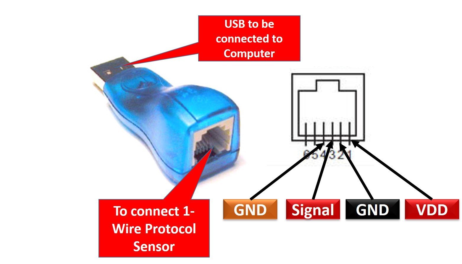
DS9490R Pinout
The pinout of the compact DS9490R USB to 1-wire connector is as shown:
Pin Configuration
The pin configuration in tabular are detailed as below:
| Pin Number | Pin Name | Function |
|---|---|---|
| 1 | VDD | RJ11 Power Supply output |
| 2 | GND | RJ11 Ground |
| 3 | OW | 1-wire Optical Wireless data |
| 4 | GND_OW | 1-wire Optical Wireless return |
| 5 | SUSO | USB Suspend Output |
| 6 | N.C | Not Connected |
DS9490R Features
The DS9490R comes with some eminent features that are listed below:
- The device is based on a DS2490 1-wire chipset.
- During active mode, it consumes up to 58 mA of current. And in the suspended state it is about 0.5 mA.
- Each DS9490 USB to 1-wire bridge has its own unique 64-bit identification number due to DS2401.
- The adapter works at a fast data rate of 12Mbps through Universal Serial Bus interface.
- It can interface 1-wire protocol sensors and devices.
- For communicating with different 1-wire peripherals, DS9490R has a programmable 1-wire timing.
- Integrated with the standard RJ11 interface for connectivity purposes.
- Contains open-drain suspended USB output which if high is in a non-suspended state and vice versa.
- It has internal pull-up resistors for better data communication.
- Read/write operations are carried out through a 1-wire bus.
DS9490R Block Diagram
The block diagram to understand the internal circuitry of the DS9490R USB to 1-wire Connector:

How to use it?
It is basically designed to connect every 1-wire bus device to the computer system. It works as a bridge between sensors/ devices and the host system and transfers data between 1-wire bus to the universal serial bus. The 1-wire sensor or device is connected through the RJ11 jack via cable and the USB is connected to the host computer. The RJ11 chipset has 6 pins. Pin 1 and 2 are VDD and GND pins to power up the sensor. Pin 3 and 4 are 1-wire protocol pins i.e Optical wire data pin which is connected to the respective pin of the 1-wire device and optical wire ground to the signal ground of the sensor. When the DS9490R is plugged through the USB jack, the system recognizes the adapter due to the presence of the DS2401 chip, and transmission starts between the host and the 1-wire device for which the adapter is being the bridge. Multiple devices or sensors can be connected to the adapter if they are joined in the form of an array.

1-wire is actually a bi-directional multidrop protocol that works in a master-slave organization. Each slave device has a specific address through which the host system can control and communicate data for functioning different operations through a single bus. Maxim has a variety of 1-wire products, so it has introduced this bridge for compatibility and ease. It has another version known as DS9490B which is particularly for the iButton.
Applications
- Serial Data Communication
- 1-wire bus interfacing
- Read/write operations
- Software authorization
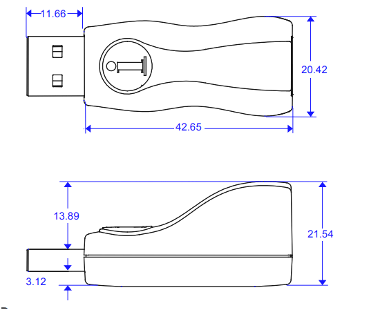
2D Diagram
Related Articles: