In this project, we will build an IoT based fall detection project using an MPU6050 sensor and ESP32 with an email alert feature. Our fall detection project will be linked with the IFTTT web service to generate an email alert to notify users whenever a fall is detected. The user will get an update whenever a fall will be detected, specifying the exact date and time of the detection.
The MPU6050 module consists of 3-axis accelerometers, a 3-axis gyroscope, and a built-in temperature sensor. All of these are present on a single chip. The module takes into account the x, y, and z channels at the same time because it has 16 bits analog converter dedicated for each channel.
The 3-axis accelerometer measures the rate of change of velocity (m/s^2) or the acceleration of the object. This measurement can be performed on both stationary and moving objects. The module also has a 3-axis gyroscope which measures the rotational velocity of an object in rad/s. This feature helps us understand the exact orientation of the object. With the help of the accelerometer and the gyroscope, we will compare the acceleration magnitude with a set threshold value. This will be able to detect a fall. Whenever a fall will be detected, the ESP32 board configured with IFTTT services will send an email alert to the user.
MPU6050 Module
MPU6050 module consists of a digital motion that performs all complex processing, computations and provides sensor data output to other MCUs over I2C communication. It is widely used in measuring the health and operating parameters of various machines. It is also used in applications of robotics and motion sensors. This sensor is based upon MEMS (Micro-Mechanical Systems) technology hence it is extremely compact and accurate in certain frequencies. It has a relatively small size and low power consumption. It communicates with other microcontrollers and sensors via I2C communication.
Some of the key features of the MPU6050 Module include:
- Built-in I2C sensor bus which is used to provide gyroscope, accelerometer, and temperature sensor data to other devices such as microcontrollers.
- Onboard pull-up resistor so we do not need to connect external pull resistors which are a requirement for the I2C bus interface.
- User Programmable gyroscope and accelerometer with the help of 16-bit analog to digital converter.
- 1024 Byte FIFO buffer to provide data to the connected microcontroller in high speed and enters the low power mode afterwards.
- Built-in temperature sensor
MPU-6050 Interfacing with ESP32
We will be requiring the following components in this project.
- ESP32 development board
- MPU6050 Module
- Breadboard
- Connecting Wires
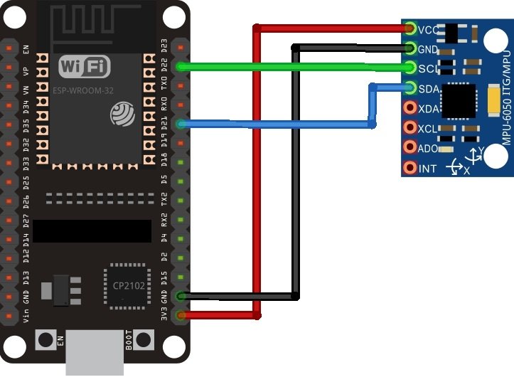
As you see, the MPU6050 has 8 terminals but in order to connect with ESP32, we will only require the first four pins highlighted in yellow. These are VCC, GND, SCL, and SDA. The table shows the connections between the two modules.
| MPU6050 Module | ESP32 Module |
|---|---|
| VCC | 3.3V |
| GND | GND |
| SCL | GPIO22 (I2C SCL) |
| SDA | GPIO21 (I2C SDA) |
The VCC pin is connected with the 3.3V from the ESP32 module to power up. Both the grounds of the two devices are connected in common. The SCL pin of MPU6050 is connected with the default SCL pin of ESP32. Likewise, the SDA pin is connected with the default SDA pin of ESP32.
Assemble the two modules as shown below:

Recommended Reading: ESP32 with MPU6050 Accelerometer, Gyroscope, and Temperature Sensor ( Arduino IDE)
Configuring IFTTT Web service for Fall Detector
IFTTT means ‘If this, then that.’ It is an open-source service that gives the user the freedom to program a response to an event according to their likes. We can create an applet which are chains of conditional statements by a combination of several app services and add triggering parameters. For our project, we will be using this service, to send email alerts whenever fall is detected. To work with this web service, we will have to follow a series of steps to ensure the proper functionality.
Creating an Account
Although the IFTTT service is free to use, we will have to create an account. First go to the following website: https://ifttt.com/
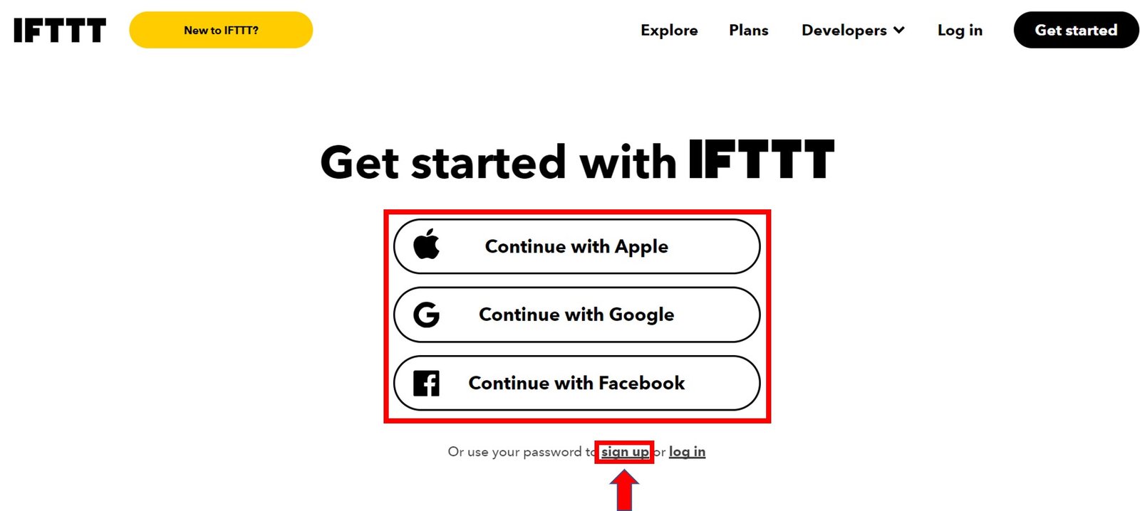
The following window will appear. Click on the ‘Get Started’ button.

The following window will appear. You can select any one from these three options (Apple, Google or Facebook) to connect. Or you can simply ‘sign up’ with your own given email. We will be following this scheme.
Click the ‘sign up’ tag. You will see the following window pop up. Enter your email address and password to start working in IFTTT. This whole process is free of cost for the first three applets.

Creating an Applet
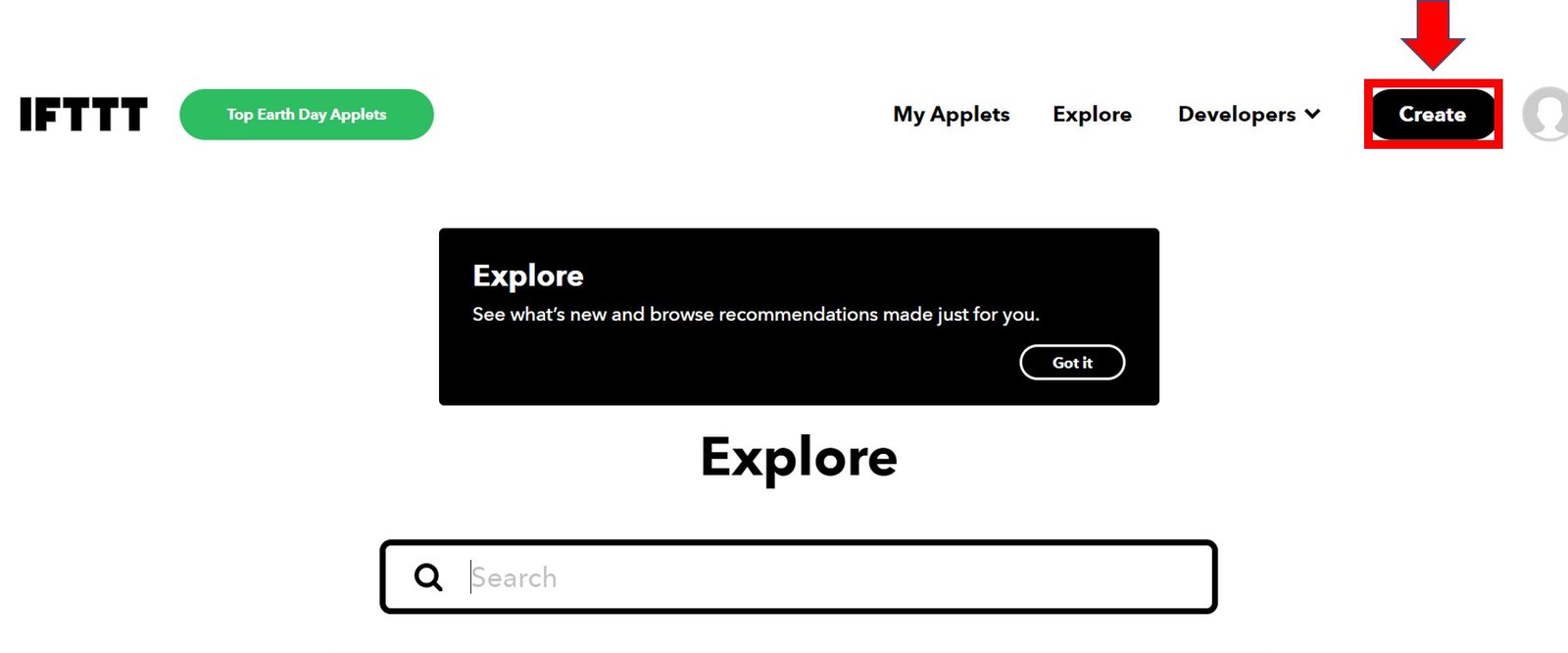
After you have created your account, we will be directed to the page where we will create our applet. Click on ‘Create.’
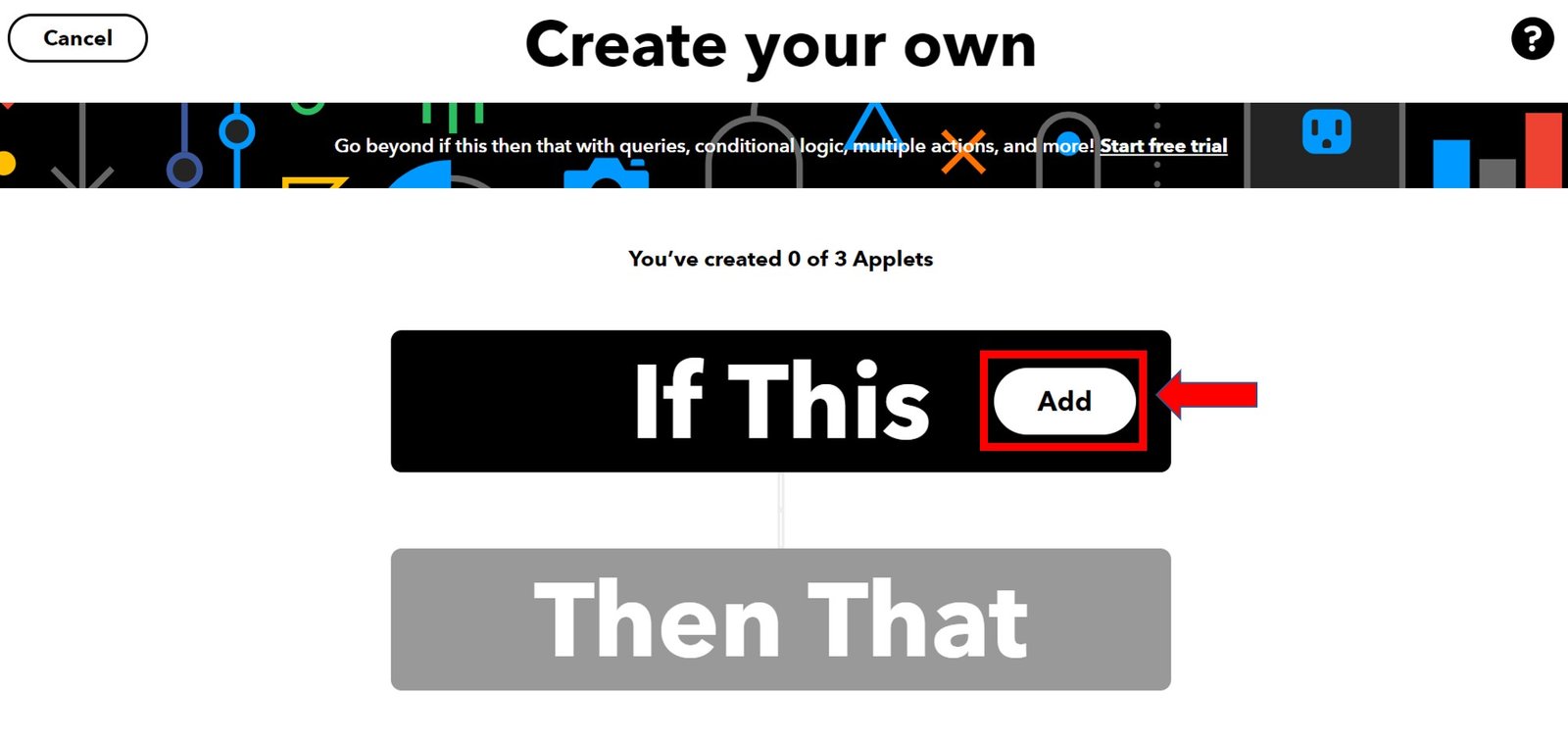
The following window opens up. Click the following Add button in the ‘If This’ section.
Another page will open in which we will have to choose our service. There is a lot of options to choose from. Write down ‘webhooks’ in the search option and its icon will appear:

Select Trigger
Next, choose the trigger as: ‘Receive a web request’ by clicking on it. Whenever webhooks will receive a web request, some action will take place. This we will define in the ‘THAT’ section.

After clicking the Receive a web request, the following window will open up. We will write down ‘FALL DETECTION’ as the event name for the web request. You can use any other name of your choice. Click ‘Create Trigger’ button.

After the trigger is created, we are taken back to the web page where we first added the service for the ‘IF THIS’ section. Now we will click the ADD button for the ‘THEN THAT’ section.

Now we will choose the service. We have to choose what will happen if a web request is received. We will type ‘email’ in the search option and click on its icon. This is because we want to receive email notification whenever a web request is received.

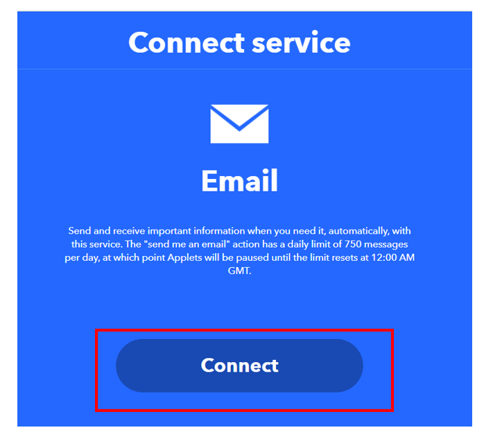
The following page opens up. Choose ‘Send me an email’ to proceed further.

Click on the ‘Connect’ button as shown below.
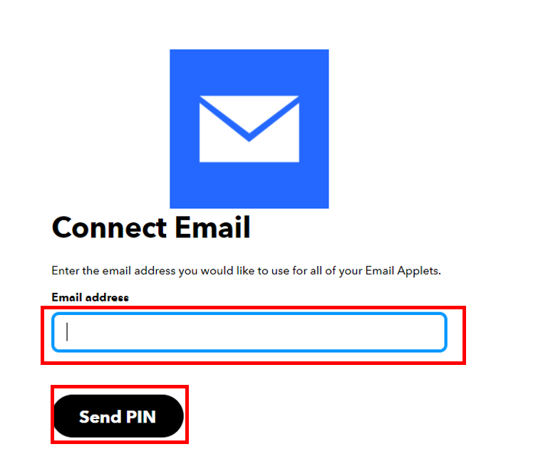
Next, write down your email address and click ‘Send Pin’ as shown below:
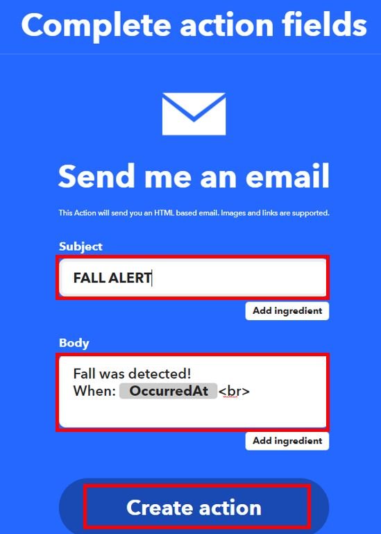
After you successfully enter the PIN, a new window will open up. Complete the action fields by specifying the subject and body of the email. Afterwards, click ‘Create Action.’
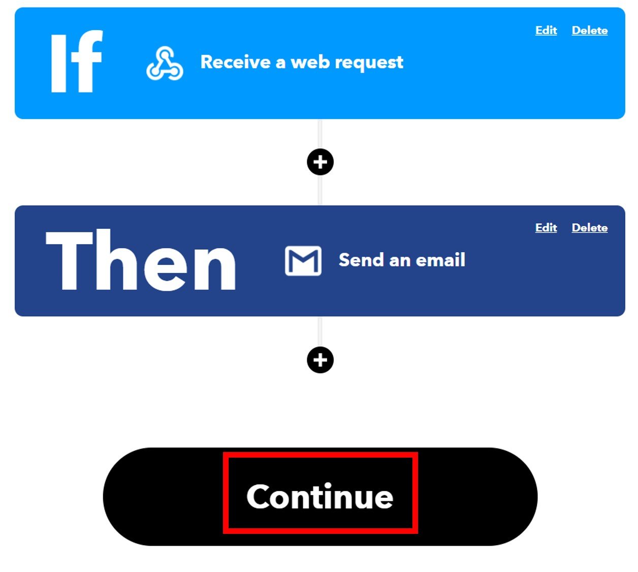
After we have created the action, we will be guided towards the initial web page of IFTTT. Click ‘Continue’ to proceed.
After this click the Finish button. Make sure to turn ON the notifications when the applet is running.
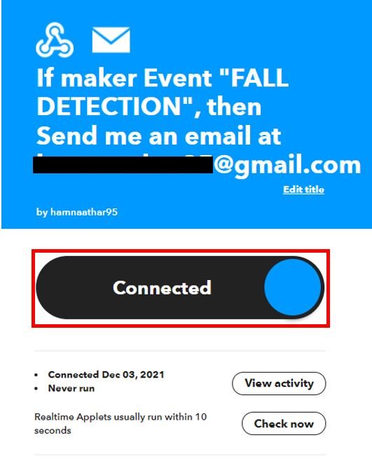
You have successfully created the applet as shown below.
Obtaining the Private Key
Before we proceed further with our project, we want to access our private key. This is important as it will be required while programming our ESP32 board.
Go to your applet and select “My Services” or open a webpage with the link: ifttt.com/my_services. The following windows will appear. Afterward, click on Webhooks.

This will take you to the following web page. Click on ‘Documentation.’

You will receive a key that should be secure with you.

You may also like to read about other project we created with IFTTT:
- ESP32/ESP8266: Publish Sensor Readings to Google Sheets via IFTTT
- ESP32 HTTP POST using Arduino IDE (ThingSpeak and IFTTT)
- MicroPython: Send Sensor Readings via Email (IFTTT) with ESP32 and ESP8266
- Send Email Alert Based on Temperature Threshold and Update Threshold value with ESP32 Web Server
Arduino Sketch for ESP32 MPU6050 Fall Detector
We will use Arduino IDE to program our ESP32 development board. Thus, you should have the latest version of Arduino IDE. Additionally, you also need to install the ESP32 plugin. You can visit the link shown below to have a look.
There will be no need to install additional libraries for this project as the ESP32 Arduino core already comes with the libraries which we require.
Open your Arduino IDE and go to File > New to open a new file. Copy the code given below in that file.
Make sure to replace your network credentials and the private key for Webhooks as well as the event name of your web request you set up in IFTTT.
#include <Wire.h>
#include <WiFi.h>

const int MPU_addr=0x68;  // I2C address of the MPU-6050
int16_t AcX,AcY,AcZ,Tmp,GyX,GyY,GyZ;
float ax=0, ay=0, az=0, gx=0, gy=0, gz=0;
boolean fall = false; //stores if a fall has occurred
boolean trigger1=false; //stores if first trigger (lower threshold) has occurred
boolean trigger2=false; //stores if second trigger (upper threshold) has occurred
boolean trigger3=false; //stores if third trigger (orientation change) has occurred
byte trigger1count=0; //stores the counts past since trigger 1 was set true
byte trigger2count=0; //stores the counts past since trigger 2 was set true
byte trigger3count=0; //stores the counts past since trigger 3 was set true
int angleChange=0;

const char *ssid =  "YOUR_SSID";     // Replace with your WIFI SSID
const char *pass =  "YOUR_PASSWORD"; // Replace with your WIFI PASSWORD

void send_event(const char *event);
const char *host = "maker.ifttt.com";
const char *privateKey = "gkb_HtIpE-FeOWMH20obLTvUR7_fPipDyj_hdTJF2od";

void setup(){
 Serial.begin(115200);
 Wire.begin();
 Wire.beginTransmission(MPU_addr);
 Wire.write(0x6B);  // PWR_MGMT_1 register
 Wire.write(0);     // set to zero (wakes up the MPU-6050)
 Wire.endTransmission(true);

  WiFi.begin(ssid, pass);
  while (WiFi.status() != WL_CONNECTED)
  {
    delay(500);
    Serial.print(".");
  }
  Serial.println("");
  Serial.println("WiFi connected");
 }
void loop(){
 mpu_read();
 ax = (AcX-2050)/16384.00;
 ay = (AcY-77)/16384.00;
 az = (AcZ-1947)/16384.00;
 gx = (GyX+270)/131.07;
 gy = (GyY-351)/131.07;
 gz = (GyZ+136)/131.07;
 // calculating Amplitute vactor for 3 axis
 float raw_amplitude = pow(pow(ax,2)+pow(ay,2)+pow(az,2),0.5);
 int amplitude = raw_amplitude * 10;  // Mulitiplied by 10 bcz values are between 0 to 1
 Serial.println(amplitude);
 if (amplitude<=2 && trigger2==false){ //if AM breaks lower threshold (0.4g)
   trigger1=true;
   Serial.println("TRIGGER 1 ACTIVATED");
   }
 if (trigger1==true){
   trigger1count++;
   if (amplitude>=12){ //if AM breaks upper threshold (3g)
     trigger2=true;
     Serial.println("TRIGGER 2 ACTIVATED");
     trigger1=false; trigger1count=0;
     }
 }
 if (trigger2==true){
   trigger2count++;
   angleChange = pow(pow(gx,2)+pow(gy,2)+pow(gz,2),0.5);
   Serial.println(angleChange);
   if (angleChange>=30 && angleChange<=400){ //if orientation changes by between 80-100 degrees
     trigger3=true; trigger2=false; trigger2count=0;
     Serial.println(angleChange);
     Serial.println("TRIGGER 3 ACTIVATED");
       }
   }
 if (trigger3==true){
    trigger3count++;
    if (trigger3count>=10){
       angleChange = pow(pow(gx,2)+pow(gy,2)+pow(gz,2),0.5);
       Serial.println(angleChange);
       if ((angleChange>=0) && (angleChange<=10)){ //if orientation changes remains between 0-10 degrees
           fall=true; trigger3=false; trigger3count=0;
           Serial.println(angleChange);
             }
       else{ //user regained normal orientation
          trigger3=false; trigger3count=0;
          Serial.println("TRIGGER 3 DEACTIVATED");
       }
     }
  }
 if (fall==true){ //in event of a fall detection
   Serial.println("FALL DETECTED");
   send_event("FALL DETECTION");
   fall=false;
   }
 if (trigger2count>=6){ //allow 0.5s for orientation change
   trigger2=false; trigger2count=0;
   Serial.println("TRIGGER 2 DECACTIVATED");
   }
 if (trigger1count>=6){ //allow 0.5s for AM to break upper threshold
   trigger1=false; trigger1count=0;
   Serial.println("TRIGGER 1 DECACTIVATED");
   }
  delay(100);
   }
void mpu_read(){
 Wire.beginTransmission(MPU_addr);
 Wire.write(0x3B);  // starting with register 0x3B (ACCEL_XOUT_H)
 Wire.endTransmission(false);
 Wire.requestFrom(MPU_addr,14,true);  // request a total of 14 registers
 AcX=Wire.read()<<8|Wire.read();  // 0x3B (ACCEL_XOUT_H) & 0x3C (ACCEL_XOUT_L)
 AcY=Wire.read()<<8|Wire.read();  // 0x3D (ACCEL_YOUT_H) & 0x3E (ACCEL_YOUT_L)
 AcZ=Wire.read()<<8|Wire.read();  // 0x3F (ACCEL_ZOUT_H) & 0x40 (ACCEL_ZOUT_L)
 Tmp=Wire.read()<<8|Wire.read();  // 0x41 (TEMP_OUT_H) & 0x42 (TEMP_OUT_L)
 GyX=Wire.read()<<8|Wire.read();  // 0x43 (GYRO_XOUT_H) & 0x44 (GYRO_XOUT_L)
 GyY=Wire.read()<<8|Wire.read();  // 0x45 (GYRO_YOUT_H) & 0x46 (GYRO_YOUT_L)
 GyZ=Wire.read()<<8|Wire.read();  // 0x47 (GYRO_ZOUT_H) & 0x48 (GYRO_ZOUT_L)
 }
void send_event(const char *event)
{
  Serial.print("Connecting to ");
  Serial.println(host);
  WiFiClient client;
  const int httpPort = 80;
  if (!client.connect(host, httpPort)) {
    Serial.println("Connection failed");
    return;
  }
  String url = "/trigger/";
  url += event;
  url += "/with/key/";
  url += privateKey;
  Serial.print("Requesting URL: ");
  Serial.println(url);
  client.print(String("GET ") + url + " HTTP/1.1\r\n" +
               "Host: " + host + "\r\n" +
               "Connection: close\r\n\r\n");
  while(client.connected())
  {
    if(client.available())
    {
      String line = client.readStringUntil('\r');
      Serial.print(line);
    } else {
      delay(50);
    };
  }
  Serial.println();
  Serial.println("closing connection");
  client.stop();
}
How the Code Works?
The first step is to include the necessary libraries. Include the following ESP32 libraries for the proper functionality of the project.
#include <Wire.h>
#include <WiFi.h>
Next, we will create two global variables, one for the SSID and the other for the password. These will hold our network credentials which will be used to connect to our wireless network. Replace both of them with your credentials to ensure a successful connection.
const char *ssid =  "YOUR_SSID";     // Replace with your WIFI SSID
const char *pass =  "YOUR_PASSWORD"; // Replace with your WIFI PASSWORD
The next step is very important. We will create two global variables. One will hold the IFTTT private key which we previously saved when we created our applet. This will be unique for your created applet. The other variable will hold the server (host) which will be identical for everyone.
const char *host = "maker.ifttt.com";
const char *privateKey = "gkb_HtIpE-FeOWMH20obLTvUR7_fPipDyj_hd******";
Inside the setup() function, we will open the serial communication at a baud rate of 115200 and also initiate the Wire library to start the data transmission using the I2C protocol between the ESP32 board and the MPU6050 sensor. Moreover, we will initiate the power management register as well. To connect will connect our ESP32 board with the local network using WiFi.begin() and pass our WIFI SSID and password as parameters inside it. We had already defined them previously.
void setup(){
 Serial.begin(115200);
 Wire.begin();
 Wire.beginTransmission(MPU_addr);
 Wire.write(0x6B);  // PWR_MGMT_1 register
 Wire.write(0);     // set to zero (wakes up the MPU-6050)
 Wire.endTransmission(true);

  WiFi.begin(ssid, pass);
  while (WiFi.status() != WL_CONNECTED)
  {
    delay(500);
    Serial.print(".");
  }
  Serial.println("");
  Serial.println("WiFi connected");
 }
loop()
Inside the loop() function we will call the user defined mpu_read() function. Inside this function we will read the mpu6050 sensor for acceleration and gyroscope readings in x, y and z axes.
void mpu_read(){
 Wire.beginTransmission(MPU_addr);
 Wire.write(0x3B);  // starting with register 0x3B (ACCEL_XOUT_H)
 Wire.endTransmission(false);
 Wire.requestFrom(MPU_addr,14,true);  // request a total of 14 registers
 AcX=Wire.read()<<8|Wire.read();  // 0x3B (ACCEL_XOUT_H) & 0x3C (ACCEL_XOUT_L)
 AcY=Wire.read()<<8|Wire.read();  // 0x3D (ACCEL_YOUT_H) & 0x3E (ACCEL_YOUT_L)
 AcZ=Wire.read()<<8|Wire.read();  // 0x3F (ACCEL_ZOUT_H) & 0x40 (ACCEL_ZOUT_L)
 Tmp=Wire.read()<<8|Wire.read();  // 0x41 (TEMP_OUT_H) & 0x42 (TEMP_OUT_L)
 GyX=Wire.read()<<8|Wire.read();  // 0x43 (GYRO_XOUT_H) & 0x44 (GYRO_XOUT_L)
 GyY=Wire.read()<<8|Wire.read();  // 0x45 (GYRO_YOUT_H) & 0x46 (GYRO_YOUT_L)
 GyZ=Wire.read()<<8|Wire.read();  // 0x47 (GYRO_ZOUT_H) & 0x48 (GYRO_ZOUT_L)
 }
After that we will set the calibration values for the accelerometer and gyroscope value for all 3 axes.
 ax = (AcX-2050)/16384.00;
 ay = (AcY-77)/16384.00;
 az = (AcZ-1947)/16384.00;
 gx = (GyX+270)/131.07;
 gy = (GyY-351)/131.07;
 gz = (GyZ+136)/131.07;
Next we will create a floating variable and name it ‘raw_amplitude.’ We will calculate the raw amplitude vector of the accelerometer values and then multiply it by 10 to obtain the amplitude vector. This will be saved in the integer variable ‘amplitude.’ This will get printed in the serial monitor.
float raw_amplitude = pow(pow(ax,2)+pow(ay,2)+pow(az,2),0.5);
 int amplitude = raw_amplitude * 10;
 Serial.println(amplitude);
The following lines of code demonstrate how the three triggers will be activated. The first trigger will activate when the amplitude vector of the accelerometer is lower than 2 (lower threshold) and the second trigger has not been yet activated. The second trigger will activate when the amplitude vector of the accelerometer will be greater than 12 (upper threshold). Additionally, the third trigger will be activated when there will be a change in orientation between 80-100 degrees. This will be achieved by first calculating the amplitude vector of gyroscope. This will get saved in the variable ‘angleChange.’
if (amplitude<=2 && trigger2==false){
   trigger1=true;
   Serial.println("TRIGGER 1 ACTIVATED");
   }
 if (trigger1==true){
   trigger1count++;
   if (amplitude>=12){
     trigger2=true;
     Serial.println("TRIGGER 2 ACTIVATED");
     trigger1=false; trigger1count=0;
     }
 }
 if (trigger2==true){
   trigger2count++;
   angleChange = pow(pow(gx,2)+pow(gy,2)+pow(gz,2),0.5); Serial.println(angleChange);
   if (angleChange>=30 && angleChange<=400){ //if orientation changes by between 80-100 degrees
     trigger3=true; trigger2=false; trigger2count=0;
     Serial.println(angleChange);
     Serial.println("TRIGGER 3 ACTIVATED");
       }
   }
If the change in orientation remains the same for 10 seconds then the ‘fall’ variable is set to true. In this case, the serial monitor will display “FALL DETECTED” and the send_event() function will be called with the Make sure to replace your network credentials and the private key for Webhooks as well as the event name of your web request you set up in IFTTT as a parameter inside it. We will also include conditions to deactivate the three triggers.
if (trigger3==true){
    trigger3count++;
    if (trigger3count>=10){
       angleChange = pow(pow(gx,2)+pow(gy,2)+pow(gz,2),0.5);

       Serial.println(angleChange);
       if ((angleChange>=0) && (angleChange<=10)){ //if orientation changes remains between 0-10 degrees
           fall=true; trigger3=false; trigger3count=0;
           Serial.println(angleChange);
             }
       else{ //user regained normal orientation
          trigger3=false; trigger3count=0;
          Serial.println("TRIGGER 3 DEACTIVATED");
       }
     }
  }
 if (fall==true){ //in event of a fall detection
   Serial.println("FALL DETECTED");
   send_event("FALL DETECTION");
   fall=false;
   }
 if (trigger2count>=6){ //allow 0.5s for orientation change
   trigger2=false; trigger2count=0;
   Serial.println("TRIGGER 2 DECACTIVATED");
   }
 if (trigger1count>=6){ //allow 0.5s for AM to break upper threshold
   trigger1=false; trigger1count=0;
   Serial.println("TRIGGER 1 DECACTIVATED");
   }
  delay(100);
   }
send_event()
The send_event() function is responsible for connecting with the IFTTT server. It takes in a single parameter which is the event pointer. In our case, we had set our IFTTT event name as ‘FALL DETECTION.’ We will pass this as a parameter inside the send_event() function. This function will be called inside the loop() function when fall will be detected.
void send_event(const char *event)
{
  Serial.print("Connecting to ");
  Serial.println(host);
  WiFiClient client;
  const int httpPort = 80;
  if (!client.connect(host, httpPort)) {
    Serial.println("Connection failed");
    return;
  }
  String url = "/trigger/";
  url += event;
  url += "/with/key/";
  url += privateKey;
  Serial.print("Requesting URL: ");
  Serial.println(url);
  client.print(String("GET ") + url + " HTTP/1.1\r\n" +
               "Host: " + host + "\r\n" +
               "Connection: close\r\n\r\n");
  while(client.connected())
  {
    if(client.available())
    {
      String line = client.readStringUntil('\r');
      Serial.print(line);
    } else {
      delay(50);
    };
  }
  Serial.println();
  Serial.println("closing connection");
  client.stop();
}
Demonstration
Make sure you choose the correct board and COM port before uploading your code to the board. Therefore go to Tools > Board and select ESP32 Dev Module.

Then, go to Tools > Port and select the appropriate port through which your board is connected.

Click on the upload button to upload the code to ESP32 development board.
After you have uploaded your code to the ESP32 development board, press its ENABLE button.

In your Arduino IDE, open up the serial monitor and set the baud rate to 115200. Now take MPU6050 circuit and jerk it with some force downwards. If the magnitude is greater than the threshold value set by us, a fall will be detected. You can view it in the serial monitor as follows:
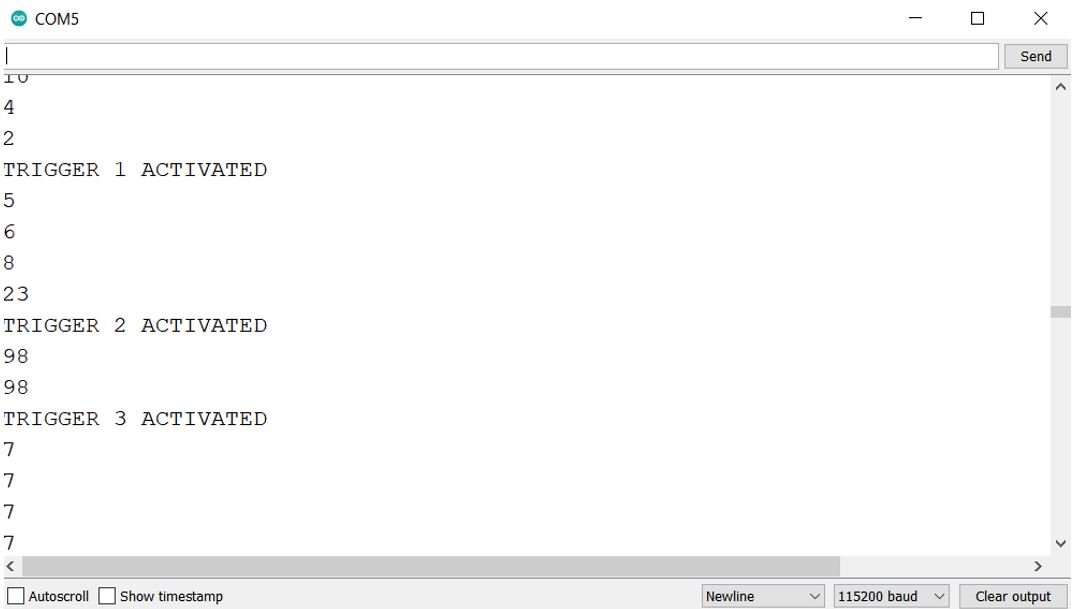

All 3 triggers will get activated. The IFTTT web service will generate an email alert.
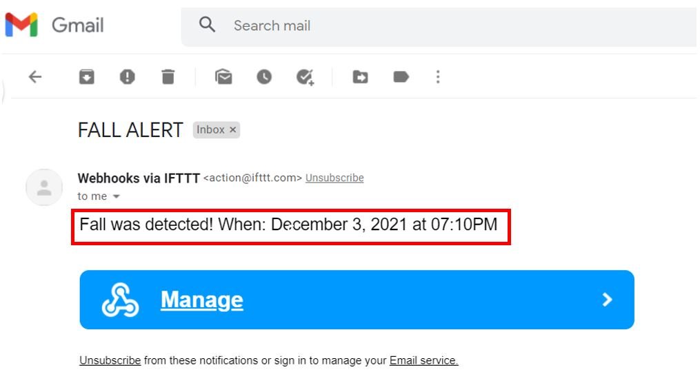
Go to your email account and open it. There you will be able to view the email notification from IFTTT regarding the fall detection and its exact date and time.
More ESP32 projects:
- ESP32 RGB LED Controller Web Server
- IoT Based Analog and Digital Clock using OLED and ESP32/ESP8266
- ESP32 DHT11 and DHT22 Web Server using Arduino IDE
- Internet Based Digital Clock using ESP32 and MAX7219 Dot Matrix Display
- ESP32 IoT Motion Detection Web Server with Email Alert
- IoT based Soil Moisture Monitoring System with ESP32 and Adafruit IO
- BME680 Web Server with ESP32 ( Arduino IDE)