In this user guide, we will learn about BMP180 barometric sensor and how to interface it with ESP8266 development board. The guide includes a brief introduction of the sensor with its pinout and a connection diagram with ESP8266. Additionally, we will show you two sketches where we will be able to access the temperature and pressure readings from this sensor and display them on the Serial Monitor as well as on an OLED.
BMP180 sensor can be used to measure temperature, pressure, and altitude. We can also measure pressure at sea level and real altitude with this sensor.
We have a similar guide with ESP32 and Arduino:
- Arduino with BMP180 Atmospheric Pressure and Temperature sensor
- ESP32 with BMP180 Atmospheric Pressure and Temperature sensor
BMP180 Introduction
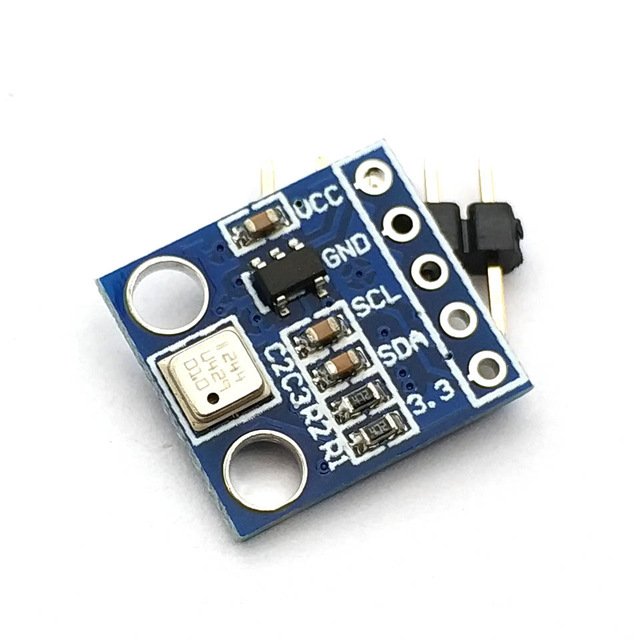
BMP 180 atmospheric pressure sensor is a type of sensor which is mainly used for measuring atmospheric pressure or biometric pressure. It is a high precision low cost sensing solution and specially designed for consumer applications such as weather forecast, sports devices ,GPS, computer peripherals, indoor navigation, hobby projects and vertical velocity indication etc. It can also be used as an altimeter because pressure is changed with altitude. Very easy to use and easy to solder on printed circuit board(PCB) as well as it has small size and consume less power. If it used as a temperature sensor then it is prefect sensor. It is easily available on market or online shop. A simple BMP180 atmospheric pressure sensor is shown below:
Features
- This digital pressure sensor is used to measure pressure of air in the range of 300-1100 hPa.
- Has a temperature measurement feature.
- Operates at wide range of voltages between 1.8 to 3.6 volts.
- It has very low noise and low power consumption of about 5µA at 1 sample / sec in standard mode.
- It can be interfaced with any microcontroller through I2C communication.
Pinout
BMP180 works on I2C communication protocol. It consists of four pins as shown in table below:
| Pins | Description |
| Vin ( Power supply pin ) | This is the power supply pin connected to 3.3V to 5V dc source |
| GND | This is the GND pin of power supply |
| SCL ( I2C clock pin ) | This is the serial clock pin and is used for clock pulse. Connect with SCL pin of any microcontroller |
| SDA (I2C data pin ) | This is the serial data pin and is used for serial communication. Connect with SDA pin of any microcontroller |
Recommended Reading: BMP 180 Atmospheric Pressure Sensor introduction
Interfacing BMP180 with ESP8266
We will require the following components for this project.
Required Components:
- ESP8266 development board
- BMP180 sensor
- Connecting Wires
Assemble the devices as shown in the schematic diagram below:
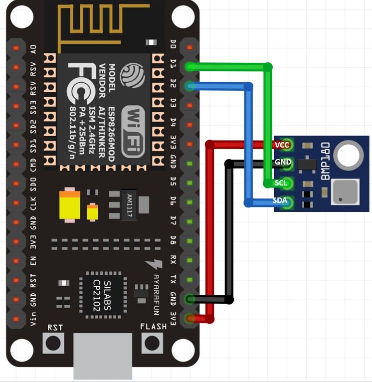
We will connect 4 pins of the BMP180 sensor with ESP8266. These include the VCC, GND, SCL and SDA pins. The VCC will be connected with the 3.3V pin from the ESP8266 board. GND of both the devices will be in common. The default SPI GPIO pins of ESP8266 are being used to connect with each of the remaining I2C terminals of the BMP180 module.
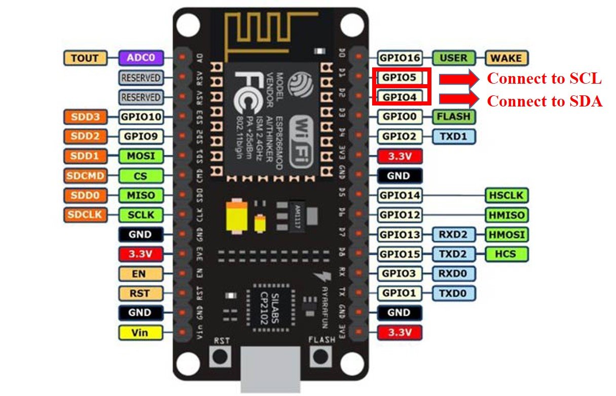
The figure below shows the default I2C pins of ESP8266.
- GPIO4 (D2) is the default SDA pin.
- GPIO5 (D1) is the default SCL pin.
The table below shows the connections between ESP8266 and BMP180 sensor:
| ESP8266 | BMP180 |
| GPIO4 (D2) | SDA |
| GPIO5 (D1) | SCL |
| GND | GND |
| 3.3V | VCC |
Now follow the connections between the two devices and connect them accordingly. We have used the same connections as specified above. All devices will have their grounds in common.
Installing BMP180 Library
We will use Arduino IDE to program our ESP8266 board. We have an Adafruit library for BMP180 which can be easily used to get the sensor readings. Now let’s see how to install this library in Arduino IDE.
To install the library, we will use the Arduino Library Manager. Open your Arduino IDE and go to Sketch > Include Libraries > Manage Libraries. Type ‘adafruit bmp180’ in the search bar and install the latest version of the library highlighted below. Notice that it is the ‘AdafruitBMP085 Library’ which is used for both BMP085 and BMP180.

ESP8266 Sketch: Obtaining BMP180 Sensor Readings
Open your Arduino IDE and go to File > New. A new file will open. Copy the code given below in that file and save it.
This code displays the temperature in degree Celsius, atmospheric pressure in Pa, sea level pressure in Pa, altitude and real altitude in meters in the Serial Monitor.
#include <Wire.h>
#include <Adafruit_BMP085.h>
#define seaLevelPressure_hPa 1013.25

Adafruit_BMP085 bmp;

void setup() {
  Serial.begin(115200);
  if (!bmp.begin()) {
  Serial.println("BMP180 Not Found. CHECK CIRCUIT!");
  while (1) {}
  }
}

void loop() {
    Serial.print("Temperature = ");
    Serial.print(bmp.readTemperature());
    Serial.println(" *C");

    Serial.print("Pressure = ");
    Serial.print(bmp.readPressure());
    Serial.println(" Pa");

    Serial.print("Pressure at sealevel (calculated) = ");
    Serial.print(bmp.readSealevelPressure());
    Serial.println(" Pa");

    Serial.print("Altitude = ");
    Serial.print(bmp.readAltitude());
    Serial.println(" meters");

    Serial.print("Real altitude = ");
    Serial.print(bmp.readAltitude(seaLevelPressure_hPa * 100));
    Serial.println(" meters");

    Serial.println();
    delay(1000);
}
How the Code Works?
We will include all the necessary libraries e.g. Wire and Adafruit_BMP085. Wire.h will be required as we are using I2C protocol to communicate between the BMP180 sensor and the ESP8266 board.
#include <Wire.h>
#include <Adafruit_BMP085.h>
Then, we will define the Adafruit_BMP085 object named ‘bmp’ by setting it on the default I2C GPIO pins of ESP8266.
Adafruit_BMP085 bmp;Additionally, we will define the sea level pressure in hPa.
#define seaLevelPressure_hPa 1013.25setup()
Inside the setup() function, we will start the serial connection at a baud rate of 115200. Then we will initialize the BMP180 sensor. If the connection between the module and the sensor is incorrect it will print that message on the serial monitor.
void setup() {
  Serial.begin(115200);
  if (!bmp.begin()) {
  Serial.println("BMP180 Not Found. CHECK CIRCUIT!");
  while (1) {}
  }
}
loop()
Inside the loop() function we will print the sensor readings acquired from the BMP180 sensor in the serial monitor after every second.
First, we will display the temperature reading in degree Celsius. We will use the bmp object on readTemperature() to access the temperature reading in degree Celsius.
Likewise, to access pressure, pressure at sea level, altitude and real altitude we will use the bmp object on readPressure(), readSealevelPressure(), readAltitude() and readAltitude(seaLevelPressure_hPa * 100) respectively.
void loop() {
    Serial.print("Temperature = ");
    Serial.print(bmp.readTemperature());
    Serial.println(" *C");

    Serial.print("Pressure = ");
    Serial.print(bmp.readPressure());
    Serial.println(" Pa");

    Serial.print("Pressure at sealevel (calculated) = ");
    Serial.print(bmp.readSealevelPressure());
    Serial.println(" Pa");

    Serial.print("Altitude = ");
    Serial.print(bmp.readAltitude());
    Serial.println(" meters");

    Serial.print("Real altitude = ");
    Serial.print(bmp.readAltitude(seaLevelPressure_hPa * 100));
    Serial.println(" meters");

    Serial.println();
    delay(1000);
}
Demonstration
Click on the upload button to upload the code to the ESP8266 development board.
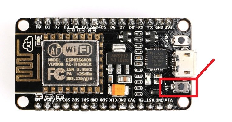
After you have uploaded your code to the development board, press its RST button.
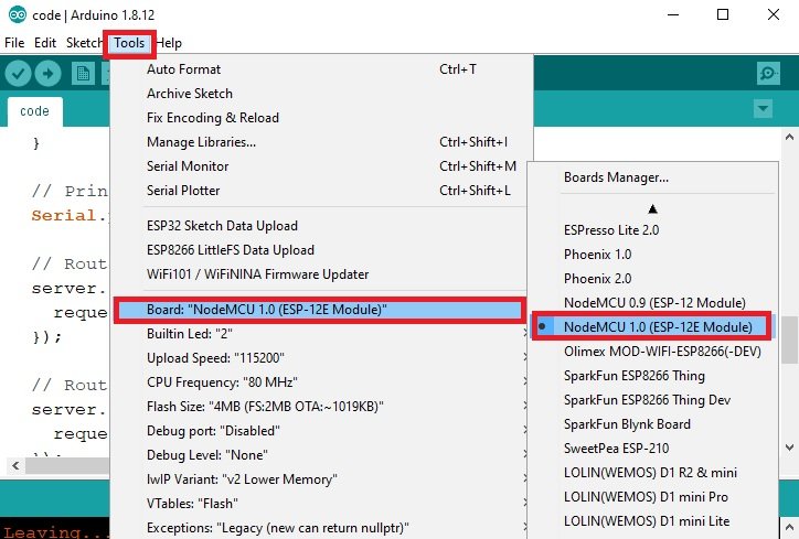
Now open the serial monitor in Arduino IDE, you will see all the sensor readings getting displayed after every second.

ESP8266 Display BMP180 Temperature and Pressure Readings on OLED
In this section, we will see how to display the temperature and pressure readings of BMP180 on a 0.96 SSD1306 OLED display using Arduino IDE and ESP8266 board.
Installing SSD1306 OLED Library in Arduino IDE
To use the OLED display in our project, we have to install the Adafruit SSD1306 OLED library in Arduino IDE. Follow the steps below to successfully install it.
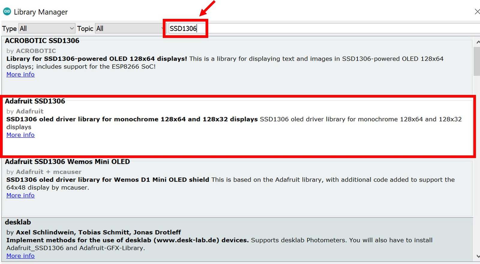
Open Arduino IDE and click on Sketch > Library > Manage Libraries. Type ‘SSD1306’ in the search tab and install the Adafruit SSD1306 OLED library.
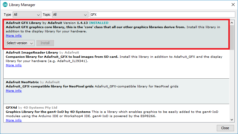
We will also require the Adafruit GFX library which is a dependency for SSD1306. Type ‘Adafruit GFX’ in the search tab and install it as well.
You may like this in-depth guide on OLED interfacing with ESP8266:
- OLED Display Interfacing with ESP8266 NodeMCU – Display Text, Draw shapes and Images
Schematic – OLED with ESP8266 and BMP180
This section shows how to connect an ESP8266 board with BMP180 and an OLED display. Follow the connections as described in the two tables below.
The table below show the terminals of the three devices which should be connected together.
| OLED Display | ESP8266 | BMP180 |
| VCC | 3.3V | 3.3V |
| GND | GND | GND |
| SCL | GPIO5 (D1) | SCL |
| SDA | GPIO4 (D2) | SDA |
Assemble the circuit as shown in the schematic diagram below:

We will connect the VCC terminal of the OLED display with 3.3V which will be in common with the ESP8266 board and BMP180 VCC. SCL of the display will be connected with the SCL pin of the ESP8266 board and the SDA of the display will be connected with the SDA of the ESP8266 board.
ESP8266 Sketch to Display BMP180 Readings on OLED
Copy the following code to your Arduino IDE and upload it to the ESP8266 board after assembling the above circuit diagram.
#include <Wire.h>
#include <Adafruit_BMP085.h>
#include <Adafruit_GFX.h>
#include <Adafruit_SSD1306.h>

#define seaLevelPressure_hPa 1013.25

Adafruit_BMP085 bmp;
Adafruit_SSD1306 display = Adafruit_SSD1306(128, 64, &Wire, -1);

void setup() {
  Serial.begin(115200);
  if (!bmp.begin()) {
  Serial.println("BMP180 Not Found. CHECK CIRCUIT!");
  while (1) {}
  }
  display.begin(SSD1306_SWITCHCAPVCC, 0x3C);
if(!display.begin(SSD1306_SWITCHCAPVCC, 0x3C)) {
  Serial.println(F("SSD1306 allocation failed"));
  for(;;);
}
  delay(2000);
display.clearDisplay();
display.setTextColor(WHITE);
}

void loop() {
    Serial.print("Temperature = ");
    Serial.print(bmp.readTemperature());
    Serial.println(" *C");

    Serial.print("Pressure = ");
    Serial.print(bmp.readPressure());
    Serial.println(" Pa");
    Serial.println();

  display.setTextSize(1);
  display.setCursor(0,0);
  display.print("Temperature: ");
  display.setTextSize(2);
  display.setCursor(0,10);
  display.print(bmp.readTemperature());
  display.print(" ");
  display.setTextSize(1);
  display.cp437(true);
  display.write(167);
  display.setTextSize(2);
  display.print("C");

  display.setTextSize(1);
  display.setCursor(0, 35);
  display.print("Pressure: ");
  display.setTextSize(2);
  display.setCursor(0, 45);
  display.print(bmp.readPressure());
  display.print(" Pa");

  display.display();
  delay(1000);
  display.clearDisplay();
}
How the Code Works?
We will first include the required libraries for BMP180 as well as the OLED display which we just installed before.
#include <Wire.h>
#include <Adafruit_BMP085.h>
#include <Adafruit_GFX.h>
#include <Adafruit_SSD1306.h>
Then, we will define the Adafruit_BMP085 object named ‘bmp’ by setting it on the default I2C GPIO pins of ESP8266.
Adafruit_BMP085 bmp;Now, we will create an object named display which will be handling the OLED display and specifying the width, height, I2C instance (&Wire), and -1 as parameters inside it.’ -1′ specifies that the OLED display which we are using does not have a RESET pin. If you are using the RESET pin then specify the GPIO through which you are connecting it with your development board.
Adafruit_SSD1306 display = Adafruit_SSD1306(128, 64, &Wire, -1);setup()
Inside the setup() function, we will initialize the serial communication with the baud rate of 115200
Serial.begin(115200);Then we will initialize the BMP180 sensor. If the connection between the module and the sensor is incorrect it will print that message on the serial monitor.
  if (!bmp.begin()) {
  Serial.println("BMP180 Not Found. CHECK CIRCUIT!");
  while (1) {}
  }
We will also initialize the OLED display by using display.begin(). Make sure you specify the correct address of your display. In our case, it is 0X3C.
display.begin(SSD1306_SWITCHCAPVCC, 0x3C);

if(!display.begin(SSD1306_SWITCHCAPVCC, 0x3C)) {
  Serial.println(F("SSD1306 allocation failed"));
  for(;;);
}
  delay(2000);
Then, we will clear the buffer by using clearDisplay() on the Adafruit_SSD1306 object. Additionally, we will set the colour of the text as white.
display.clearDisplay();
display.setTextColor(WHITE);
loop()
Inside the loop() function, we will first display the temperature by using readTemperature() method on the bmp instance and readPressure() method on the bmp instance. These will get printed in the serial monitor along with their units after a delay of every 1 second.
    Serial.print("Temperature = ");
    Serial.print(bmp.readTemperature());
    Serial.println(" *C");

    Serial.print("Pressure = ");
    Serial.print(bmp.readPressure());
    Serial.println(" Pa");
    Serial.println();
The setTextSize() function is used to set the size of font. We used low size for simple text such as “Temperature” and high size font to display actual readings. The setCursor() method defined where we want to display our text on 128×64 OLED. Finally, the print() functions write the text on the defined position. We will display the updated temperature reading and pressure reading along with their units on the OLED screen after every second.
  display.setTextSize(1);
  display.setCursor(0,0);
  display.print("Temperature: ");
  display.setTextSize(2);
  display.setCursor(0,10);
  display.print(bmp.readTemperature());
  display.print(" ");
  display.setTextSize(1);
  display.cp437(true);
  display.write(167);
  display.setTextSize(2);
  display.print("C");

  display.setTextSize(1);
  display.setCursor(0, 35);
  display.print("Pressure: ");
  display.setTextSize(2);
  display.setCursor(0, 45);
  display.print(bmp.readPressure());
  display.print(" Pa");

  display.display();
  delay(1000);
  display.clearDisplay();
Demonstration
Click on the upload button to upload the code to the ESP8266 development board.
After you have uploaded your code to the development board, press its RST button.

Once the code is uploaded to your board, the OLED will start displaying the temperature and pressure readings after every second.

You may also like to read:
- Display Sensor Readings in Gauges with ESP8266 Web Server
- MAX30102 Pulse Oximeter and Heart Rate Sensor with ESP8266
- MAX30100 Pulse Oximeter and Heart Rate Sensor with ESP8266
- MLX90614 Non-contact Infrared Temperature Sensor with ESP8266
- K-Type Thermocouple MAX6675 Amplifier with ESP8266 NodeMCU
- NEO-6M GPS Module with ESP8266 NodeMCU and Track Location on Google Maps
The project with the Esp8266 micro controller + BMP180 sensor + OLED128x64 display components was implemented by me myself. While building the project, I was thinking about how this project could be further developed in the form of expanding it with 2 nRF24L01 tip. RF modules and 1 BMP180 sensor, how to implement this project so that both external and internal sensor data is displayed on this OLED display.
Great Tutorial, Both Progs worked first time. I even had a different Oled display, 128 x 32. It still worked although the words Temperature and Pressure were compressed The Values however were excellent. I expected to have only the Temperature displayed and was ready to change the coding a little, anyway thankyou. Its great when these little project/demos work, so much time wasted on ones that did not in the past. I hope to use this as a baseline for an esp8266 with quite a few more I2C sensors attached.