In this guide, we will show you how to log sensor readings to Firebase Realtime database along with current timestamps. We will use ESP8266 NodeMCU along with BME280 sensor for this project. Firstly, we will create a Firebase project to log temperature, pressure, and humidity readings along with timestamps. The Firebase project data will be secured by enabling email/password authentication as well. Hence, the sensor readings will be securely logged on the Firebase Realtime database by an authorized user only.
We have a similar guide with ESP32:
ESP8266 NodeMCU Data Logging Firebase Project Overview
The aim of this project is to log sensor readings acquired from BME280 sensor to the Firebase Realtime database along with the current epoch time. The current epoch time will be acquired from an NTP server. In the data logger application, Epoch timestamp is useful to log values along with timestamps. Epoch time is also known as Unix epoch, Unix time, POSIX time, or Unix timestamp.
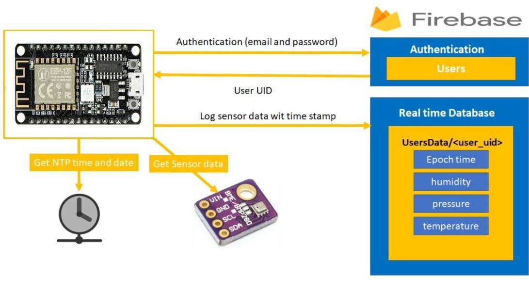
Below we will list down the whole project process:
- Firstly, the ESP8266 board secures a connection with Goggle Firebase through an authorized email/password.
- After a successful connection has been established, the ESP8266 board receives the user UID that will be used to log sensor data to the Firebase database.
- BME280 is used to measure temperature in Celsius/Fahrenheit, humidity, and Pressure. The ESP8266 board acquires these three sensor readings along with the current epoch time from the NTP server. Recommended Reading: Getting Epoch/Unix time with ESP8266 NodeMCU through NTP server using Arduino IDE
- This data (temperature, humidity, pressure and timestamp) is sent to the Firebase Realtime Database after every 5 minutes.
You can read about firebase authentication here:
Connecting BME280 sensor with ESP8266 NodeMCU
The connection of BME280 with the ESP8266 board is very easy. We have to connect the VCC terminal with 3.3V, ground with the ground (common ground), SCL of the sensor with SCL of the module, and SDA of the sensor with the SDA pin of the ESP8266 module.
The I2C pin in ESP8266 for SDA is GPIO4 (D2) and for SCL is GPIO5 (D1)
Required Components
We will need the following components to connect our ESP8266 board with the BME280 sensor.
- ESP8266 board
- BME280 Sensor
- Connecting Wires
- Breadboard
Schematic Diagram
Connect the ESP8266 device with BME280 as shown in the schematic diagram below:
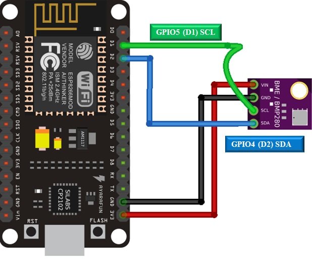
Vin is connected with a 3.3V pin on the module and both the ESP8266 board and the sensor is commonly grounded.
In some BME280 sensors, the SCK terminal means the SCL pin and is connected with its respective GPIO pin on the ESP82266 board. Likewise, the SDI terminal means the SDA pin and is connected with its respective GPIO pin on the board.
You may like to read these BME280 tutorials:
- BME280 Web Server with ESP8266 NodeMCU (Arduino IDE)
- Telegram ESP32/ESP8266: Display BME280 sensor readings using Arduino IDE
- BME280 with ESP8266 NodeMCU – Display Values on OLED ( Arduino IDE)
- MicroPython: BME280 Web Server with ESP32/ESP8266
Google Firebase Introduction
Google Firebase is an application development software created by Google. It can be used with any android/IOS application, IoT sensors and web services to create and alter the data obtained from them. It is a helpful software for building mobile/web applications easily and interactively. Paid services include a Real-time database, firebase storage, hosting and test lab. However, you can use Analytics for advanced messaging for free although you will have to create an account before accessing it.
One of the significant attributes of this software is that it is beginner friendly. It is very simple to connect your application to Google Firebase. You have to follow each step carefully. If you have any difficulty or want to access further information, take a look at the official Google Firebase Documentation.
Setting up Google Firebase Console
Before proceeding with the project let us understand the steps which have to be followed to successfully connect with the Google Firebase application.
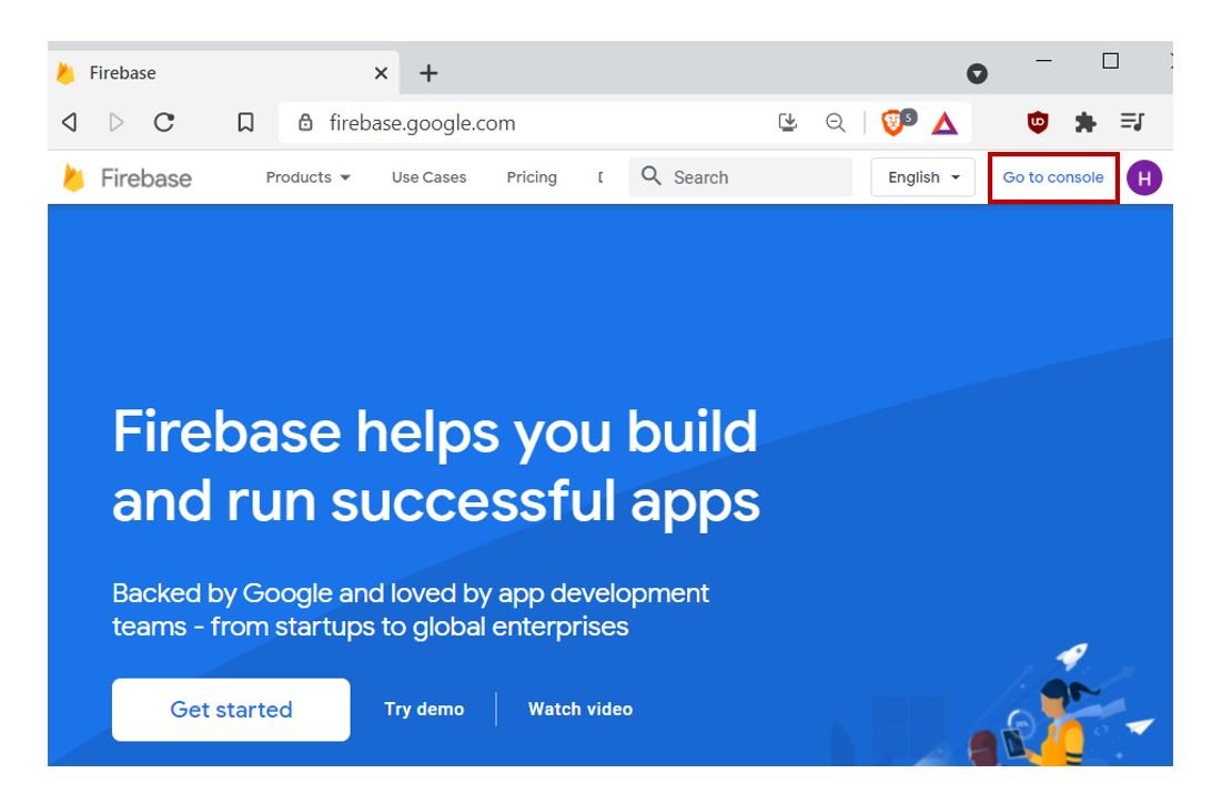
Firstly, type https://firebase.google.com/ in your browser search tab and press enter.
This will open the Firebase main page. Click ‘Go to Console’ as highlighted in the red rectangular box.
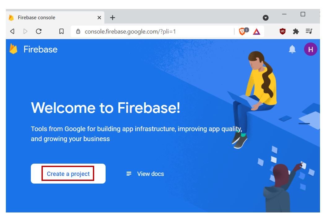
You will be redirected to a new web page with the welcome message. Click the button ‘Create a Project’ as shown below.
The following page opens up.
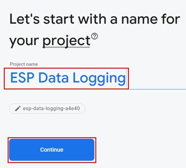
Step 1: Write the name of your project. Remember to tick the Firebase term agreement. Now click ‘Continue.’
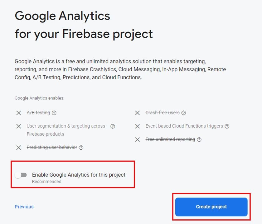
Step 2: There is no need to enable ‘Google analytics for this project’ as we do not require it. Click ‘Create project’ to proceed further.
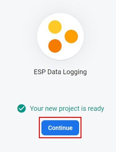
After a few moments, your project will be created.
Click ‘Continue’
Setting Authentication Methods
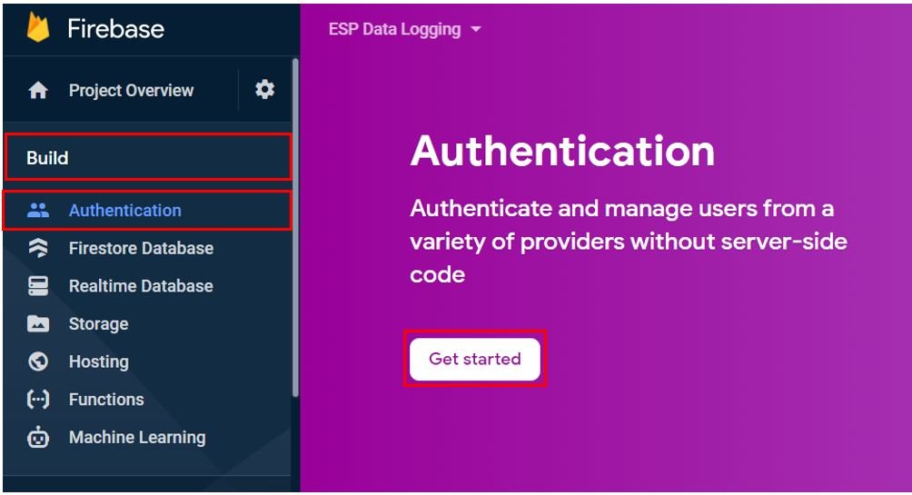
You will be redirected to the page of your newly created project. Go to Build > Authentication.
Click ‘Get Started’ to start the authentication process.
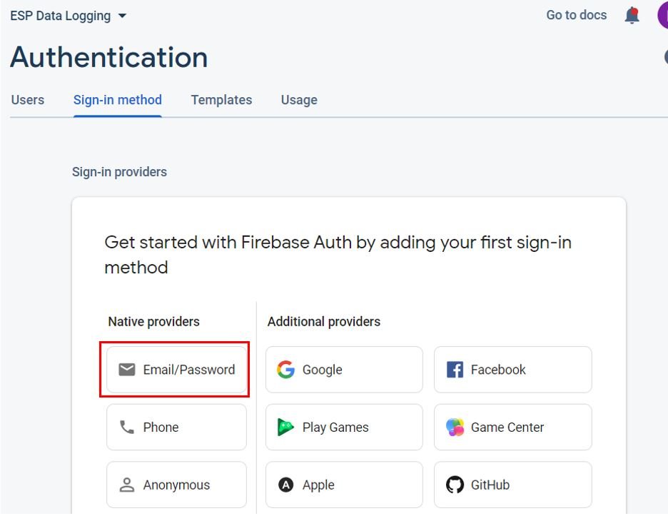
The following page will appear. Here we will head over to ‘Email/Password’ option as the sign-in method.
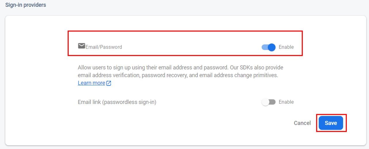
Enable the ‘Email/Password’ option by sliding the slider to the right. Then save the settings.
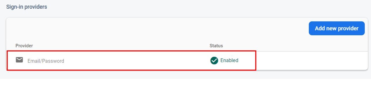
This authenitcation method will now be enabled as seen below:
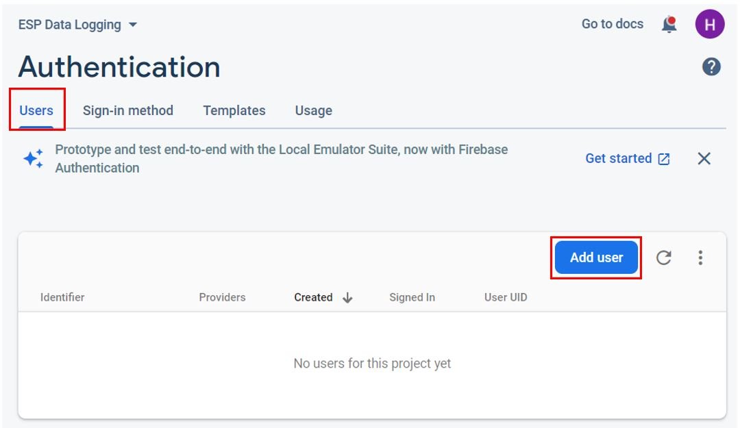
Now, you will have to provide the Email/Password of the user that will have access to the firebase project. First, click ‘Users’ in the tab and then head over to ‘Add user.’
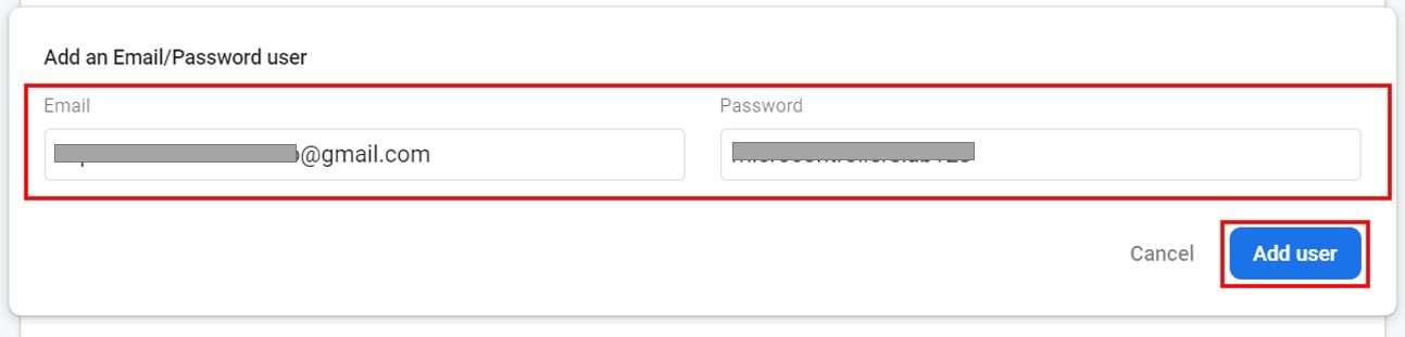
Specify the email and password of the user. Then click ‘Add user.’
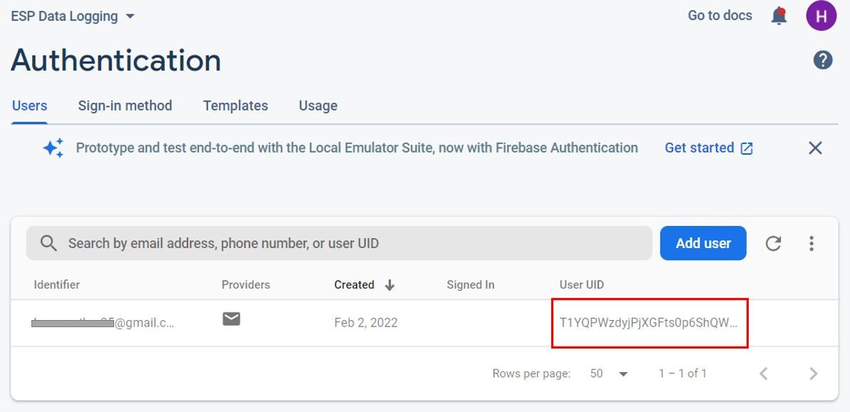
After adding the user, you will be able to view the email, date created and user UID associated with the user you just authorized. You may notice that the ‘Signed in’ section is empty. This is because this particular user has not yet signed in to the Firebase project.
Obtaining API Key
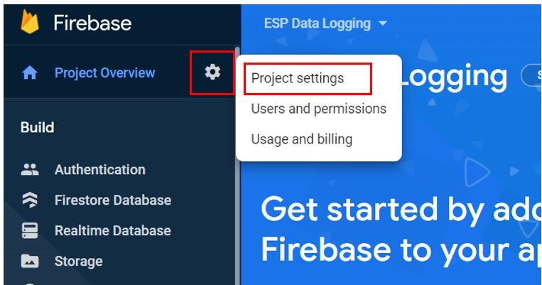
Go to the settings icon and click ‘Project Settings’.
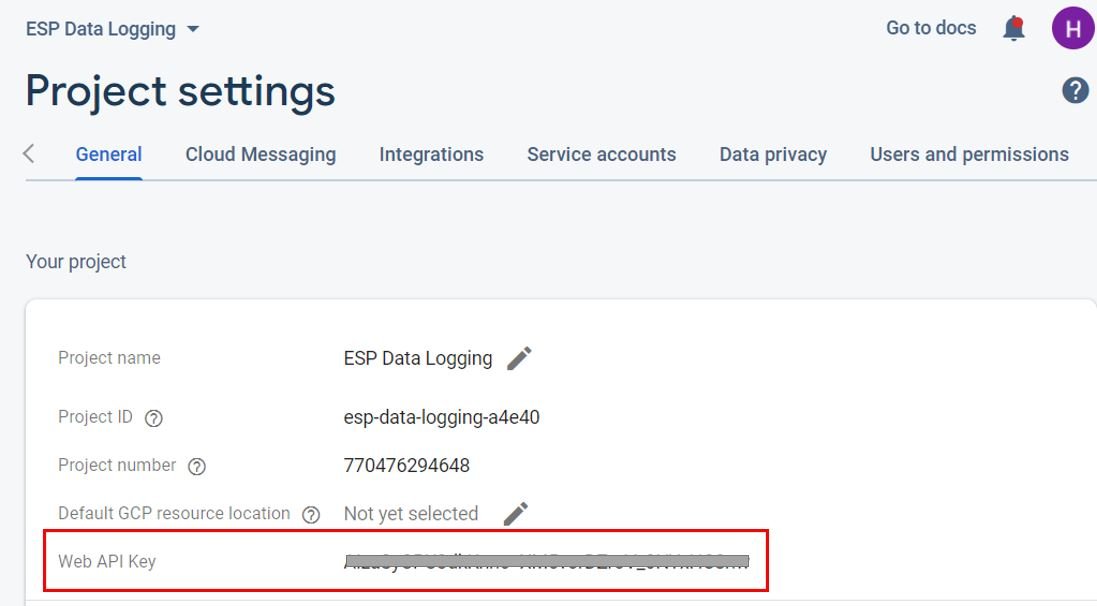
Under the project settings, you will be able to view the API key as highlighted below. This is unique for your project. Keep it safe. We will need it while programming our ESP8266 NodeMCU board.
Realtime Database
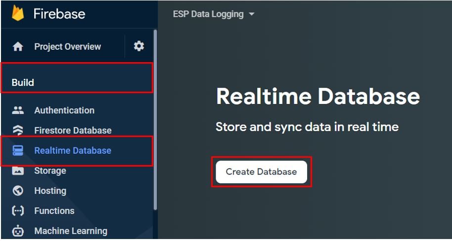
Under the Build tab go to ‘Realtime Database.’ Then click ‘Create Database.’
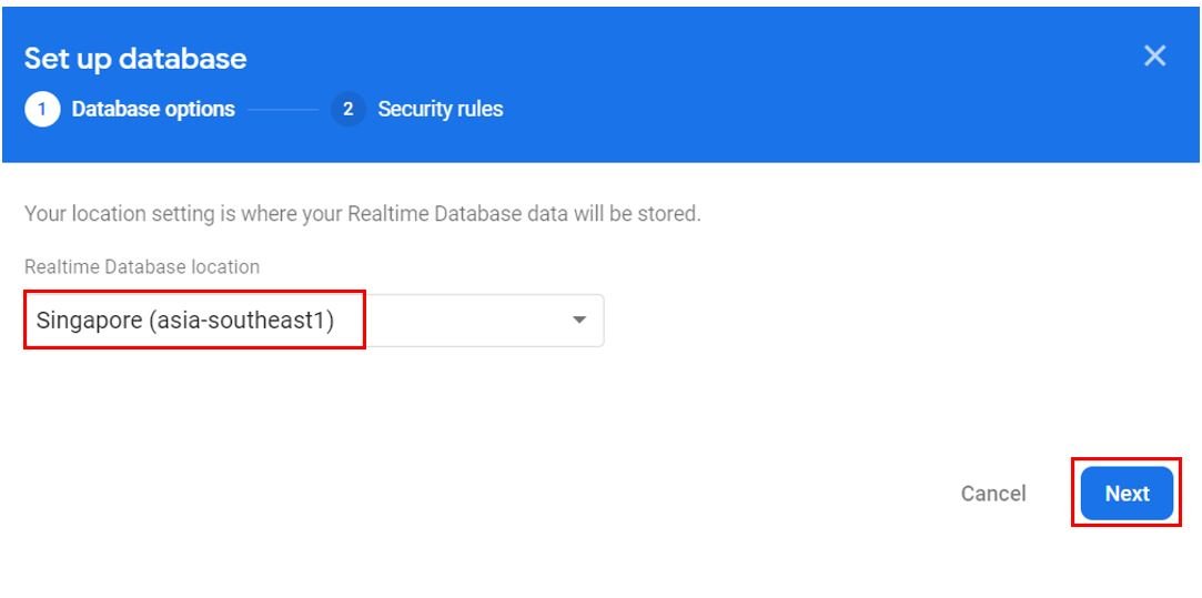
Specify the Realtime database location and click Next.
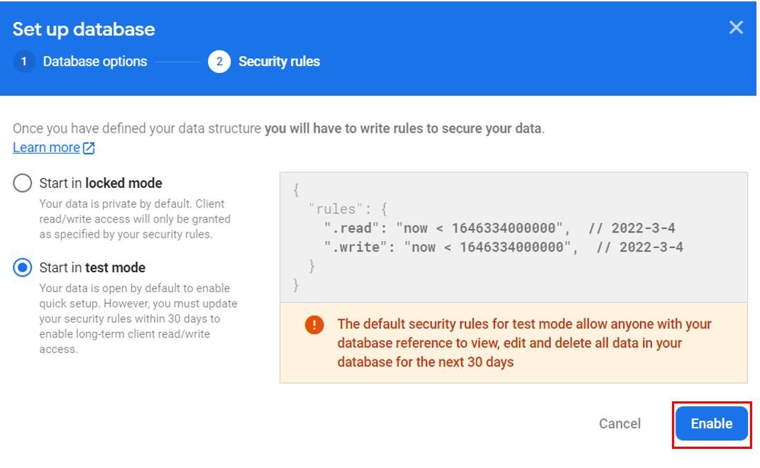
For security rules, start in test mode for the time being. We will edit the rules shortly. Now click ‘Enable.’
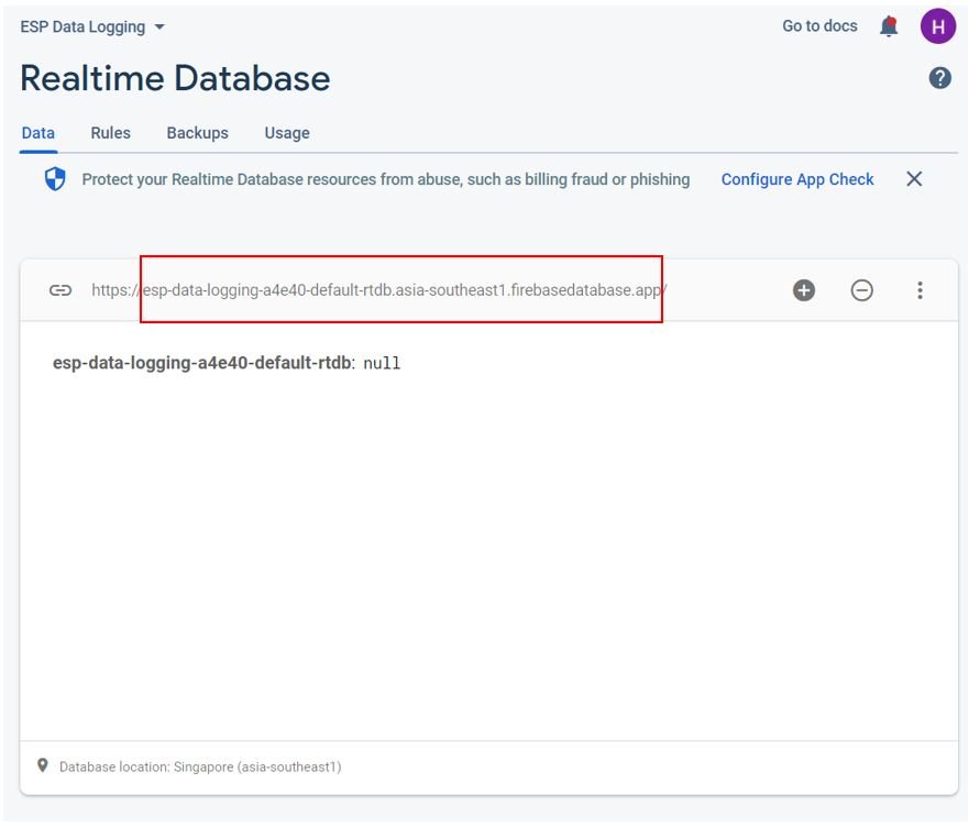
Your database settings are now completed. Now our Realtime database will be created. You can view the database URL as shown below. Save it as we will require it while programming our ESP8266 board.
Now head over to the ‘Rules’ tab and then ‘Edit rules’. Copy the rules that we have shown below and then click the ‘Publish’ button.
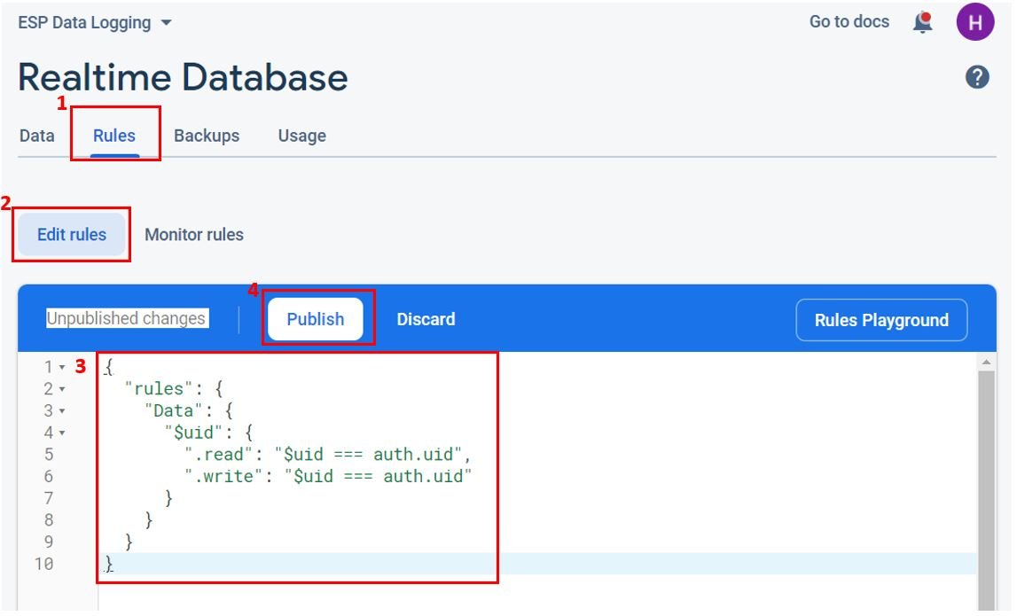
These rules will secure our data. We have stated that the node ‘Data’ consists of another node that will be the user UID. Only authenticated users will have access to their own node. Therefore an authenticated user will be only able to (read/write) to a node matching its UID. The user with UID ‘x’ will be able to read/write data under the node: Data/x.
Setting up Arduino IDE
We will use Arduino IDE to program our ESP8266 development board. Thus, you should have the latest version of Arduino IDE. Additionally, you also need to install the plugin for the respective board which you will use.
If your IDE does not have the plugin installed you can visit the link below:
Installing BME280 Libraries
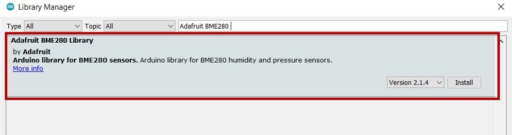
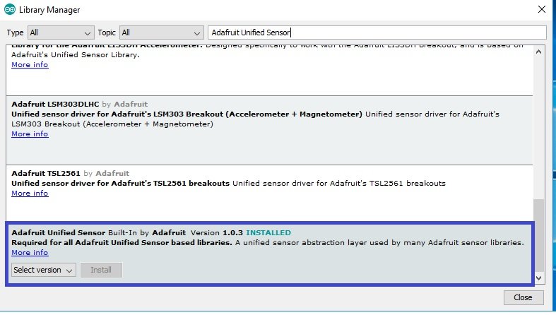
As we are connecting the BME280 sensor with ESP8266 so we will have to install BME280 libraries to our module. We will require two libraries for this project:
- Adafruit_BME280 library
- Adafruit_Sensor library
We will use the Library Manager in our Arduino IDE to install the latest versions of the libraries. Open your Arduino IDE and go to Sketch > Include Libraries > Manage Libraries. Type each library name in the search bar and install them both.
Installing Google Firebase ESP Client Library
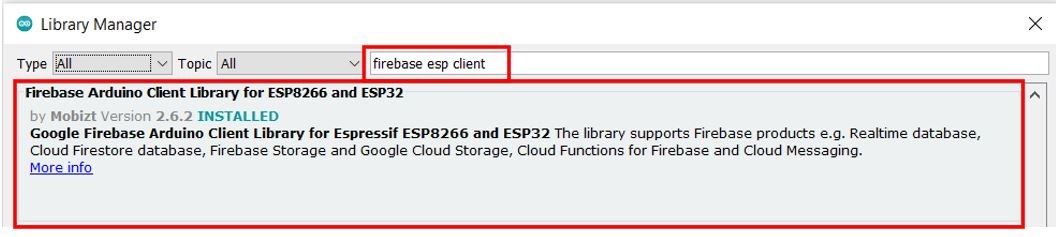
We will require the firebase ESP client library for this project. This library is compatible with both ESP32 and ESP8266 development boards. We will use the Library Manager in Arduino IDE to install it succefuuly.
Open Arduino IDE and click on Sketch > Library > Manage Libraries. Type ‘Firebase ESP Client’ in the search tab and install the latest version of Firebase Arduino Client Library for ESP8266 and ESP32 that is shown below.
After installation of the library, restart your IDE.
Arduino Sketch ESP8266 Real-time Data Logging
Open your Arduino IDE and go to File > New to open a new file.
Copy the code given below in that file. You need to enter your network credentials. You also have to provide your web API key and database URL which were saved previously. Moreover, you will have to specify the email and password that you used in Firebase authentication to authorize the user.
#include <Arduino.h>
#include <ESP8266WiFi.h>
#include <Firebase_ESP_Client.h>
#include <Wire.h>
#include <Adafruit_Sensor.h>
#include <Adafruit_BME280.h>
#include <NTPClient.h>
#include <WiFiUdp.h>
#include "addons/TokenHelper.h"
#include "addons/RTDBHelper.h"
//Enter your network credentials
const char* ssid = "YOUR_SSID";
const char* password = "YOUR_PASSWORD";
//Enter Firebase web API Key
#define API_KEY "AIzaSyCPU3dkKnnc--XM5vorDZroV_0NYxH****"
// Enter Authorized Email and Password
#define USER_EMAIL "WRITE_AUTHORIZED_EMAIL"
#define USER_PASSWORD "WRITE_AUTHORIZED_PASSWORD"
// Enter Realtime Database URL
#define DATABASE_URL "WRITE_YOUR_REALTIME_DATABASE_URL"
FirebaseData Firebase_dataObject;
FirebaseAuth authentication;
FirebaseConfig config;
String UID;
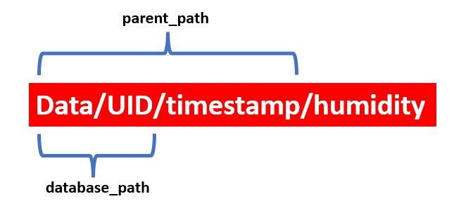
// Database main path
String database_path;
String temperature_path = "/temperature";
String humidity_path = "/humidity";
String pressure_path = "/pressure";
String time_path = "/epoch_time";
//Updated in every loop
String parent_path;
int epoch_time;
FirebaseJson json;
// Define NTP Client to get time
WiFiUDP ntpUDP;
NTPClient timeClient(ntpUDP, "pool.ntp.org");
Adafruit_BME280 bme;
float temperature;
float humidity;
float pressure;
//send new readings every 5 minutes
unsigned long previous_time = 0;
unsigned long Delay = 300000;
//get current epoch time
unsigned long Get_Epoch_Time() {
timeClient.update();
unsigned long now = timeClient.getEpochTime();
return now;
}
void setup(){
Serial.begin(115200);
if (!bme.begin(0x76)) {
Serial.println("Could not find BME280 sensor. Check Connections!");
while (1);
}
WiFi.begin(ssid, password);
Serial.print("Connecting to WiFi ..");
while (WiFi.status() != WL_CONNECTED) {
Serial.print('.');
delay(1000);
}
Serial.println(WiFi.localIP());
Serial.println();
timeClient.begin();
config.api_key = API_KEY;
authentication.user.email = USER_EMAIL;
authentication.user.password = USER_PASSWORD;
config.database_url = DATABASE_URL;
Firebase.reconnectWiFi(true);
Firebase_dataObject.setResponseSize(4096);
config.token_status_callback = tokenStatusCallback;
config.max_token_generation_retry = 5;
Firebase.begin(&config, &authentication);
Serial.println("Getting User UID...");
while ((authentication.token.uid) == "") {
Serial.print('.');
delay(1000);
}
UID = authentication.token.uid.c_str();
Serial.print("User UID: ");
Serial.println(UID);
database_path = "/Data/" + UID + "/BME280 Readings";
}
void loop(){
if (Firebase.ready() && (millis() - previous_time > Delay || previous_time == 0))
{
previous_time = millis();
epoch_time = Get_Epoch_Time();
Serial.print ("time: ");
Serial.println (epoch_time);
parent_path= database_path + "/" + String(epoch_time);
json.set(temperature_path.c_str(), String(bme.readTemperature()));
json.set(humidity_path.c_str(), String(bme.readHumidity()));
json.set(pressure_path.c_str(), String(bme.readPressure()/100.0F));
json.set(time_path, String(epoch_time));
Serial.printf("Set json...%s\n",Firebase.RTDB.setJSON(&Firebase_dataObject, parent_path.c_str(), &json) ? "ok" : Firebase_dataObject.errorReason().c_str());
}
}
How the Code Works?
We will start off by including all the necessary libraries required for this project.
#include <Arduino.h>
#include <ESP8266WiFi.h>
#include <Firebase_ESP_Client.h>
#include <Wire.h>
#include <Adafruit_Sensor.h>
#include <Adafruit_BME280.h>
#include <NTPClient.h>
#include <WiFiUdp.h>
#include "addons/TokenHelper.h"
#include "addons/RTDBHelper.h"
Next, we will create two global variables, one for the SSID and another for the password. These will hold our network credentials which will be used to connect to our wireless router. Replace both of them with your network credentials to ensure a successful connection.
//Enter your network credentials
const char* ssid = "YOUR_SSID";
const char* password = "YOUR_PASSWORD";
Firebase Credentials
Next, we will define the Google firebase web API key which we accessed and saved previously
//Enter Firebase web API Key
#define API_KEY "AIzaSyCPU3dkKnnc--XM5vorDZroV_0NYxH****"
The next step is to specify the user email and password that we used while authorizing the user in our firebase project. Both of these should correspond to the ones you saved while adding the user.
// Enter Authorized Email and Password
#define USER_EMAIL "WRITE_AUTHORIZED_EMAIL"
#define USER_PASSWORD "WRITE_AUTHORIZED_PASSWORD"
Now enter the Realtime database URL that we previously acquired after creating our Realtime database. In our case the database URL is “esp-data-logging-a4e40-default-rtdb.asia-southeast1.firebasedatabase.app”
// Enter Realtime Database URL
#define DATABASE_URL "WRITE_YOUR_REALTIME_DATABASE_URL"
Next, we will create some objects for some firebase functionalities: data, authentication and configuration.
FirebaseData Firebase_dataObject;
FirebaseAuth authentication;
FirebaseConfig config;
Data Storage Variables
The string variable UID will save the user UID.
String UID;Next, we will create several string variables for the paths. The ‘database_path’ is the main path that will be updated with the user UID. Next, we have the paths for the sensor readings including temperature, humidity and pressure and the path of the current epoch time. The ‘parent_path’ is the path that will change after every loop with the new timestamp.
String database_path;  //main path

String temperature_path = "/temperature";
String humidity_path = "/humidity";
String pressure_path = "/pressure";
String time_path = "/epoch_time";

//Updated in every loop
String parent_path;
The integer variable ‘epoch_time’ will save the current epoch time acquired through the NTP server.
int epoch_time;Next we will create a FirebaseJson object called ‘json’. This will be used to send sensor data along with the current epoch time to the Realtime database easily.
FirebaseJson json;We will define the NTP client ‘pool.ntp.org’ to access the epoch time.
WiFiUDP ntpUDP;
NTPClient timeClient(ntpUDP, "pool.ntp.org");
BME280
Then, we will define the Adafruit_BME280 object named bme by setting it on the default I2C GPIO pins of ESP8266. Additionally, we will declare variables to hold BME280 sensor readings such as temperature, pressure, and humidity. These are declared as floating types because we will be dealing with numerical values which could have floating decimal points. In other words, the values returned by BME280 sensor are floating point values.
Adafruit_BME280 bme;
float temperature;
float humidity;
float pressure;
Here, we define two variable previous_time and Delay. We will include a delay of 5 minutes (300000ms) before sending the new readings. The updating time is being stored in the variable ‘Delay.’
//send new readings every 5 minutes
unsigned long previous_time = 0;
unsigned long Delay = 300000;
Get_Epoch_Time()
To get epoch/Unix time, we create the Get_Epoch_Time() function which will return the current epoch time whenever a request will be made to the server. This section of code shows the function and how it returns the time.
//get current epoch time
unsigned long Get_Epoch_Time() {
  timeClient.update();
  unsigned long now = timeClient.getEpochTime();
  return now;
}
setup()
In the setup() function, initiate the serial communication with a baud rate of 115200.
Serial.begin(115200);The following lines will initialize the BME280 sensor. In case of failure a relevant message will be printed on the Serial Monitor.
    if (!bme.begin(0x76)) {
    Serial.println("Could not find BME280 sensor. Check Connections!");
    while (1);
  }
The following section of code will connect our ESP8266 board with the local network whose network credentials we already specified above. We will use the WiFi.begin() function. The arguments will be the SSID and the password which we defined earlier in the code. After the connection will be established, the IP address of the ESP8266 board will get printed on the serial monitor.
WiFi.begin(ssid, password);
  Serial.print("Connecting to WiFi ..");
  while (WiFi.status() != WL_CONNECTED) {
    Serial.print('.');
    delay(1000);
  }
  Serial.println(WiFi.localIP());
  Serial.println();
We will also initialize the NTP client through the following line:
timeClient.begin();Now, first we will use the firebase data object we created for configuration and set the API key as well as the database URL. Then we will specify the user email and password to the firebase authentication object.
  config.api_key = API_KEY;
  authentication.user.email = USER_EMAIL;
  authentication.user.password = USER_PASSWORD;
  config.database_url = DATABASE_URL;
The following lines of code will be used to set the call-back function for long running token generation task. These will be set to the Firebase configuration object as well.
  config.token_status_callback = tokenStatusCallback;
  config.max_token_generation_retry = 5;
Using Firebase.begin() on the configuration and authentication paths, we will initialize the firebase library connection.
Firebase.begin(&config, &authentication);
In the following lines of code, we will retrieve the user UID
 Serial.println("Getting User UID...");
  while ((authentication.token.uid) == "") {
    Serial.print('.');
    delay(1000);
  }
  UID = authentication.token.uid.c_str();
  Serial.print("User UID: ");
  Serial.println(UID);
Moreover, the database_path will be set as follows: It consists of Data followed by the user UID and followed by BME280 Readings.
database_path = "/Data/" + UID + "/BME280 Readings";loop()
Inside the loop() function, we will obtain the current epoch time after connecting with Firebase and after every 5 minutes. This epoch time will get printed in the serial monitor.
Then we will update the parent_path with the current epoch_time value. Using json.set() we will update all the sensor readings and the timestamp with the current values. The first argument is the path and the second argument is the value.
Moreover, we will call Firebase.RTDB.setJSON(&Firebase_dataObject, parent_path.c_str(), &json) to add the new data to the parent path.
void loop(){
  if (Firebase.ready() && (millis() - previous_time > Delay || previous_time == 0)){
    previous_time = millis();

    epoch_time = Get_Epoch_Time();
    Serial.print ("time: ");
    Serial.println (epoch_time);

    parent_path= database_path + "/" + String(epoch_time);

    json.set(temperature_path.c_str(), String(bme.readTemperature()));
    json.set(humidity_path.c_str(), String(bme.readHumidity()));
    json.set(pressure_path.c_str(), String(bme.readPressure()/100.0F));
    json.set(time_path, String(epoch_time));
    Serial.printf("Set json... %s\n", Firebase.RTDB.setJSON(&Firebase_dataObject, parent_path.c_str(), &json) ? "ok" : Firebase_dataObject.errorReason().c_str());
  }
}
Demonstration
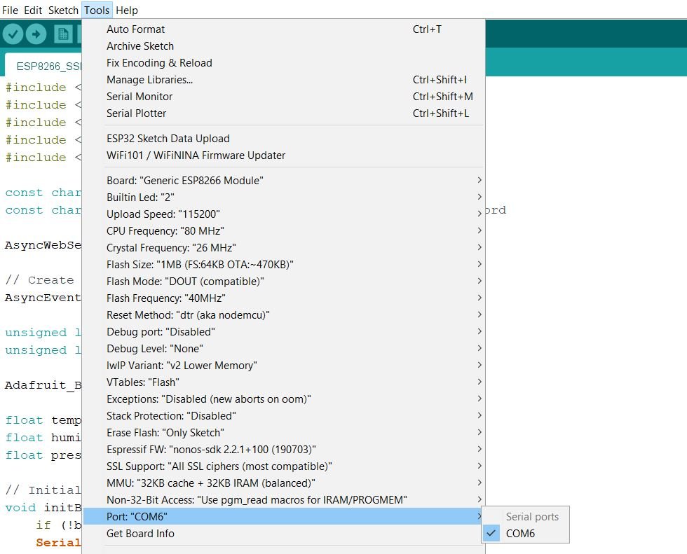
Choose the correct board and COM port before uploading your code to the board. Go to Tools > Board and select NodeMCU1.0

Next, go to Tools > Port and select the appropriate port through which your board is connected.
Click on the upload button to upload the code to your ESP8266 development board.
After you have uploaded your code to the development board, press its RST button.

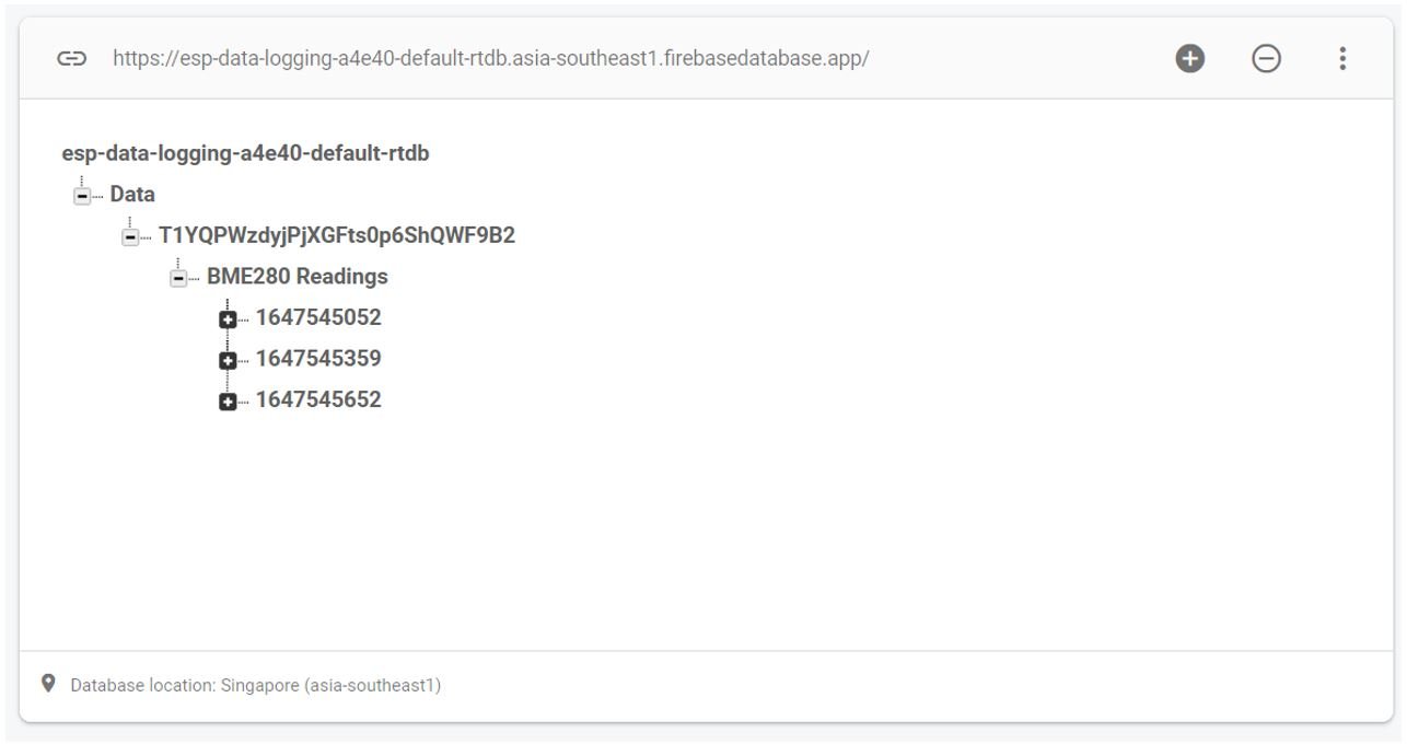
In your Arduino IDE, open up the serial monitor and you will be able to see the status of your WIFI connection and the IP address of your ESP8266 module. The first readings will be sent to your Firebase Realtime Database. Go to your Realtime Database in Firebase console. Here you will view all the data.
You can see that we have the Data followed by the user UID, then BME280 Readings. Under that we have timestamps showing the current epoch time. This is data after the first 10 minutes hence we have three timestamps at time 0, 5 minutes and 10 minutes.
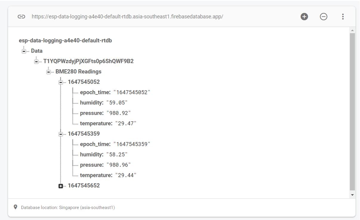
Expanding each individual timestamp, you will be able to view the three sensor readings as follows:
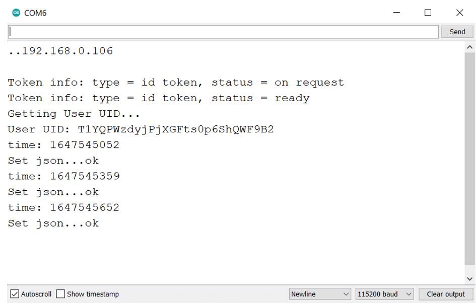
The Arduino serial monitor also shows the relevant messages:
You may also like to read:
- K-Type Thermocouple MAX6675 Amplifier with ESP8266 NodeMCU
- NEO-6M GPS Module with ESP8266 NodeMCU and Track Location on Google Maps
- ESP8266 MPU6050 Web Server Accelerometer and Gyroscope Dashboard with 3-D animation (SSE Events)
- ESP8266 OTA Over The Air Programming using AsyncElegantOTA Library and Arduino IDE
- ESP8266 NodeMCU Web Server Control DC Motor Speed