This MSP430 ADC tutorial teaches you how to use the built-in Analog-to-Digital Converter of the MSP430G2553 microcontroller on the MSP430G2 LaunchPad using the Energia IDE. ADCs are essential for any project that needs to read real-world analog signals — temperature from an LM35, pressure from a strain gauge, light level from an LDR, voltage from a battery, current from an ACS712, or position from a joystick. Because microcontrollers only understand digital signals in binary form, they cannot process analog voltages directly; the on-chip ADC is what bridges the two worlds.
The MSP430G2553 ships with a 10-bit successive-approximation ADC with 8 external channels (A0–A7), so you can read up to eight different analog signals simultaneously from one LaunchPad. In this tutorial we cover ADC fundamentals, the MSP430G2553’s specific capabilities, resolution math with a concrete example, the Energia analogRead() function, and a complete working project: reading a potentiometer and displaying the result on a 16×2 LCD. We finish with a full troubleshooting and FAQ section for common ADC problems.

If you are new to the MSP430G2 LaunchPad or Energia IDE, start with our earlier tutorials in this series before tackling the ADC:
- MSP430G2 LaunchPad Getting Started Tutorial with Energia IDE
- MSP430G2 LaunchPad GPIO Tutorial – Input/Output Pins
- 16×2 LCD Interfacing with MSP430 LaunchPad
- UART Serial Communication with MSP430 Microcontroller
What You Will Learn
- What an Analog-to-Digital Converter (ADC) is and why every microcontroller project eventually needs one
- The difference between ADC channels, resolution (bits), and reference voltage
- The exact ADC specs of the MSP430G2553: 10-bit resolution, 8 channels (A0–A7), 3.3 V reference
- How to calculate the minimum voltage step (LSB) of the MSP430 ADC and convert raw ADC values back to voltage
- Which header pins on the MSP430G2 LaunchPad map to which ADC channels
- The Energia functions that drive the ADC:
analogRead()andanalogReference() - A complete working example: reading a potentiometer and displaying both the raw ADC value and the calculated voltage on a 16×2 LCD
- Common ADC troubleshooting: noisy readings, stuck values, unreliable low voltages, and exceeding the reference
Prerequisites and Required Components
- MSP430G2 LaunchPad (MSP430G2553)
- 10 kΩ potentiometer (for the demo — gives a variable 0–3.3 V input)
- 16×2 character LCD (HD44780) and a 10 kΩ contrast potentiometer
- Breadboard and jumper wires
- USB cable for the LaunchPad
- Energia IDE installed and configured
Introduction to Analog-to-Digital Converters (ADC)
An Analog-to-Digital Converter (ADC) is a circuit that converts a continuous analog signal (typically a voltage) into a discrete digital number that a microcontroller can process. Analog sensors — temperature, hall effect, pressure, PIR motion, light, humidity, current, voltage — produce a continuously varying voltage that represents whatever they are measuring. Because the MSP430 can only store and manipulate binary digital values, the ADC is the gateway between real-world sensors and digital computation.
Three fundamental concepts define any ADC on a microcontroller:
- Channels: how many independent analog inputs the ADC can read. The MSP430G2 LaunchPad has 8 ADC channels (A0–A7), which means up to 8 analog sensors can be connected simultaneously. Only one channel is sampled at a time (a multiplexer switches between them), but the switching is fast enough that you can poll all 8 channels in quick succession.
- Resolution (bits): how many discrete output steps the ADC produces. Common resolutions are 8-bit (256 steps), 10-bit (1024 steps, what the MSP430G2553 uses), 12-bit (4096 steps), and 16-bit (65,536 steps). Higher resolution means finer-grained measurements at the cost of more bits to store.
- Reference voltage (Vref): the known voltage the ADC compares the input against. On the MSP430G2 LaunchPad, Vref defaults to 3.3 V (the VCC rail), but you can switch to the MSP430’s internal 1.5 V or 2.5 V references using
analogReference()for higher accuracy on low-voltage signals.
The input voltage on any ADC channel must stay between 0 V and Vref. Applying a voltage above 3.3 V to an MSP430 ADC pin (or any GPIO, since the MSP430G2553 is not 5 V tolerant) can permanently damage the microcontroller. Use a voltage divider or op-amp buffer to scale down higher voltages first.
For a deeper theoretical background on how SAR (Successive Approximation Register) ADCs work internally, check this video:
MSP430G2 LaunchPad ADC Specifications
The MSP430G2553 integrates a 10-bit ADC10 module. Here are its practical specifications on the MSP430G2 LaunchPad:
- Resolution: 10 bits → output range 0 to 1023
- Channels: 8 external (A0–A7) + internal channels for temperature sensor and Vcc monitoring
- Reference voltage (default): 3.3 V (LaunchPad VCC)
- Internal reference options: 1.5 V or 2.5 V (selectable via
analogReference()) - Sampling rate: up to ~200 ksps at maximum ADC clock
- Architecture: Successive Approximation Register (SAR)
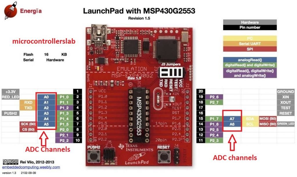
MSP430G2 LaunchPad ADC Pin Mapping
Each ADC channel is tied to a specific MSP430G2553 port pin, which in turn is broken out to a specific LaunchPad header pin. This table shows the complete mapping:
| ADC Channel | MSP430G2553 Pin | LaunchPad Header Pin |
|---|---|---|
| A0 | P1.0 | 2 |
| A1 | P1.1 | 3 |
| A2 | P1.2 | 4 |
| A3 | P1.3 | 5 |
| A4 | P1.4 | 6 |
| A5 | P1.5 | 7 |
| A6 | P1.6 | 14 |
| A7 | P1.7 | 15 |
Note: some of these pins double as the onboard LEDs, push button, and UART pins, so when you use them as analog inputs you lose the onboard functionality. For example, A0 (P1.0, header pin 2) is also the red onboard LED pin — using A0 for analog input means the onboard LED will flicker or stay dim.
MSP430 ADC Resolution — The Math
The resolution of an ADC is the smallest voltage change it can measure — also called the LSB (Least Significant Bit) step. For any ADC:
Resolution = Vref / 2^N
where N is the number of bits. For the MSP430G2553’s 10-bit ADC running at Vref = 3.3 V:
Resolution = 3.3 V / 2^10 = 3.3 V / 1024 ≈ 3.22 mV
That’s your smallest measurable step — 3.22 mV per LSB. An input of 0 V gives an ADC reading of 0; an input of 3.3 V gives an ADC reading of 1023 (the maximum 10-bit value). Every additional millivolt on the input increments the ADC count by about 0.31 counts.
To convert a raw ADC value back to voltage, invert the formula:
Voltage = (ADC_value × Vref) / 1023
        = (ADC_value × 3.3) / 1023
Example: if analogRead() returns 512, the input voltage is (512 × 3.3) / 1023 ≈ 1.65 V. That’s exactly mid-scale — 512 out of 1023 maps to half of 3.3 V, as you would expect.

Higher resolution gives finer measurements. A 12-bit ADC at 3.3 V has a step of 3.3/4096 ≈ 0.81 mV — four times finer than the MSP430G2553’s 10-bit ADC. That’s why higher-end MSP430 parts (and the STM32F4, for example) use 12-bit or 16-bit ADCs: they resolve smaller signal changes at the same reference voltage.
For related ADC tutorials on other microcontrollers:
- ADC with Arduino
- ADC with 8051 Microcontroller
- ADC on STM32F4 Discovery Board
- AC Voltage Measurement with Arduino
How to Read Analog Voltage with the MSP430 in Energia
Just like UART and GPIO, Energia hides the ADC registers behind a simple, Arduino-compatible API. You almost never need to touch ADC10CTL0 or ADC10MEM directly — just call analogRead() and get a number back.
The analogRead() Function
analogRead(channel) samples the analog voltage on the specified channel and returns an integer between 0 and 1023 (for the MSP430G2553’s 10-bit ADC). The argument is the ADC channel name — A0 through A7 — not the header pin number.
int raw = analogRead(A3);    // sample channel A3 (P1.3 / header pin 5)
// raw is now 0 .. 1023
Each call takes tens of microseconds — fast enough to sample a potentiometer, a temperature sensor, or even audio-rate signals (up to a few kHz) in a simple polling loop.
The analogReference() Function
analogReference() lets you switch the ADC’s reference voltage. By default it is VCC (3.3 V on the LaunchPad), but you can change it to an internal 1.5 V or 2.5 V reference for better resolution on low-voltage signals. Valid arguments in Energia: DEFAULT (3.3 V), INTERNAL1V5, INTERNAL2V5, and EXTERNAL (feed a reference voltage into pin P1.4 / VREF+).
analogReference(INTERNAL1V5);   // use internal 1.5 V reference
// Now 0 V = 0 and 1.5 V = 1023. Step = 1.5/1024 ≈ 1.46 mV — much finer
// resolution for sensors that output under 1.5 V (many temperature sensors).
Lowering Vref does not change the ADC’s bit count — it still returns 10-bit numbers — but it spreads those 1024 steps over a smaller voltage range, effectively increasing precision for low-voltage signals.
MSP430 ADC Example: Read a Potentiometer and Display on LCD
Now let’s put it all together in a complete working project. We connect a potentiometer to ADC channel A3 (header pin 5) and display both the raw ADC value and the calculated voltage on a 16×2 LCD. If you haven’t wired up the LCD yet, follow the 16×2 LCD Interfacing with MSP430 LaunchPad tutorial first — the LCD wiring is identical.
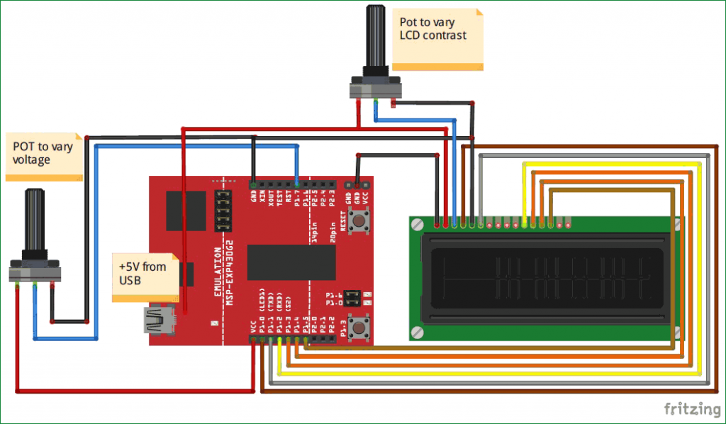
Circuit Connections
- Potentiometer outer pin 1 → 3.3 V
- Potentiometer outer pin 2 → GND
- Potentiometer wiper (center pin) → LaunchPad header pin 5 (A3 / P1.3)
- LCD → wired to the LaunchPad exactly as described in the LCD tutorial (header pins 2, 3, 4, 5, 6, 7 for RS/EN/D4/D5/D6/D7 in 4-bit mode). Note: if you use header pin 5 for both the LCD D5 line and the potentiometer, change one of them — this example uses A4 (header pin 6) instead, and reassigns the LCD D5 line accordingly, to avoid the conflict. The simplest solution is to wire the potentiometer to A7 (header pin 15) which is not used by the LCD in 4-bit mode.
Tip: plan your pin assignments before wiring. The MSP430G2553 only has 16 GPIO pins total, and the LCD alone uses 6 of them in 4-bit mode. Leave header pins 14 and 15 (A6 and A7) free for analog inputs and you avoid conflicts.
Complete Code: ADC + LCD Voltmeter
#include <LiquidCrystal.h>   // built-in LCD library

#define RS 2
#define EN 3
#define D4 4
#define D5 14     // moved from 5 to 14 to free up header pin 5 for ADC
#define D6 6
#define D7 7

LiquidCrystal lcd(RS, EN, D4, D5, D6, D7);

const int potPin = A7;         // wired to header pin 15

void setup() {
  lcd.begin(16, 2);
  lcd.setCursor(0, 0);
  lcd.print("ADC:");
  lcd.setCursor(0, 1);
  lcd.print("Voltage:");
}

void loop() {
  int adcVal = analogRead(potPin);                 // 0..1023
  float voltage = (adcVal * 3.3) / 1023.0;         // convert to volts

  // Update line 1 - raw ADC value
  lcd.setCursor(5, 0);
  lcd.print("     ");            // clear old digits
  lcd.setCursor(5, 0);
  lcd.print(adcVal);

  // Update line 2 - voltage in volts
  lcd.setCursor(9, 1);
  lcd.print("     ");
  lcd.setCursor(9, 1);
  lcd.print(voltage, 2);         // 2 decimal places
  lcd.print(" V");

  delay(200);                    // 5 updates per second
}
Upload the sketch, rotate the potentiometer knob, and watch both the raw ADC value (0–1023) and the corresponding voltage (0.00 V – 3.30 V) update live on the LCD. This is a fully functional digital voltmeter in under 40 lines of code — the same building block you will use for reading temperature sensors, light sensors, current sensors, and any other analog input in your future MSP430 projects.
Troubleshooting MSP430 ADC Issues
- ADC value stuck at 0 or 1023. Either the analog input pin is floating (not connected to any voltage source), or the input exceeds the 3.3 V reference. Verify the wiring with a multimeter — the voltage on the ADC pin should be between 0 V and 3.3 V.
- ADC values jump around randomly. A floating input picks up electrical noise. If the sensor isn’t connected, tie the ADC pin to GND through a 10 kΩ resistor. If a sensor is connected but still noisy, add a 100 nF ceramic capacitor from the ADC pin to GND close to the MSP430 — this filters high-frequency noise.
- Readings are noisy even with a clean input. Take multiple samples and average them:
for (int i = 0; i < 10; i++) total += analogRead(A7); avg = total / 10;. This simple oversampling trick dramatically reduces jitter. - Voltage conversion gives the wrong number. Double-check that Vref in your formula matches the
analogReference()setting. If you switched to INTERNAL1V5, your formula must divide by 1.5, not 3.3. - ADC value does not change when I rotate the potentiometer. Likely a wiring mistake — the center pin of the potentiometer (the wiper) must go to the ADC input, with the outer pins going to 3.3 V and GND. If the outer pins are both connected to the same rail, the wiper produces a constant voltage.
- ADC readings are lower than expected. You may be loading the sensor with a too-low-impedance input. The MSP430G2553’s ADC input impedance is around 2 MΩ but the internal sampling capacitor needs time to charge. For high-impedance sensors (sources above 10 kΩ), allow more settling time or add an op-amp buffer.
- Pin also drives an LED or button. Some of the ADC channels share pins with the onboard LEDs and push button (A0 = red LED pin, A6 = green LED pin, A3 = user button). If you use those channels, remove the corresponding jumper on the J5 block or simply pick a different channel.
Frequently Asked Questions
What is the ADC resolution of the MSP430G2553?
The MSP430G2553 has a 10-bit SAR ADC. That gives 2^10 = 1024 discrete output steps (0 to 1023). With the default 3.3 V reference, the smallest measurable voltage change is 3.3 / 1024 ≈ 3.22 mV per LSB.
How many ADC channels does the MSP430G2 LaunchPad have?
8 external ADC channels (A0 through A7), mapped to Port 1 pins P1.0 through P1.7 respectively. There are also internal channels for the on-chip temperature sensor and VCC monitoring, accessible through Energia’s analogRead(TEMPSENSOR) and similar special-case calls.
How do I convert the MSP430 ADC raw value to voltage?
Use the formula voltage = (adcValue * Vref) / 1023.0. For the default 3.3 V reference: voltage = (adcValue * 3.3) / 1023.0. If you called analogReference(INTERNAL1V5), use 1.5 instead of 3.3.
Can I read negative voltages with the MSP430 ADC?
No. The MSP430G2553’s ADC accepts unipolar inputs only — 0 V to Vref. To measure negative voltages (or any bipolar signal), bias the signal up with an op-amp summer so the entire waveform sits inside 0–3.3 V, then subtract the DC offset in software. Exceeding the 0–3.3 V input range can damage the pin.
What’s the maximum ADC sample rate on the MSP430G2553?
The ADC10 module can sample at up to 200 kilosamples per second with the right clock configuration. In Energia with default settings, a single analogRead() call takes around 125 microseconds (≈8000 sps) which is plenty for most slow-moving sensors like potentiometers, temperature sensors, and light sensors.
How can I read more than 8 analog signals with one MSP430?
Two options: (1) use an external analog multiplexer like the CD74HC4067 (16-channel) or CD74HC4051 (8-channel), which lets you switch many analog inputs into a single ADC channel under digital control; or (2) use an external ADC chip with I2C or SPI interface, such as the ADS1115 (16-bit, 4-channel) — at that point the MSP430’s built-in ADC is bypassed entirely.
Conclusion
You now know how to use the ADC of the MSP430 microcontroller on the MSP430G2 LaunchPad with the Energia IDE. You learned the three key concepts (channels, resolution, reference voltage), the specifications of the MSP430G2553’s 10-bit ADC, how to calculate LSB voltage and convert raw ADC readings back to volts, and how to read a real potentiometer in a complete working ADC-plus-LCD project. Every analog sensor you ever connect to an MSP430 — temperature, light, current, pressure, humidity — follows the same pattern: read with analogRead(), scale with the reference voltage, display or transmit the result. Next in this series we explore PWM, the output equivalent of the ADC.
Related MSP430G2 LaunchPad Tutorials
- MSP430G2 LaunchPad Getting Started Tutorial with Energia IDE
- MSP430G2 LaunchPad GPIO Tutorial – Input/Output Pins
- RGB LED Interfacing with MSP430G2 LaunchPad
- PIR Motion Sensor Interfacing with MSP430G2 LaunchPad
- 16×2 LCD Interfacing with MSP430 LaunchPad
- UART Serial Communication with MSP430 Microcontroller
- Pulse Width Modulation using MSP430 LaunchPad
My name is Hariz Azmi and a student. Currently do this project. Can you help me do this project? Really need your help. I try do my best to learn. Hope can contact you.
Thank you.