In this Arduino based tutorial, we will learn how to build an obstacle avoidance robot using Arduino Uno R3 and HC-SR04 ultrasonic sensor. Obstacle avoidance robot works with self-intelligence. If there is any hurdle or obstacle in its way, it turns its direction automatically. The ultrasonic sensor is the main component of our project that is used to detect obstacles. The basic purpose of the ultrasonic sensor is to measure the distance from any obstacle in front of it. This distance measurement concept is used to change the direction of the robot when the robot is at some distance close to handling or obstacle. HC-SR04 Ultrasonic sensor is used in this project.
Obstacle Avoidance Robot Overview
We will require the following hardware components to build our obstacle avoidance robot.
Required Components:
- Arduino Uno R3
- 4 DC motors and wheels
- HC-RS04 ultrasonic sensor
- L298 DC motor driver
- 4 wheel car chassis
- Servo Motor
- 12V external power supply
- Resistors (optional)
Our obstacle avoidance robot will be built using an HC-RS04 ultrasonic sensor that will be mounted on a servo motor. The servo motor will move the sensor to look for a path. The ultrasonic sensor will determine the distance of a nearby object. If there is an object less than 15 centimeters away, the robot will stop. Then it looks around, turns toward a direction in which it doesn’t sense anything, and move in that direction.
We will require four dc motors to control the speed and direction of rotation of the robot as we will be using a 4 wheel car chassis. It is very easy to interface DC motors with Arduino using L293D dc motor driver. L298 is a dc motor driver which is used to rotate motors in a clock wise or anti clock wise direction. It is used to turn robot right, left, reverse and straight. It is a great option to drive several motors using Arduino and used in projects such as four-wheeled robots. This driver shield is able to drive 4 dc motors, 2 unipolar/bipolar stepper motors, or 2 servo motors simultaneously.
Recommended Reading: Arduino L293D Motor Driver Shield Control DC, Servo, and Stepper Motors
Let us first learn about the HC-SR04 sensor.
HC-SR04 Ultrasonic Sensor for Obstacle Avoiding Robot
The ultrasonic sensor is a distance measurement sensor which uses ultrasonic waves to measure distance. HC-SR04 ultrasonic sensor has ultrasonic waves transmitter and receiver which is used to measure distance with the help of reflection time of ultrasonic waves from a transmitter to back into the receiver.
Recommended Reading: Ultrasonic sensor interfacing with Arduino and distance measurement
To interface the HC-SR04 ultrasonic sensor with Arduino, we should know the functionality of each pin of the ultrasonic sensor. By knowing the functionality of input and output pins, we will be able to identify which pins of Arduino should be used to interface with HC-SR04.
HC-SR04 Pinout
The figure given below shows the pin configuration of an ultrasonic sensor. It consists of four pins namely; Vcc, Ground, Trigger, and Echo pin.
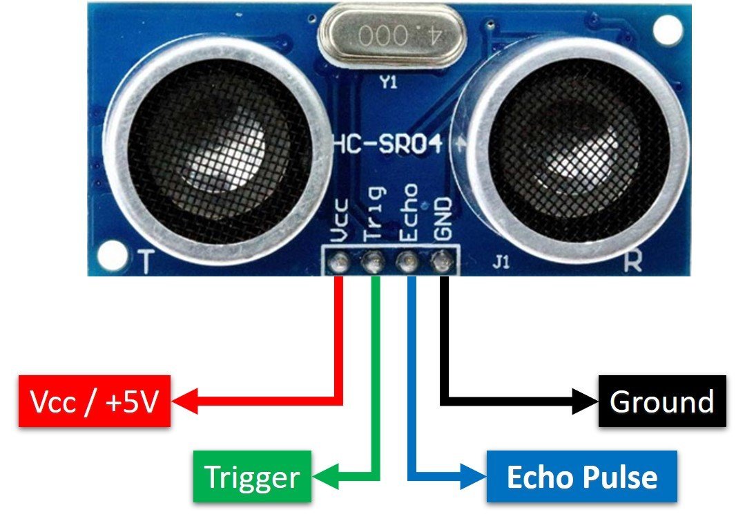
Vcc and Ground are used to power sensor. We should supply 5 volts to the Vcc pin and connect the GND pin with the ground terminal of the power supply.
Trigger: It is an input pin. A trigger pin is used to initiate the ultrasonic sensor to start distance measurement or distance ranging. When users want to get distance measurements from the sensor, we apply a 10µs pulse to this pin.
Echo: This is a pulse output pin. The echo pin produces a pulse as an output. The width of pulse or on-time of the pulse depends on the distance between the ultrasonic sensor and the obstacle which is placed in front of the HC-SR04 sensor. In idle conditions, this pin remains at an active low level.
Further details on ultrasonic sensor working are provided in the next section.
How HC-SR04 Sensor Works?
HC-SR04 ultrasonic sensor measures distance by using inaudible ultrasonic sound waves of 40KHz frequency. Like sound waves, ultrasonic waves travel through the air and if there is any obstacle in front of them, they reflect according to their angle of incidence. Moreover, if an object is placed parallel to an ultrasonic transmitter, ultrasonic waves reflect exactly at an angle of 180 degrees. Therefore, for distance measurement with HC-SR05 sensor, we place the object under test exactly in a parallel position with an ultrasonic sensor as shown in the figure below.
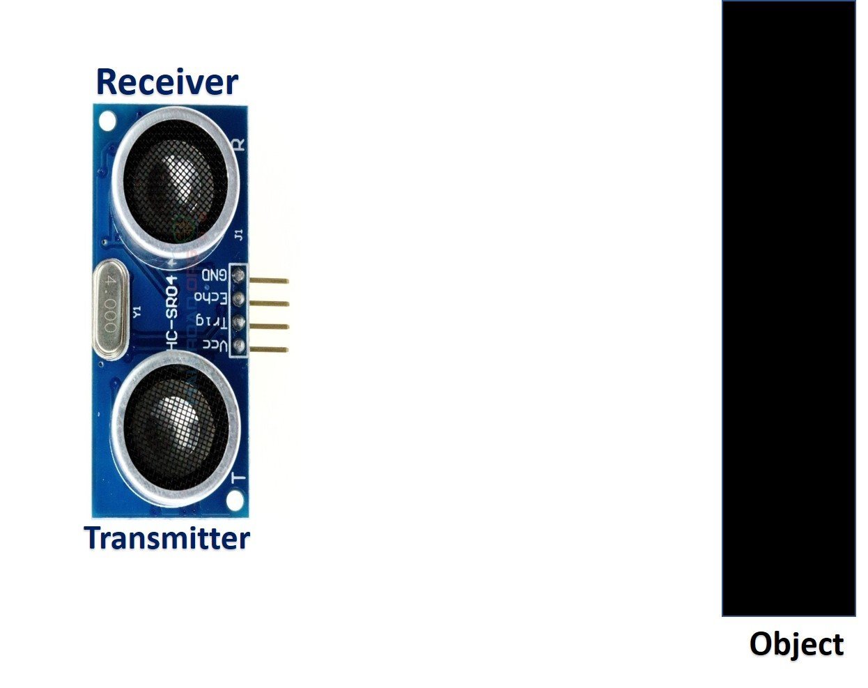
HC-SR04 ultrasonic sensor consists of two basic modules such as an ultrasonic transmitter and an ultrasonic receiver module. The transmitter circuit converts an electrical signal into a 40KHz burst of 8 sonar wave pulses. The input electrical signal to the transmitter circuit is 10µs pulse input to the trigger pin of the HC-SR04 sensor. As we mentioned earlier, we apply this trigger input signal through Arduino UNO R3. On the other hand, the ultrasonic receiver circuit listens to these ultrasonic waves which are produced by the transmitter circuit.
Measure HC-SR04 Echo Pulse Time with Arduino
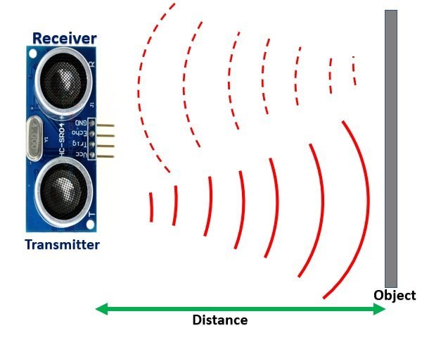
- To start ranging with HC-SR04, first, we apply 10µs pulse to the trigger pin of the HC-SR04 sensor from the Arduino digital output pin.
- As soon as 10µs input trigger signal becomes active low, the transmitter circuit produces a burst of 8 ultrasonic sonar pulses. At the same time, the Echo pin also makes a transition from a logic low level to a logic high level.
- When the Echo pin goes high, We start to measure time with the Arduino duration measurement function.
- These waves travel through the air and if there is any object placed in parallel to the sensor, these waves reflect back after a collision with the object.
- As soon as the ultrasonic waves received by the receiver circuit after striking with an object, the echo pin goes low. Arduino detects this transition of echo output signal from active high to an active low level and stops the measurement.
In short, by measuring the on-time of the Echo output pulse signal, we can measure the distance. The following figure illustrates the echo output signal with respect input trigger signal and 8 sonar pulses.
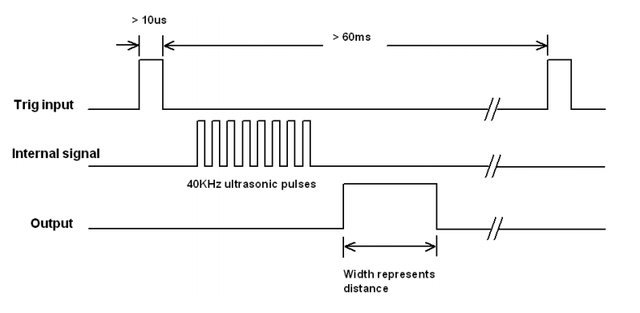
The duration for which the echo output signal remains high depends on the distance between the ultrasonic sensor and the object which we place in front of the sensor. Higher is the distance, the higher the time sonar waves will take to reach back to the ultrasonic receiver circuit. Because ultrasonic waves travel through the air with the speed of sound and speed remains constant.
How to Convert Time Duration into Distance
In the next section, we will see how to measure pulse duration using Arduino. Let’s assume that we have measured the output pulse on time (t) with Arduino. Now the question is how to convert this measured time into distance.
Well, this is the most obvious part of this tutorial. In high school, we all studied a well-known distance-time equation that is S = vt. We can convert the pulse duration (t) into the distance (S) using this equation.
Distance (S) = Speed (v) * t //distance in metersHere v is the speed of ultrasonic waves in air. The speed of ultrasonic waves in air is equal to the speed of sound which is 340 m/s (meter per second).
The above equation will give distance output in units of meter. But, if you want the distance in centimeter units, multiply 340 with 100. Hence, the above equation becomes:
S = 34000 * t // distance in cmThe time given in the above formula should also be divided by two. Because ultrasonic waves travel from the transmitter to the obstacle and then reflect back to the receiver circuit by traveling the same distance. We want to find the distance between HC-SR04 and the object only. Therefore, the formula to calculate distance becomes :
S = 17000 * t // distance in cmNote: You don’t need to worry about these calculations as we will be using the NewPing library for the HC-SR04 ultrasonic sensor to take distance measurements.
Circuit diagram of Obstacle Avoiding Robot using L293D Motor Driver Shield
Let us learn how to interface all the components together to build the obstacle avoidance robot.
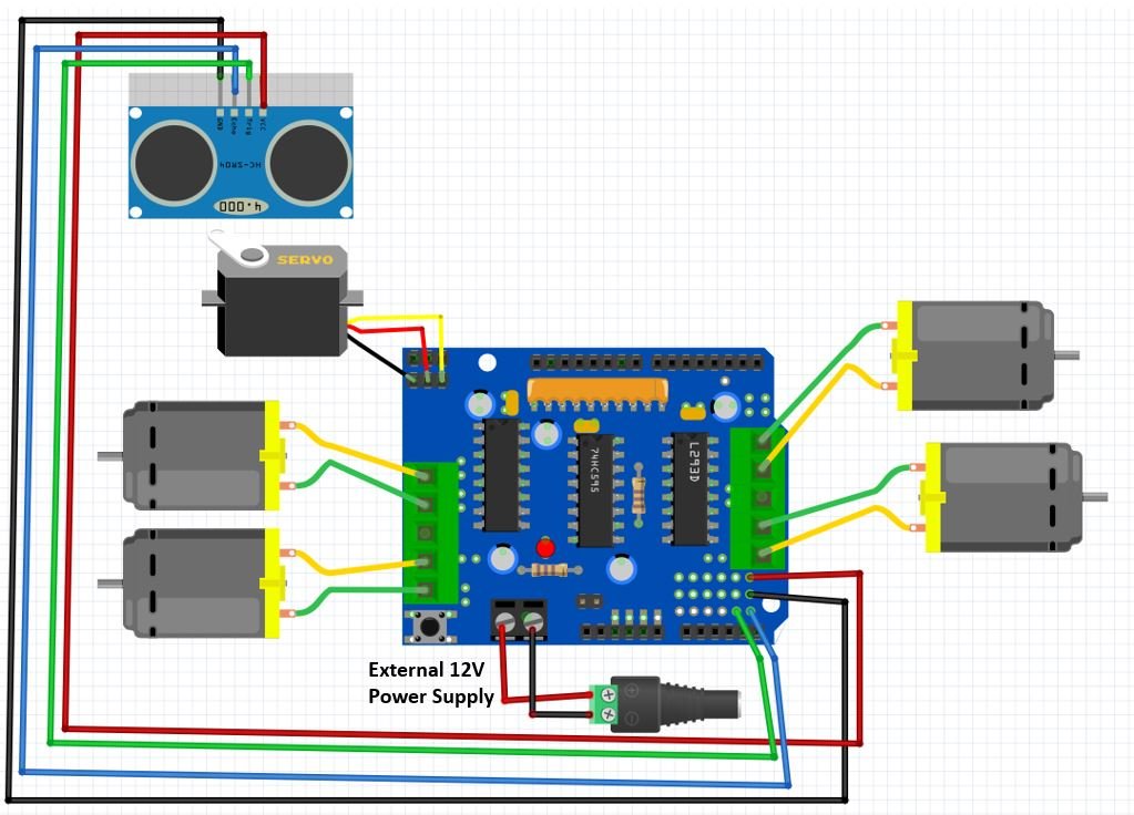
DC Motors with L293D Motor Driver Shield
The first step is to mount the L293D motor driver shield on the Arduino board. Then we will connect 4 DC motors with M1 (port 1), M2 (port 2), M3 (port 3), and M4 (port 4) terminals respectively.
We are using TT DC gear motors for this project. They require an operating voltage of 3-12V DC where the recommended operating voltage is 3-6V DC. Connect the positive terminal of power supply with +M terminal and negative terminal with GND terminal found at the EXT_PWR terminal block on the shield. Also, the power jumper is removed from the shield.
Ultrasonic Sensor with L293D Motor Driver Shield
To interface an HC-SR04 sensor with Arduino, we need four pins out of which two are power supply pins and two are analog pins. One analog pin of the Arduino will be connected with the trigger pin and one analog pin will be connected with echo pin to capture echo output signal of sensor.
| HC-SR04 | Arduino |
|---|---|
| VCC | 5V |
| GND | GND |
| Trigger | A4 |
| Echo | A5 |
You can solder 4 jumper wires in order to connect the ultrasonic sensor to Arduino via the motor driver shield.
Additionally, attach the ultrasonic sensor on top of the servo motor’s arms so that the robot can detect obstacles in its path and change direction. This should be placed at the front of the robot, with the ultrasonic sensor facing forwards.
Servo Motor with L293D Motor Driver Shield
Then we will connect a servo motor with one of the three pin headers found at the top left of the shield.
We will use SG90 servo motor for this project. SG90 is a low cost and high output power servo motor. It can rotate up to 180 degrees and each step can be of maximum 90 degrees.
It consists of three pins only: PWM, ground and VCC pin. If connecting the servo motor with the first header pins, the PWM pin of the servo motor will get connected with PWM pin10 of Arduino board. Likewise if connecting the motor with the second header pins, the PWM pin of the servo motor will get connected with the PWM pin9 of the Arduino board.
Additionally, we will not require an external power source to power the motor as the 5V from Arduino will be adequate to power the motor.
Obstacle Avoidance Robot using Arduino L293D Motor Driver Shield and HC-SR04
For this project, we will require two libraries that we will install from the Arduino IDE Library Manager.
Firstly, we will require the Motor Shield Library by Adafruit present in Arduino Library Manager to control the motors with our Arduino L293D motor shield. This library will provide us with useful functions to set the speed and change the direction of rotation.
To install the library, we will use the Arduino Library Manager. Open your Arduino IDE and go to Sketch > Include Libraries > Manage Libraries. Type ‘adafruit motor shield’ in the search bar and install the latest version.
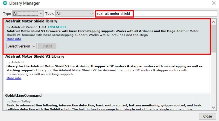
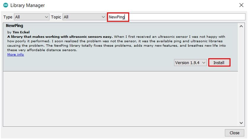
Secondly, we will require the NewPing present in Arduino Library Manager to easily work with the ultrasonic sensors.
To install the library, we will use the Arduino Library Manager. Open your Arduino IDE and go to Sketch > Include Libraries > Manage Libraries. Type ‘NewPing’ in the search bar and install the latest version.
Obstacle Avoiding Robot Arduino Code
Open your Arduino IDE and go to File > New. A new file will open. Copy the code given below in that file and save it.
#include <AFMotor.h>
#include <NewPing.h>
#include <Servo.h>

#define TRIG_PIN A4
#define ECHO_PIN A5
#define MAX_DISTANCE 100
#define MAX_SPEED 80 // sets speed of DC motors
#define MAX_SPEED_OFFSET 20

NewPing sonar(TRIG_PIN, ECHO_PIN, MAX_DISTANCE);

AF_DCMotor motor1(1, MOTOR12_1KHZ);
AF_DCMotor motor2(2, MOTOR12_1KHZ);
AF_DCMotor motor3(3, MOTOR12_1KHZ);
AF_DCMotor motor4(4, MOTOR12_1KHZ);

Servo myservo;

boolean goesForward=false;
int distance = 100;
int speedSet = 0;

void setup() {

myservo.attach(9);
 myservo.write(115);
 delay(2000);
 distance = readPing();
 delay(100);
 distance = readPing();
 delay(100);
 distance = readPing();
 delay(100);
 distance = readPing();
 delay(100);
}

void loop() {
 int distanceR = 0;
 int distanceL = 0;
 delay(40);

 if(distance<=30)
 {
 moveStop();
 delay(100);
 moveBackward();
 delay(300);
 moveStop();
 delay(200);
 distanceR = lookRight();
 delay(200);
 distanceL = lookLeft();
 delay(200);

if(distanceR>=distanceL)
 {
 turnRight();
 moveStop();
 }else
 {
 turnLeft();
 moveStop();
 }
 }else
 {
 moveForward();
 }
 distance = readPing();
}

int lookRight()
{
 myservo.write(50);
 delay(500);
 int distance = readPing();
 delay(100);
 myservo.write(115);
 return distance;
}

int lookLeft()
{
 myservo.write(170);
 delay(500);
 int distance = readPing();
 delay(100);
 myservo.write(115);
 return distance;
 delay(100);
}

int readPing() {
 delay(70);
 int cm = sonar.ping_cm();
 if(cm==0)
 {
 cm = 250;
 }
 return cm;
}

void moveStop() {
 motor1.run(RELEASE);
 motor2.run(RELEASE);
 motor3.run(RELEASE);
 motor4.run(RELEASE);
 }

void moveForward() {

if(!goesForward)
 {
 goesForward=true;
 motor1.run(FORWARD);
 motor2.run(FORWARD);
 motor3.run(FORWARD);
 motor4.run(FORWARD);
 for (speedSet = 0; speedSet < MAX_SPEED; speedSet +=2) // slowly bring the speed up to avoid loading down the batteries too quickly
 {
 motor1.setSpeed(speedSet);
 motor2.setSpeed(speedSet+MAX_SPEED_OFFSET);
 motor3.setSpeed(speedSet);
 motor4.setSpeed(speedSet+MAX_SPEED_OFFSET);
 delay(5);
 }
 }
}

void moveBackward() {
 goesForward=false;
 motor1.run(BACKWARD);
 motor2.run(BACKWARD);
 motor3.run(BACKWARD);
 motor4.run(BACKWARD);
 for (speedSet = 0; speedSet < MAX_SPEED; speedSet +=2) // slowly bring the speed up to avoid loading down the batteries too quickly
 {
 motor1.setSpeed(speedSet);
 motor2.setSpeed(speedSet+MAX_SPEED_OFFSET);
 motor3.setSpeed(speedSet);
 motor4.setSpeed(speedSet+MAX_SPEED_OFFSET);
 delay(5);
 }
}

void turnRight() {
 motor1.run(BACKWARD);
 motor2.run(BACKWARD);
 motor3.run(FORWARD);
 motor4.run(FORWARD);
 delay(300);
 motor1.run(BACKWARD);
 motor2.run(BACKWARD);
 motor3.run(FORWARD);
 motor4.run(FORWARD);
 delay(300);
 motor1.run(BACKWARD);
 motor2.run(BACKWARD);
 motor3.run(FORWARD);
 motor4.run(FORWARD);
 delay(300);
 motor1.run(FORWARD);
 motor2.run(FORWARD);
 motor3.run(FORWARD);
 motor4.run(FORWARD);
}

void turnLeft() {
 motor1.run(FORWARD);
 motor2.run(FORWARD);
 motor3.run(BACKWARD);
 motor4.run(BACKWARD);
 delay(300);
 motor1.run(FORWARD);
 motor2.run(FORWARD);
 motor3.run(BACKWARD);
 motor4.run(BACKWARD);
 delay(300);
 motor1.run(FORWARD);
 motor2.run(FORWARD);
 motor3.run(BACKWARD);
 motor4.run(BACKWARD);
 delay(300);
 motor1.run(FORWARD);
 motor2.run(FORWARD);
 motor3.run(FORWARD);
 motor4.run(FORWARD);
}
How does the Code Works?
Firstly, we will include the AFMotor.h library. This library provides useful functions that make it easy to control the motors using Arduino. Also, we will include the built-in Servo.h library for the servo motor and the NewPing library to work with the ultrasonic sensor.
#include <AFMotor.h>
#include <NewPing.h>
#include <Servo.h>
Next, define the names of Arduino pins using #define preprocessor directives. This defines that A4 and A5 pins of Arduino are used to control trigger and echo pins of the HC-SR04 sensor.
#define TRIG_PIN A4
#define ECHO_PIN A5
Next set the maximum distance, maximum speed and its offset values.
#define MAX_DISTANCE 100
#define MAX_SPEED 80 // sets speed of DC motors
#define MAX_SPEED_OFFSET 20
Then we will initialize the ultrasonic sensor by providing the trigger pin, echo pin and the maximum distance as parameters inside the NewPing object.
NewPing sonar(TRIG_PIN, ECHO_PIN, MAX_DISTANCE);
Next we will create four instances of AF_DCMotor called motor1, motor2, motor3. We will specify the motor port we are connecting our motor with as the first parameter and the PWM frequency as the second parameter.
AF_DCMotor motor1(1, MOTOR12_1KHZ);
AF_DCMotor motor2(2, MOTOR12_1KHZ);
AF_DCMotor motor3(3, MOTOR12_1KHZ);
AF_DCMotor motor4(4, MOTOR12_1KHZ);
Then we will create an object of this library called ‘servo.’
Servo myservo;
We will create few other variables to control the robot as you will see later on in the code.
boolean goesForward=false;
int distance = 100;
int speedSet = 0;
Servo Motion Movement
The lookRight() and lookLeft() functions will position the servo motor’s arm at appropriate positions. Then we will call the readPing() function and save its value in the variable distance. This value will be returned.
int lookRight()
{
 myservo.write(50);
 delay(500);
 int distance = readPing();
 delay(100);
 myservo.write(115);
 return distance;
}

int lookLeft()
{
 myservo.write(170);
 delay(500);
 int distance = readPing();
 delay(100);
 myservo.write(115);
 return distance;
 delay(100);
}
The readPing() function will send a ping and get the distance in centimeters. This will be saved in the variable ‘cm’.
int readPing() {
 delay(70);
 int cm = sonar.ping_cm();
 if(cm==0)
 {
 cm = 250;
 }
 return cm;
}
DC Motors Movement
The moveStop() function will be used to stop the robot. We will use the run() method on the motor instances with ‘RELEASE’ as an argument inside it to stop all the motors.
void moveStop() {
 motor1.run(RELEASE);
 motor2.run(RELEASE);
 motor3.run(RELEASE);
 motor4.run(RELEASE);
 }
The moveForward() function will be responsible for moving the robot in forward direction. It will also manage the speed of all the motors to keep them within the maximum speed already set before.
void moveForward() {

if(!goesForward)
 {
 goesForward=true;
 motor1.run(FORWARD);
 motor2.run(FORWARD);
 motor3.run(FORWARD);
 motor4.run(FORWARD);
 for (speedSet = 0; speedSet < MAX_SPEED; speedSet +=2) // slowly bring the speed up to avoid loading down the batteries too quickly
 {
 motor1.setSpeed(speedSet);
 motor2.setSpeed(speedSet+MAX_SPEED_OFFSET);
 motor3.setSpeed(speedSet);
 motor4.setSpeed(speedSet+MAX_SPEED_OFFSET);
 delay(5);
 }
 }
}
Likewise, the moveBackward() function will be responsible for moving the robot in backward direction. It will also manage the speed of all the motors to keep them within the maximum speed already set before.
void moveBackward() {
 goesForward=false;
 motor1.run(BACKWARD);
 motor2.run(BACKWARD);
 motor3.run(BACKWARD);
 motor4.run(BACKWARD);
 for (speedSet = 0; speedSet < MAX_SPEED; speedSet +=2) // slowly bring the speed up to avoid loading down the batteries too quickly
 {
 motor1.setSpeed(speedSet);
 motor2.setSpeed(speedSet+MAX_SPEED_OFFSET);
 motor3.setSpeed(speedSet);
 motor4.setSpeed(speedSet+MAX_SPEED_OFFSET);
 delay(5);
 }
}
The turnRight() function will move the robot to the right direction whereas the turnLeft() function will move the robot to the left direction. This is done by moving the four motors in specific directions with a slight delay in between them.
void turnRight() {
 motor1.run(BACKWARD);
 motor2.run(BACKWARD);
 motor3.run(FORWARD);
 motor4.run(FORWARD);
 delay(300);
 motor1.run(BACKWARD);
 motor2.run(BACKWARD);
 motor3.run(FORWARD);
 motor4.run(FORWARD);
 delay(300);
 motor1.run(BACKWARD);
 motor2.run(BACKWARD);
 motor3.run(FORWARD);
 motor4.run(FORWARD);
 delay(300);
 motor1.run(FORWARD);
 motor2.run(FORWARD);
 motor3.run(FORWARD);
 motor4.run(FORWARD);
}

void turnLeft() {
 motor1.run(FORWARD);
 motor2.run(FORWARD);
 motor3.run(BACKWARD);
 motor4.run(BACKWARD);
 delay(300);
 motor1.run(FORWARD);
 motor2.run(FORWARD);
 motor3.run(BACKWARD);
 motor4.run(BACKWARD);
 delay(300);
 motor1.run(FORWARD);
 motor2.run(FORWARD);
 motor3.run(BACKWARD);
 motor4.run(BACKWARD);
 delay(300);
 motor1.run(FORWARD);
 motor2.run(FORWARD);
 motor3.run(FORWARD);
 motor4.run(FORWARD);
}
setup()
Inside the setup() function, we will first attach digital pin9 with the servo object. Notice this is the GPIO pin that is connected with the PWM pin of the servo motor. Then we will position the servo motor’s arm at 115 degrees using the write() method on the servo object. After every few seconds we will call the readPing() function and save its value in the variable distance.
void setup() {

 myservo.attach(9);
 myservo.write(115);
 delay(2000);
 distance = readPing();
 delay(100);
 distance = readPing();
 delay(100);
 distance = readPing();
 delay(100);
 distance = readPing();
 delay(100);
}
loop()
Inside the infinite loop(), we compare the reading of the distance that we get from the ultrasonic sensor. If the robot finds an object less than 30 centimeters away, then first all the motors will stop. Then the robot will move backward and then stop again. At this point the servo motor moves left and right and saves the distances in their respective variables (distanceR and distanceL). If distanceR is greater than distanceL then the motors move towards the right direction and then stop otherwise they move in the left direction and then stop momentarily. The robot moves in the forward direction and continuously takes distance readings to monitor obstacles.
void loop() {
 int distanceR = 0;
 int distanceL = 0;
 delay(40);

 if(distance<=30)
 {
 moveStop();
 delay(100);
 moveBackward();
 delay(300);
 moveStop();
 delay(200);
 distanceR = lookRight();
 delay(200);
 distanceL = lookLeft();
 delay(200);

if(distanceR>=distanceL)
 {
 turnRight();
 moveStop();
 }else
 {
 turnLeft();
 moveStop();
 }
 }else
 {
 moveForward();
 }
 distance = readPing();
}
Obstacle Avoiding Robot Demonstration
To see the demonstration of the above code, upload the code to Arduino. Before uploading the code, make sure to select Arduino UNO from Tools > Board.
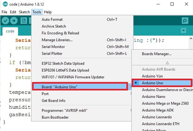
Also, select the correct COM port to which the Arduino board is connected from Tools > Port.
Once the code is uploaded to your board, the robot will start moving and avoiding obstacles in its path.
Watch the video demonstration below:
You may also like to read:
How it can be so Simple? And you mentioned resistors in hardware components but not in Circuit Diagram ?
you can use resistors as current limitor but there is need in this circuit diagram
Can u please upload the code on this instructable. I am getting problem opening the code.
Can u please upload the code
I shared a link for the code of obstacle avoidance robot
HEY BILAL .. DO WE NEED RESISTORS? IF YES WHERE DO I CONNECT THEM?
HOW MANY OHMS? HOW MANY?
Why is the frequency different for the two motors ?
indeed why is it so
This code is no longer available. Any chance you could email it to me?
The code isn’t at http://www.4shared.com/file/raRMX53lce/Obstacle_Avoiding_Robot_Code.html
Anywhere else?
the code is nolonger available, do you emailing it to me?
Can someone give me the code for my arduino robot ..it has arduino uno R3 , L293D motor driver , HC-SR04 ultrasonic , 2 dc motors , and IR remote with receiver module ?
How can i connect a L293d Motor driver instead of motor driver shield. Where i need to connect the Control signal pins od l293d ic?. Is there any change in the coding.?
What is the rating of dc motors used here? What is the rpm?
Can u please provide the DC motor library file. That you mentioned above.
Please where can I buy the components. I want to make one as a project
Can someone give me the code for my
arduino robot ..it has arduino uno R3 ,
L293D motor driver , HC-SR04 ultrasonic ,
2 dc motors ?
MY E-MAIL ADDRESS: delhijewellers@hotmail.com