Design of multiple input charge controller is an efficient voltage conversion system for multiple inputs and combine output. Objective is designing of a system to extract multiple resources without mixing them with each other. Firstly it is Designed and Simulated in software like Proteus, MATLAB, code-Vision, Micro-C and then finally demonstrated in hardware form. This will include the design of a charge controller with variable frequency and variable duty cycle. Potential customers of this project could be individuals and organizations opting to implement hybrid renewable energy sources to feed a single load. This hardware is quite useful to operate household and industrial electronic devices directly from renewable energy sources eliminating converter losses of household and industrial electronic devices.
MULTIPLE INPUT CHARGE CONTROLLER
Our project is related with the design and fabrication of multiple input voltage controllers for renewable energy resources. The demand of renewable energy sources is increasing day by day because of the shortage of conventional energy resources and due to its several benefits and applications also renewable energy sources are clean and they are not harmful for our environment. Most of the electrical systems are supplied with one kind of energy source; we will design multiple input voltage controllers which take input from different renewable energy resources at same time and regulate the input voltage. The MULTIPLE INPUT VOLTAGE CONTROLLER is like a DC-DC converter which actually works as the step up or boost converter. First we will design DC-AC converter which takes DC input from the renewable energy resources, then we will convert this DC input into AC through H-BRIDGE and use a transformer to provide isolation between input and output circuits and to step up the voltage level according to our demand, and we will be changing the duty cycle as well as frequency, the frequency should be in the range of 20KHZ to 50KHZ, then we will design AC-DC converter which finally rectified that AC voltage level into DC voltage which should not be increased then 15 volts. This output voltage is useful for fuel cells, for battery applications and for automobiles applications and other uses.
Applications of MULTIPLE INPUT CHARGE CONTROLLER
Consumption of global energy is continuously growing. To satisfy the demand for electric power against a background of the depletion of conventional fossil resources the renewable energy sources are becoming more popular. According to researches despite its weather dependency and fluctuating nature the renewable resources capacity can satisfy overall demand for energy. Recently, DC based power systems locally distributed have become attractive due to the increase in the use of renewable energy resources. DC has many advantages over AC Counterparts.The R and D efforts and international investments are focused on reduction in renewable energy production cost. High gain of DC to DC converters is a key part of system of renewable energy. The designing of high gain DC to DC converters is done through severe demands. Designers face contradictory constraints like high reliability and low cost.
Since the renewable sources could be utilized for many years the converter designers can cope with long time issues of reliability. The main problem for the operator was minimize the maintenance and to maximize the energy yield. For these reasons the converters must be made by high efficiency over wide voltage range and input power. Additionally they should be operated at wide temperature ranges by expressing low EMC emission and also be immune to different environmental conditions. Such demands create severe constraint for DC to DC boost converter designing that are key parts in terms of efficiency for overall renewable energy system. High step-up dc/dc converters are widely used in many applications. Thus, the high step-up dc to dc converter needs very high voltage gain, small volume and high efficiency.
Theoretically, a conventional boost converter could be adopted to provide a high step-up voltage gain with extremely high duty ratio. In practice, the step-up voltage gain was limited by the effects of rectifier diode power switch, and equivalent series resistance (ESR) of capacitor and inductor. Also, the extremely high duty-ratio operation might result in serious reverse recovery problem, low efficiency, and the electromagnetic interference (EMI) problem.
According to the cost of setup a DC power system was cheaper when overhead line distance was less than 500 miles. Also, the DC line requires smaller towers so that less space was needed to setup. The simplicity of connection also simplifies the architecture of power system in local area. Moreover, there was no alternating magnetic field around the conductor, so inductive and capacitive effects does not exist. Inductance of transmission line was zero and capacitance exists between conductors was open circuit for DC, so only real power was transmitted.
Since power factor was always unity, reactance compensation was no longer necessary. Therefore, both the power transfer capacity of the line and also the efficiency of system were higher. The frequency was always zero in the DC supply; thus, no synchronous procedure was required to connect the two DC power systems. This provides the ease to increase system’s power when the demand was large. In addition, DC power flow was independent from the load and was controllable by adjusting delay angles at terminals.Advantages of using DC power system, especially for a local distribution has brought us to the idea of establishing a DC house for areas that are unreachable by the power grid.
SCOPE OF MULTIPLE INPUT CHARGE CONTROLLER
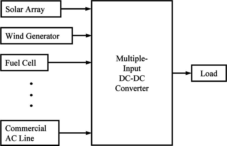
RECENTLY, the zero-emission electrical power generation systems had been developed aggressively to exploit the clean energy resources such as wind generator, the solar array, fuel cell, and so forth. In this case, the multiple input dc/dc converter was useful to combine several inputs power sources whose voltage level or power capacity were different and to get regulated output voltage for load from them.In solar array power supply systems with commercial ac line, the maximum power point of the solar array could easily be tracked while simultaneously the output voltages could be easily regulated by receiving an adequate power from the commercial ac line, even if the load was changed.
SELECTION MULTIPLE INPUT CHARGE CONTROLLER
The motivation behind choosing this project was to develop a converter by using renewable sources that was capable of interfacing different current-voltage characteristics sources to a common load, while achieving low part count. A fixed frequency switching strategy was investigated and resulting operating modes were analyzed. The analysis was verified by experimentation.Most of the electrical systems were supplied by one kind of energy sources, whether it is wind, batteries, solar, utility etc. Certain special cases were powered by two sources i.e. Uninterruptible power supplies. Future power systems would also require interfacing of energy sources of almost all kinds. Renewable energy sources would be of particular interest, especially as resources will further distributed about terrestrial power grid. In is landed power systems,
interfacing of different multiple sources allows for the improved reliability, flexibility, and also utilization of the preferred energy sources.Different sources such as photovoltaic and fuel cells, and batteries will have different voltage and voltage characteristics. In most cases, one source might be preferential to others, or perhaps, the simultaneous combination of sources was appropriate for the optimal energy and economic use. Therefore, multiple input power converters are required so as to enable multiple-source technology. Such converters had received limited attention, so far. A topology for achieving combinations of these multiple dc sources is presented in this project. The different operating modes were investigated and also verified by experimentation.
With multiple inputs, the energy source was diversified so as to increase reliability and also the utilization of renewable sources. An ideal multiple-input power supply can accommodate a variety of sources and then combine their advantages automatically, such that inputs are interchangeable. Such converter can be relocated and can still take advantage of various local environments, e.g. in some areas solar power will be readily accommodated while in others, utility power might be especially reliable or may be inexpensive. Most of the renewable sources have dc current and voltage characteristics. Therefore, a multiple input dc/dc converter is of very practical use.
Working of MULTIPLE INPUT CHARGE CONTROLLER
The project deals with the designing of a high frequency DC to DC boost converter by using commercially available parts. The first step in that process was the creation of very high frequency DC-DC boost converter. A DC-DC boost converter deals with the taking of an input voltage and therefore producing a higher voltage. Most commercially available boost converters cannot exceed the frequency of almost 5MHz. But the boost converter required for our project is needed to be capable of operating at a very high frequency i.e. 20MHz, four times larger than commercially available.
The final outcome was a fully functional and continuous conduction mode’ boost converter that was soldered to printed circuit board. It was capable of achieving constant 12-14 V output from a 6-10V input. Increasing the switching frequency of the boost converter will allow for smaller passive component values and will allow the whole device to be militarized with minimal additional effort. Hence finally, the efficiency is calculated to be more than 85%.
Block diagram of MULTIPLE INPUT CHARGE CONTROLLER
This block diagram represents that the multiple inputs can be formed from renewable sources like batteries, wind mills and solar array etc. Furthermore their outputs are combined through a DC-DC converter and then this output is fed to load.
Components of multiple input charge controller
- Inverter circuit (H-bridge)
- Micro-controller (Triggering unit)
- Driver unit (Control circuit)
- Output rectifier circuit
- DC-load
INVERTER CIRCUIT of multiple input charge controller
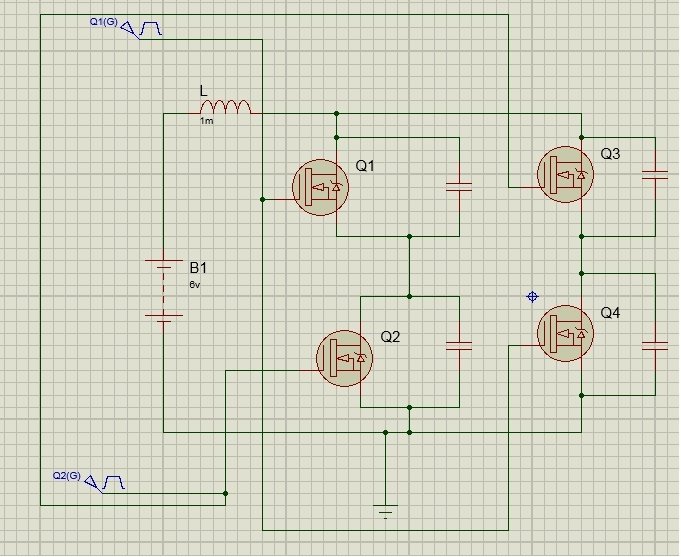
A DC supply is given to the inverter circuit. The inverter converts DC input power into AC power. In order to increase the efficiency of converter DC input voltage is converted into AC voltage. In our design inverter is made up of power MOSFET’S. 4 powers MOSFET’S are required in one module to make H-BRIDGE.The MOSFET which we used in our software designing is IRF3704. These are high frequency power MOSFET. As we are dealing with high frequency in range from (20KHZ TO 40KHZ) that’s why these mosfet are preferred. Each MOSFET act as switch, we assumed without anyswitching losses of MOSFET’s and facilitates the operation of converter.
They are regarded as voltage driven devices. They can be driven from any pulse source, irrespective of the current capability or source energy. But this assumption is partly justified if switches the power MOSFET at low frequency. For switching frequencies from several KHZ upwards, attention must be paid to the gate driver requirements in order to ensure efficient and saturated switching of MOSFET.Input of 6v is applied with inductor act as input filter. Inverter circuit is designed in such a way that it makes an H-bridge. Input at the gate of power MOSFET is a pulse. This pulse is obtained from micro-controller. An input pulse in applied at the gates of power MOSFET’S whose duty cycle varies from 5% to 50% with frequency varies from 20KHZ to 40KHZ.
Circuit diagram of multiple input charge controller
complete simulation diagram of one unit.Input of 6v DC is given from any renewable source which has been converted into AC voltgae in chopper circuit. To drive MOSFET of chopper circuit we use PIC16F1824 controller, which generate PWM’s depending upon the feedback taken from the output voltage. The AC voltage has been step up through high frequency transformer. This boost AC voltage will be rectified by bridge rectifier circuit. A DC output of 14v is obtained.A battery can be used as DC load.
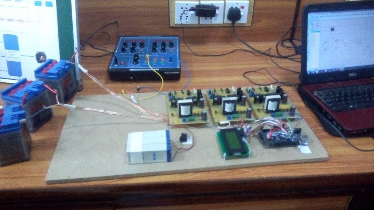
After the successful completion of our hardware on PCB, we started testing it. We met with a lot of issues as this was a Research and Development project. This projects is designed by students from UET taxila electrical engineering department. If you need complete circuit diagram and code of this project. Email me at microcontrollerslabhub@gmail.com.


Please send me complete circuit diagram and code of this project and proteus software files for multi input charger.
code is not for free. you can purchase it in 50$
hello sir i wanna get to know more about the project. let me know in detail
to tell the truth i have’t mony to buy the code. but i wanna to do this project . so pls help me sir?
I’m working on a self-charging EV and I’d like to work together with you.
Thank you