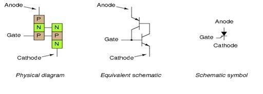
The silicon controlled rectifier (SCR) is a semiconductor device used to convert alternating current into direct current and control the power supplied to the load. It is an enhanced version of the shockley diode, achieved by adding a gate to the device. The SCR was developed in 1957 by power electronics engineers. Some consider the terms “thyristor” and “silicon-controlled rectifier” to be synonymous, while others believe that silicon-controlled rectifier is a specific type of thyristor. The SCR is a unidirectional device, unlike the bidirectional triac. Please refer to Figure 1 for the physical appearance, equivalent schematic, and schematic symbol diagram.
Silicon Controlled Rectifier Construction
The silicon controlled rectifier consists of three PN junctions which are labeled as J1, J2, and J3, and four layers of semiconductor materials joined in the form of NPNP and PNPN. In the PNPN type structure, the anode terminal is connected to the p-type material layer, while the cathode terminal is connected to the N-type material layer. Similarly, the gate terminal of the silicon controlled rectifier is connected to the P-type material layer, which is nearest to the cathode type material layer. The semiconductor material layers are formed by the diffusion of lightly doped semiconductor material into highly doped semiconductor material. The entire construction and junction diagram are shown in Figure 2.

Working
The silicon controlled rectifier works in three mode of operations
- Forward Blocking Mode
- Reverse Blocking Mode
- Forward Conduction Mode
Forward Blocking Mode
In this mode of operation, the anode terminal of the silicon control rectifier is connected to the positive terminal of the power supply, and the cathode terminal is connected to the negative terminal of the power supply. While zero voltage is applied at the gate terminal, in this condition, junctions J1 and J2 would be forward biased, and junction J3 would be reverse biased. Then, there would be a small current flow from the anode to the cathode, which is called leakage current. Due to this leakage current, the voltage across the anode and cathode increases until breakdown occurs between the anode and cathode. The voltage at which the breakdown occurs is called the breakdown voltage, and this mode is called the forward blocking mode.
Reverse Blocking Mode
In this mode of operation, the anode terminal is connected to the negative terminal of the power supply, and the cathode terminal is connected to the positive terminal of the power supply. In this mode of operation, the current also can’t flow from anode to cathode and block the voltage of this silicon control rectifier. Normally, the forward blocking voltages and reverse blocking voltages are almost the same.
Forward Conduction Mode
In this mode of operation, the anode terminal is connected to the positive terminal of the power supply, and the cathode terminal is connected to the negative terminal of the power supply. Positive pulse voltages are applied to the gate terminal. When these positive voltages are applied to the gate terminal, the silicon control rectifier is forward biased, and current flows from the anode to the cathode. This mode is called the forward conduction mode. Once it is forward biased, there is no need for any voltages at the gate terminal. It will remain in the on state until it is turned off. There are two ways to turn off this silicon control rectifier: either by reducing the gate current below the holding current or by shorting the anode and cathode through a transistor or a push button.
Types of Silicon Controlled Rectifiers
There are four main types of silicon-controlled rectifiers.
- 1 Reverse Conducting Thyristor or SCR (RCT)
- 2 Gate Assisted Turn-off Thyristor or SCR (GATT)
- 3 Gate Turn-off Thyristor or SCR (GTO)
- 4 Asymmetric Thyristor or SCR
Reverse Conducting SCR (RCT)
Normally, the thyristor conducts in the forward direction, but this type of thyristor conducts in the reverse direction because it has an integrated diode for this conduction. However, in the reverse direction, there is no facility to control the current or power. When it is conducting in the reverse direction, this device and the integrated diode do not conduct simultaneously. Therefore, not much heat is produced, allowing both the device and integrated diode to be cooled at the same time. This type of silicon control rectifier is often used in frequency changers and switching inverters.
Gate Assisted Turn Off SCR (GATT)
This type of thyristor is used in places where a fast turn-off process is required because sometimes a negative voltage is applied to the gate terminal to reduce the anode-to-cathode voltage. This negative voltage drains the minority carriers in the N-type region and ensures that the gate-to-cathode junction is not forward biased. The structure of this type is almost the same, with the only difference being the use of a cathode strip to increase the gate control of this type.
Gate Turn off SCR (GTO)
This type of thyristor is sometimes referred to as a gate turn-off switch, and this type is usually considered as a pure thyristor device. To turn off this type, only a negative voltage is applied to the gate terminal, and there is no need to turn off the anode-to-cathode voltages.
Asymmetric Thyristor or SCR
This type of thyristor is used in those places where the circuit does not experience any reverse voltages and does not require any rectifier capability. Therefore, in this type of thyristor, the junction J2 is much thinner than the other two, resulting in the N-type region providing a very low V-on voltage, which improves the turn-on and turn-off time of the thyristor.
Triggering Methods for SCRs
Triggering Methods for SCRs:
- Forward Voltage Triggering: In this method, the SCR is triggered by applying a positive voltage between the anode and cathode terminals. This causes the junction J1 to become forward biased, initiating the conduction of current through the SCR.
- Gate Current Triggering: One of the most commonly used methods to trigger an SCR is by applying a positive gate current. The gate terminal is connected to a control circuit that provides the necessary current pulse to trigger the SCR. When the gate current exceeds the threshold level, the SCR turns on and starts conducting.
- dv/dt Triggering: This method involves triggering the SCR by applying a rapid rate of rise of forward voltage (dv/dt) across the device. When the rate of change of voltage exceeds a certain threshold, it causes the device to turn on. Care should be taken while using this method, as excessive dv/dt can cause false triggering or damage to the SCR.
- Light Triggering: In this method, the SCR is triggered by exposing the light-sensitive silicon wafer to a rapid pulse of light. The light causes the generation of electron-hole pairs within the SCR, creating a path for current flow and triggering the device.
- Temperature Triggering: This method utilizes the change in temperature to trigger the SCR. When the temperature reaches a certain threshold, it causes the device to turn on and conduct current.
- Gate Assisted Triggering: In some cases, an auxiliary SCR or transistor is used to control the gate current of the main SCR. By controlling the auxiliary device, the gate current to the main SCR can be controlled, resulting in the triggering of the device.
Each triggering method has its advantages and suitability for specific applications. The choice of triggering method depends on factors such as the desired level of control, response time, and environmental conditions. It is important to select the appropriate triggering method to ensure reliable and efficient operation of the SCR.
Protection and Cooling of SCRs
Protection and cooling are essential aspects to consider when working with silicon-controlled rectifiers (SCRs) to ensure their reliable operation and prevent damage. Here are some important measures for protection and cooling of SCRs:
- Voltage Protection: SCRs have voltage ratings that should not be exceeded. It is crucial to use appropriate voltage protection devices such as voltage clamping circuits or transient voltage suppressors to protect the SCR from spikes or excessive voltage. This helps prevent SCR damage and ensures reliable performance.
- Current Protection: SCRs have current ratings that should not be exceeded. To protect the SCR from excessive current, it is important to incorporate current-limiting devices such as fuses, circuit breakers, or current-limiting resistors in the circuit. These devices help prevent overcurrent situations that can lead to SCR failure.
- Heat Sinking and Cooling: SCRs generate heat during operation, especially when handling high current levels. To prevent overheating and ensure efficient performance, proper heat sinking and cooling methods must be employed. This may include using heat sinks, which are metal components that help dissipate heat away from the SCR. Additionally, ensuring adequate airflow around the SCR and utilizing cooling fans or heat sinks with built-in fans can further enhance cooling efficiency.
- Thermal Protection: Monitoring the temperature of the SCR is important to prevent overheating and potential damage. Incorporating thermal protection devices such as thermal sensors or temperature switches can help detect excessive temperature levels. These devices can trigger alarms or shutdown the circuit if the temperature exceeds a safe threshold, protecting the SCR from thermal damage.
- Gate Protection: The gate terminal of an SCR is sensitive and can be susceptible to voltage spikes or transients. Using gate protection devices such as resistors, capacitors, or transient voltage suppressors can help protect the gate from unwanted voltage disturbances. This ensures stable operation and reliability of the SCR.
- Proper Wiring and Layout: The wiring and layout of the SCR circuit should be carefully designed to minimize interference and ensure proper grounding. Following best practices for wiring and layout can help reduce the risk of noise, voltage spikes, or unintended triggering, which can negatively affect the SCR’s performance and longevity.
By implementing these protection and cooling measures, you can enhance the reliability, efficiency, and lifespan of SCRs in various applications.
SCR Issues
The silicon-controlled rectifier (SCR) is a reliable and widely used semiconductor device. However, like any electronic component, it can encounter certain issues. Here are some common problems that can occur with SCRs:
- Shorted SCR: In some cases, an SCR might fail in a shorted mode, where it remains conductive even when there is no trigger signal applied to the gate terminal. This can result in continuous current flow, which can cause overheating and damage to the SCR and the connected circuit.
- Open SCR: An open circuit in the SCR occurs when the device fails in an open state, meaning it does not conduct current even when a trigger signal is applied. This can lead to a complete loss of functionality and no output from the SCR.
- Overheating: SCRs can generate heat during operation, especially when they handle high currents. If the heat dissipation is not properly managed, the SCR may overheat, leading to reduced efficiency, performance degradation, or even component failure.
- False Triggering: False triggering can occur when the SCR is unintentionally triggered by noise or voltage spikes in the circuit. This can lead to erratic operation and disruptions in the desired functionality of the controlled system.
- Insufficient Voltage Protection: SCRs have specific voltage ratings that should not be exceeded. If the circuit fails to provide proper voltage protection, the SCR can be subjected to voltage spikes or excessive voltage, leading to its damage.
To avoid or address these issues, it is essential to follow good design practices, such as ensuring proper voltage and current ratings, implementing adequate heat sinking and cooling methods, and providing effective protection circuits to prevent false triggering or voltage spikes.
Applications
The silicon controlled rectifier is used in different applications some which are listed below.
- AC Power Control: The Silicon Controlled Rectifier is a unidirectional device. When it is connected to the AC supply, it turns on in the positive half cycle of the AC supply and delivers power to the load. In the negative half cycle of the AC supply, it turns off and does not provide any power to the load. Therefore, it can be used for AC power control in power control switches such as fan dimmers, power regulators, and motor control, etc.
- Controlled Bridge Rectifiers: The Silicon Controlled Rectifier is used in AC to DC converters for the rectification of AC power into DC power, such as half-wave and full-wave rectifiers. The power of these rectifiers can also be controlled by giving the triggering signal at the gate of the SCR.
- DC Power Transmission: The Silicon Controlled Rectifier is used in DC power transmission lines for converting high-power AC into high-power DC.
- Power Electronic Devices: The Silicon Controlled Rectifier is used in power electronic devices for controlling the power of switching loads.
- The Silicon Controlled Rectifier is also used in different triggering timing and IC circuits.
You may also like to read:
interested