We will discuss how to use a microcontroller to generate sinusoidal pulse width modulation. We will explore the usage of SPWM signals as gating signals to the MOSFETs of an H-bridge in order to obtain a clean and precise sine wave output. By incorporating an LC filter, we can further enhance the quality of the sine wave. The technique of sinusoidal pulse width modulation is widely employed by inverter manufacturers and in various industrial applications to achieve a pure sine wave. It is also commonly utilized in online UPS systems for generating a clean sinusoidal output. Additionally, we will delve into the integration of these SPWM signals with an H-bridge configuration.
SPWM Introduction
Sinusoidal Pulse Width Modulation (SPWM) is a technique used to synthesize a nearly perfect sine wave from a pulse-width modulated (PWM) signal. It’s commonly used in power electronics and inverters to produce AC voltage or current waveforms that closely resemble pure sine waves.
SPWM is widely used in applications where generating a high-quality AC voltage is essential, such as in uninterruptible power supplies (UPS), variable-frequency drives (VFDs), and grid-tied solar inverters. The key benefit of SPWM is that it produces low harmonic distortion, making it suitable for driving sensitive loads and for interfacing with the grid.
Example
SPWM technique basically converts half of the sine wave into a small number of pulses, each having a different width. Sinusoidal pulse width modulation technique produces a pulsating wave in which the width of the pulses changes according to the amplitude of the sine wave voltage. For example, in a sine wave, the amplitude of the voltage is minimum at the start of the sine wave at 0 degrees, and then it starts increasing up to 90 degrees where the sine peak amplitude is reached. After that, the amplitude starts decreasing again in a reverse fashion as it increased. In the SPWM technique, we follow the same procedure to make a pulsating waveform in which the width of each pulse varies according to the same fashion as followed by the sine wave magnitude.
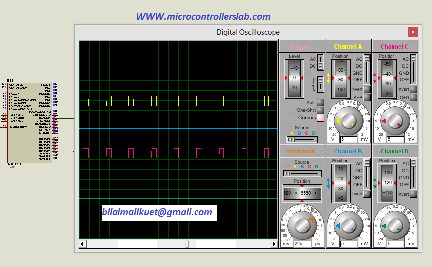
{ 1,2,3,4,5,6,5,4,3,2,1}Above data shows the maximum duty cycle or width of the pulse is 6, and then it starts decreasing in reverse as it is increased. The figure below shows the pulses of SPWM.
Methods to Generate SPWM
There are two ways to generate SPWM:
Analog Method
Here’s how SPWM generation works in analog method:
Reference Sine Wave: In SPWM, you start with a reference sine wave, which represents the desired output waveform. This reference sine wave has the same frequency and amplitude as the desired AC signal.
Comparison with a Carrier Signal: A high-frequency carrier waveform is generated, typically a high-frequency triangular or sawtooth wave. This carrier signal serves as a time reference.
Comparison: The reference sine wave is compared with the carrier signal. The comparison process involves continuously comparing the instantaneous amplitude of the sine wave with the instantaneous value of the carrier signal.
Pulse Width Modulation (PWM): The comparison results in a pulse-width modulated (PWM) signal. The width (or duration) of each pulse is determined by the comparison between the reference sine wave and the carrier signal. The pulse width varies to match the amplitude of the reference sine wave at each instant.
Gate Control: The PWM signal controls the gates (switches) of power electronic devices, such as transistors or MOSFETs, in an inverter circuit. These devices switch the DC voltage on and off to generate an AC voltage.
Output Synthesis: The switching of the power devices according to the PWM signal generates an AC-like voltage at the output. By carefully adjusting the pulse widths based on the reference sine wave, the output waveform closely resembles a sine wave.
By using microcontroller or digital electronics.
This method is preferable and is used in almost all pure sine wave inverters available in the market because it is cheap and easy to implement. All we need is a piece of information, i.e. code, to implement SPWM through this technique. The same microcontroller can also be used for other functions in the inverter, like protection, voltage and current reading, digital display of current and voltage, and any other functionality we want to have in our inverter. It is the reason we always prefer microcontrollers or digital electronics over analog electronics. It makes our lives easier by adding extra functionality to our project. In this article, we will also discuss how to use PIC16F877A to generate SPWM.
Steps to implement SPWM with a microcontroller
Initialize the Microcontroller: Set up the microcontroller’s clock source and configure any necessary peripherals like timers, GPIO pins, and the PWM module.
Create a Sine Wave Table: Create a table that contains discrete values representing one complete cycle of a sine wave. The number of entries in the table determines the resolution of the SPWM signal. The table should span 0 to 2π radians (or 0 to 360 degrees) and should include values that closely approximate a sine wave.
Generate PWM Signal: In your code, you will use a timer to control the PWM signal. The timer’s period (time for one cycle) will determine the frequency of the SPWM signal. The duty cycle of the PWM signal will be adjusted to generate the desired SPWM.
Calculate PWM Duty Cycle: In the interrupt service routine or periodically within your code, calculate the appropriate duty cycle for the PWM signal based on the desired amplitude of the sine wave at that point in time. You can use the sine wave table for this purpose.
Output PWM Signal: Set the PWM duty cycle to control the PWM output pin. The PWM signal should vary according to the values in the sine wave table to approximate a sine wave.
Loop and Repeat: Continuously update the PWM duty cycle to generate the entire SPWM signal.
Here’s a simplified code snippet for implementing SPWM on a PIC microcontroller:
#include <xc.h>  // Include the XC compiler library for PIC

// Define the sine wave table
const unsigned int sineTable[] = { ... };  // Populate with sine wave values

void main() {
    // Initialize the microcontroller and PWM module
    // Configure the timer for PWM generation

    while (1) {
        // Calculate and set the PWM duty cycle using values from the sine table
        // Adjust the delay to control the frequency and phase of the SPWM signal
        // Update the PWM output
    }
}
SPWM implementation using PIC16F877A microcontroller
Before implementing SPWM with a microcontroller, you should know the frequency of the sine wave you want to generate. In this project, I have used a 50 Hz frequency. A 50 Hz frequency means the time period of the sine wave is 20 ms. Therefore, the time period for half a cycle is 10 ms, as we generate only half a cycle that is used for both the positive and negative cycles. The H bridge serves the purpose of generating the negative or positive cycle. SPWM for half a wave contains multiple pulses, and the width of each pulse varies according to the amplitude of the sine wave. However, the total time of all the pulses should be equal to 10 ms, the time period of half a cycle of the sine wave. But the question is, what should be the time period of each pulse? The time period of each pulse depends on the frequency of the PWM. For example, if we have
Number of pulses = 10ms / 100us =100 pulses.Example
We can use 100 pulses for SPWM with a 20 kHz frequency. We have already explained the functionality and working principle of SPWM. Now, we will explain how to generate 100 pulses with variable width or duty cycle according to the amplitude of the sine wave. We know the relationship of the sine wave with its phase angle and peak value. y = A * sin(angle). We also know that a half cycle of the sine wave consists of 180 degrees. For example, if we need 10 pulses, we divide 180 degrees into 10 equal parts. To achieve this, each step would be 180/10 = 18 degrees.
- Y = sin (18) = .3090
- Y= sin (36) = .5877
- Y = sin (54) = .8090
- Y = sin (72) = .9511
- Y = sin (90) =1
- Y = sin (90) =1
- Y = sin (72) = .9511
- Y = sin (54) = .8090
- Y= sin (36) = .5877
- Y = sin (18) = .3090
To convert the above values into a duty cycle, multiply them by the maximum duty cycle value that a microcontroller uses to generate the duty cycle. In the PIC16F877A, the duty cycle ranges from 0 to 255, where 0 represents a 0% duty cycle and 255 represents a 100% duty cycle. I recommend multiplying by a value less than 255, as it will help you avoid the gate turn-on or turn-off time circuitry. This will introduce a delay between the turn-off and turn-on of the MOSFETs in the H-bridge configuration.
- Y’ = sin (18) = .3090 * 250= 77
- Y’= sin (36) = .5877 *250=147
- Y’ = sin (54) = .8090 *250=202
- Y’ = sin (72) = .9511 *250=238
- Y’ = sin (90) = 1 *250=250
- Y’ = sin (90) = 1 *250=250
- Y’ = sin (72) = .9511 *250=238
- Y’ = sin (54) = .8090 * 250=202
- Y’= sin (36) = .5877 *250 =147
- Y’= sin (36) = .5877 *250= 77
Hence, the duty cycle or width of each pulse is {77, 147, 202, 238, 250, 250, 238, 202, 147, 77}. Similarly, you can calculate the duty cycle or pulse width for 20, 30, 100, or any number of pulses you want to use in your SPWM. The greater the number of pulses, the more pure sine wave will be produced. I have explained everything you need to know about sinusoidal pulse modulation: how to choose the number of pulses, how to calculate the width of each pulse, and what the relationship is between the time of total pulses and the timer of half the cycle of the sine wave. Now you can develop an algorithm using any microcontroller to generate SPWM. I have used the PIC16F877A microcontroller to generate SPWM with 100 pulses and a frequency of each pulse of 20 kHz. The frequency of the output sine wave is 50 Hz.
Steps to Write Algorithm
- Make an array containing duty cycle values of each width
- Generate a PWM of frequency 20 KHz
- call each in a function such a way that it repeat itself after a complete cycle.
This is all you need to do with a microcontroller to generate SPWM. For more information about how to write code for SPWM using the PIC16F877A microcontroller and how to use SPWM for producing gating signals for an H-bridge, as well as the complete circuit diagram of a pure sine wave inverter, please refer to the following article.
Conclusion
In conclusion, sinusoidal pulse width modulation (SPWM) is a powerful technique used in power electronics and inverters to generate high-quality AC voltage waveforms that closely resemble pure sine waves. By using SPWM, it is possible to achieve low harmonic distortion and produce clean and precise sine wave outputs. The implementation of SPWM can be done through analog methods or by utilizing microcontrollers and digital electronics. The use of a microcontroller offers advantages such as flexibility, cost-effectiveness, and the ability to incorporate additional functionalities. By following the steps outlined in this article, it is possible to generate SPWM signals using a microcontroller like the PIC16F877A and achieve a pure sine wave output. Overall, SPWM is widely employed in various industrial applications and is an essential technique for producing high-quality AC voltage waveforms.
You may also like to read:
- Soft starter for 3 phase induction motor using Arduino
- Variable Frequency Drive 3 phase Induction Motor using Pic Microcontroller
- three phase variable frequency SPWM for VFD using pic microcontroller
- three phase sine wave inverter using pic microcontroller
- Three phase space vector pulse width modulation using pic microcontroller
- single phase pure sine wave inverter using arduino
- Pure Sine Wave Inverter using PIC Microcontroller
can you explain the programme in details pls
sir, I wana to make 3 phase inverter , which voltage and frequency should vary as per the v/f ratio, 0-50hz.
I wana to make 3 spwm each have 180 degree apart.
can I use aurdino (atmega328), can I generate 3 spwm by hardware,
pls help me
if you have gotten the answer then please help me doing this….
Very nice blog u got here
But this means I cannot use the microcontroller for other purposes such as PID control calculations while generating SPWM, right?
thank you sir .thank you very much…………..
can i use this spwm for controlling single phase ac induction motor control.
can u explain the program in detail
i have studied this topic from various books and researching it on internet for 2-3 years to get the complete understanding and its implementation .Today my search ends .your one page article gave more information and in very simple way compared to 2 or 3 prescribed UG engineering books.
Thanks a lot.
Mikro c(pic16f877a)
sir how generate 12 gating signals…
sir hw to generate 12 gating signals….
I would like to see a picture of what is in the mosfet because much of what you have to prove to me it does not generate a pure square wave and I would like to know how often you calculate the lc filter
sir can the explain the code in detail plz..
sir can u explain the code in detail plz..
sir,can u explain the code in detail…
Sir,I hv connect the ckt in breadboard.I hv downloaded program in pic IC. But output at pin no 34 n 17 it not cmg.I hv given 5v dc supply .plz Help me…
Hi
I have sin very good projects in here and would like some help from you….
I got a project to design and implement…. the project is
12v DC /220v AC micro controller base to produce PWM…..
500w output power to use for sensitive electronic devices
the problem is I run out of time for the project….
And now I am really struggling ho to make it… the design to determine the right components
can you help me please?
hi! I i trying to design a Sine Wave Inverter but i have some broblem. i cant see signal output on RB1.it nothing. can you give me code it ?. iguess i fail when i copy.
my email: chimchichclick@gmail.com
hi sir,Could you please give us the programme of this PWM in protus ISIS because I will make a three phase inverter plz help me
Dir Sir,
I appreciate so much your work …
Could you please explain to me please how we get a pulse time periode of 100us for a 20khz frequency unless we got a frequency pf 10khz instead. Am i right.
Thank you in advance.
Sincerly
I want to generate R-y-B 3 phase sine wave using PWM technique in PI18F. how should i calculate the value of look up table?
Can I have get the code in CCS C compiler.
i can’t open this page 404 error PLz can support me in this problem
“Complete circuit diagram of pure sine wave inveter and coding”
Can you Generate SPWM without CCP. Only using GPIO Pin.
Hello,me I am having a problem of using this IR2110 for driving 6 IGBT s making up a three phase IGBT bridge for three phase induction motor speed control,could anyone help me to handle this issue?I am using PIC16F1936 for generating the six signals but I am not succeeding please help.
What kind of problem you facing in driver.?
Comment Text* what calculation did you do, that resulted in getting the period of each pulse as 100us. I am a bit confused about it.
Good job sir but there is a little confusion, which is ; what calculation did u do ,that resulted to getting the period of each pulse as 100us ? I would be so grateful if u can answer as soon as possible.
sir please i need a complete pure sine wave inverter circuit using any of the pic 16 series micro controller with the source code
Dear Bilal Malik:
I read your tutorial on using PIC 16F877A SPWM Implementation microcontroller and is a very good help for this purpose.
In its description you say, referring to a sine wave of 50 Hz “But the question is what Should be the time period of each press? Time period of each press depend on frequency of PWM. For example We Have Chosen to PWM of frequency 20 kHz. HENCE Time period of each press is equal 100us. So we can number of pulses used to make SPWM is equal to
Number of pulses = 10ms / 100us = 100 pulses.
Question ? If the PWM frequency is 20KHz we use, its period is 1 / 20,000 = 50us and if we consider only half cycle, the number of pulses is:
Number of pulses = 10ms / 50us = 200 pulses
Please clarify my doubt answering my mail.
Thank you
what did you multiplied 255 to instantaneous sine values???
8 bit timer is cable of producing 0-255 duty cycles (8 bit 2^8=255)
sir can you explain code please
Hence Time period of each pulse is equal 100us. So number of pulses we can used to make SPWM is equal to
Number of pulses = 10ms / 100us =100 pulses.
How did you get this 100us
THANKS A LOT ,THIS PAGE IS MORE THAN BOOK,
Very useful, specially in calculating duty cycle of each pulse for sine PWM
very useful article…
but can we calculate the amplitude modulation of SPWM?
much appreciated 🙂
Thank you so much. This explanation was more important for my understanding about this theme. SPWM in analog circuits is very easy but digital visualization was difficult. Thank you man. God bless you.
Dear Bilal:
I like electronics and I intend to build a SPWM of 100 W to start testing and therefore I read all the information that you periodically publish. However, I find a point that does not allow me to move forward since I do not understand a part of your publication and it is the following:
If the output wave I want to obtain is 50 Hz and the chosen PWM frequency is 20 Khz, the period of each pulse is 100 us.
Please explain how you get this period of 100 us or tell me some reading text.
My email is jmimbelac@yahoo.es
Thank you
Hello sir,
Can we able to generate 80Khz pwm from PIC 16F877A and my crystal frequency is 16MHz
yes it is possible I can do it for you contact me at microcontrollerslabhub@gmail.com
Hello sir,
I need four pwm signals in my project ,so is it possible to have four PWM signals from a single 16F877A MICRO CONTROLLER? I came to know that it has only two ccp module and is it possible to extend??
Dear Sir please clarify my doubt. I want to generate sine wave of frequency 50hz. So it is necesaary that the frequency of spwm is also 50hz? And if not then how to find the suitable frequency of spwm for sine wave having frequency 50 hz.
First of all I would like to thank you for your useful explanations.
But, Would you please express more “How did you calculate Time period for 20KHz”?
(Confusion about 100uSec , Because Tpulse = 1/20KHz = 50uSec not 100uSec)
Hello and thanks for very useful explanation
can you please explain about ARM base invertors
and its code and cube ide of it
thanks a lot