This project is about three phase sine wave inverter using pic microcontroller. Three phase sine wave inverter is designed using pic microcontroller. Three phase sine wave inverter projects has many application in power electronics field. Three phase sine wave inverter is used to convert dc power supply or dc power source or dc voltage from battery into three phase ac supply. There are many applications where three phase supply is required. For example, three phase induction motor or three phase induction motor speed control. For example if you have access to single phase power supply from your electric power company and you want to run three phase load with it. you will need a device which can convert single phase power into three phase power.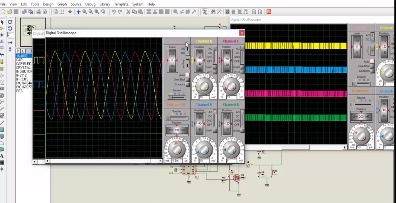
In that case, you need to convert your single phase power supply into dc power. After that you can convert this dc power into three phase ac power using three phase sine wave inverter. Another application of three phase sine wave inverter is in solar power system. As you know solar panels give in direct current form. If you want to use solar power to fed devices which operates on ac power supply. you will need a dc to ac converter which is also known as inverter. Similarly you can also convert this dc power of solar panels into three phase ac power using three phase sine wave inverter using pic microcontroller or any other microcontroller like Arduino. I have already posted a article on three phase sine wave inverter using Arduino mega. If you want to design three phase sine wave inverter using Arduino, you can also check it. You may also like to check my other inverter related project:
- Single phase sine wave inverter using Arduino
- Single phase sine wave inverter using pic16f877a microcontroller
- Single phase sine wave inverter using dspic microcontroller
- SVPWM generation using pic microcontroller
Working of three phase sine wave inverter using pic microcontroller
Video below shows the working simulation of three phase sine wave inverter. In this project PIC6F877A microcontroller is used to generate sinusoidal pulse width modulation signals. These SPWM signals are 120 degree out of phase with each other. These SPWM signals are given to three phase H bridge through MOSFET driver IR2110. If you don’t know how mosfet driver works and how to design H bridge using IR2110 MOSFET driver, you can check these articles:

These SPWM signals are used to drive three phase H bridge in such way that H bridge produces three pulsating signals which are 120 degree out of phase with each other. At the output of three phase H bridge, LC filters are used to get pure sine wave. For more about the working of three phase sine wave inverter using pic microcontroller, check the simulation
If you want to make this project on real hardware, you can simply made the schematic given in simulation and upload code to pic microcontroller and it will surely work fine for you.
i like this project
Sir want to purchase this preoject give me your contact number
pls i need to how to read ac voltage with lm324 on mikroC
we can not measure ac voltage directly with lm342.
let me know your complete specification so that I can help you
you can check these articles
http://microcontrollerslab.com/ac-voltage-measurement-using-microcontroller/
http://microcontrollerslab.com/ac-voltage-measurement-arduino/
Generation of a 3-phase waveform using a 16f877a microcontrolle ineed thes
Sir want to purchase this preoject give me your contact number