In this tutorial, we will look at the workings of subVI. A subVI is the same in LabVIEW as a function or subroutine in a text-based programming language. At the start, we have provided an introduction to a subVI, including their needs and uses. After that, we will design an explanatory VI, which will use a subVI, and discuss some different features of the subVI as well.
Introduction to SubVI in LabVIEW
We can define subVis in LabVIEW as modularity. This means using smaller modules or smaller parts for the overall objective, collectively doing the same tasks as the bigger project. We call creating smaller sections of our overall code a subVI, and in LabVIEW, we can refer to it as program modularity. In LabVIEW, there is not much difference between a VI and a subVI; they are similar to each other. Each sub VI is composed of its own block diagram and its own front panel, but we can only access a sub VI by calling it in its parent VI.
An icon can be seen within the VI, representing the subVI. This is created along the subVI within a VI. This icon can be customized; the icon for a subVI is the same as in the upper right corner of a simple VI block diagram and front panel window. Customizing an icon is also explained in a later section of the tutorial.
Functions or Subroutines
Those who are familiar with C or any other text-based programming language must know terms like classes, functions, and subroutines. The purpose of a subroutine is simply to do a larger task in smaller portions. If we want to build a project using microcontrollers, we can write one function to initialize timers and use another to implement the main program, whereas both of them are called in the main function.
Now, we will translate this into the language of LabVIEW. The timer initialization and main function implementations are done in subVI; however, both of them are called in the main VI of the program. In the following program, we will explain the workings of subVIs.
Example of SubVI in LabVIEW
Moving to the programming part, create a VI as we have done in Tutorial 1 and save it for future use, similar to all the previous tutorials.
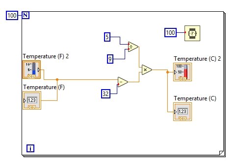
To understand the use of subVIs, what we have to do is first design a larger program that we want to convert into modules or subVIs. To save our time, let’s use the VI we have already created in the graphs and charts tutorial. The one in which temperature is converted from the Fahrenheit scale to the Celsius scale, as shown in the figure below.
Creating SubVI
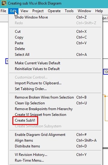
From the top bar, when we click on the Edit button, a dropdown will appear. In this dropdown, the Create SubVI option is present, as shown in the figure below.
Select the area of the code or block diagram from the complete VI that you want to put inside the subVI; for reference, see the figure below.
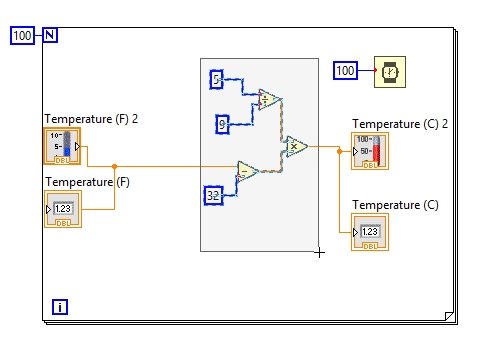
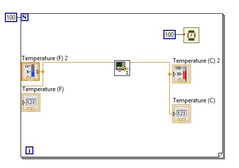
In the above figure, we want to create a subVI in which the blocks inside the selected portion will appear, and in place of this selected portion, only an icon will appear. This icon represents the presence of a subVI. See the figure below.
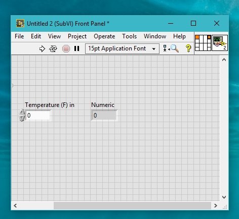
Front Panel of SubVI
When we double-click on the icon shown in the figure above, a different front panel will appear, as shown in the figure below.
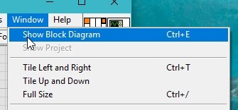
We can also see the block diagram of subVI using the top bar. Firstly, click on the Window and select Show Block Diagram, as shown in the figure below.
The block diagram of subVI will appear as shown in the figure below.
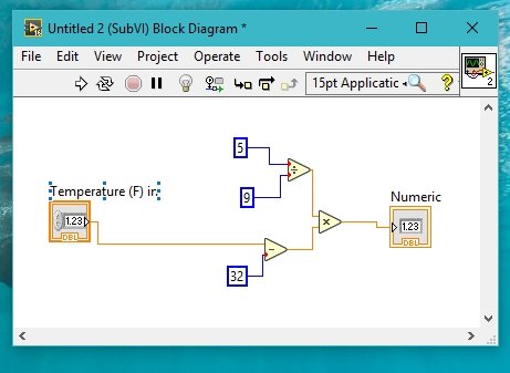
From the above figure, we can see that this is the same as the blocks we selected for the creation part of the subVI.
One good thing about using subVI is that we can modify them to add some additional functionality. Let’s say in this code we want to modify the conversion. i.e., we want the user to decide whether he wants to convert the temperature from Fahrenheit to Celsius or whether he simply wants to display the temperature as it is.
This is the same task as we have done before in the case structure tutorial. In this case too, we will use a case structure with a button to decide which case to use.
Placing Case Structure in SubVI
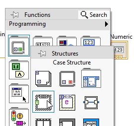
In the subVI, place a button on the front panel to toggle the user’s decision. Also from the Function Palette, select a Case Structure from Structures. Now, place all the blocks in that structure, as shown below.
After selecting the case structure, select the area to place it, as shown in the figure below.

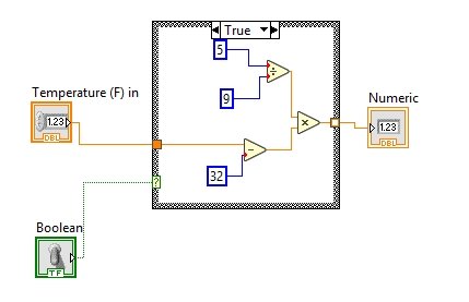
The true condition of the switch will return the converted scale of temperature, i.e., from Fahrenheit to Celsius, as shown in the figure below.
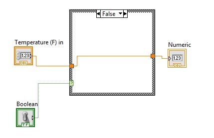
The false condition of the switch will return the temperature in Fahrenheit, as shown in the figure below.
Properties Icon in SubVI
Now, the point is that the switch present in the subVI cannot be operated from the main VI right now. How do we make a connection for this switch in the main VI? In the upper right corner of the subVI, there is an icon similar to the icon present in the main VI, as shown in the figure below.
The matrix with orange in it represents two terminals of subVI, i.e., the input and the output terminals. If we want to add another terminal to it, as we want right now for a toggle switch, click on any of the blocks, and they will turn black as shown below.

Now click on the toggle switch, and this slot will turn green because the switch is a Boolean, and the green color also represents a Boolean, as we have discussed in previous tutorials. Refer to the figure below.

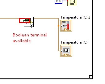
Now, if we check the main VI, we can see that a Boolean terminal is also present on the subVI icon, as shown in the figure below.
Block Diagram
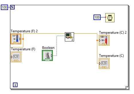
Right-click on this terminal and create a control on it, as we have done in previous tutorials. The complete block diagram is shown in the figure below.
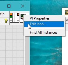
Lastly, we can also customize the icon of the subVI by right-clicking on it. Then select the Edit Icon, as shown below.
Exercise
Design a sub VI that will take two integer inputs and return 4 outputs, i.e. their sum, product, quotient, and subtracted value.
Conclusion
In conclusion, this tutorial provided a comprehensive overview of subVI in LabVIEW. SubVIs, also known as program modularity, offer a way to create smaller sections of code for better organization and reusability. The tutorial explained how to create a subVI by selecting and encapsulating a portion of code within an icon. It demonstrated how to customize the subVI’s front panel and block diagram, as well as how to add additional functionality such as a case structure. Furthermore, the tutorial highlighted the properties icon and how to add terminals for data exchange between the subVI and the main VI. Lastly, an exercise was provided to design a subVI for performing arithmetic operations. Overall, this tutorial serves as a valuable resource for those looking to leverage the power of subVIs in LabVIEW to enhance their programming workflow.
You may also like to read
- SEPIC Converter Proteus Simulation
- Arduino Uno Introduction, Pinout, Examples, Programming
- Simulation and design of Three phase Rectifier in Simulink MATLAB
- DC Motor Control with LabVIEW and Arduino – Tutorial 3
- Telegram Control ESP32 and ESP8266 GPIOs and LEDs using Arduino IDE
- Reconnect ESP32 to WiFi after Lost Connection (Solved)
This concludes today’s article. If you face any issues or difficulties while following this tutorial, let us know in the comment section below.