DC to DC converter using push-pull topology: DC to DC converters have vast applications nowadays in switch-mode power supplies, AC motor drivers, DC motor drivers, and inverters. The objective of this project is to convert 12-volt DC into 311-volt DC, which is a peak of 220 AC voltage. Push-pull topology is used because of its high power handling capability than buck, boost, and buck-boost converter. I have already explained pulse width modulation and the use of the SG3525 IC because I have used SG3525 as a PWM controller IC in this DC to DC converter. Other components used in this project are ferrite core transformer, rectification circuit, and feedback circuit.
If you don’t know how to use voltage mode PWM controller IC SG3525.I recommend you to go through following article first before reading this article further: SG3525 Pulse width modulation controller IC
Push-Pull Topology Introduction
Push-pull converter is similar to a buck converter, but it has two drive winding isolation transformers. I will explain how to make a high-frequency transformer later. It can be used for step-up or step-down purposes depending on the turns ratio of the high-frequency transformer. The push-pull topology requires a smaller filter compared to other DC-to-DC converter typologies. Multiple outputs can be produced by winding the high-frequency transformer according to the application. You just need to increase the number of output windings in proper relation to the turns ratio with the primary turns of the high-frequency transformer.
High frequency transformer
High-frequency transformers of push-pull DC-to-DC converters can handle more power than forward converters. This is because push-pull converters operate in two quadrants of the B-H curve, whereas forward converters only operate in one quadrant of the B-H curve. If you are unfamiliar with the B-H curve, I recommend studying it from any power electronics book.
High-frequency Transformer Turns Ratio Calculation
High-frequency wound transformers are usually not available in the market. Ferrite cores are available in the market. You have to wind them according to your specifications. For example, in our project, we want to convert 12 volts DC into 311 volts DC. We can calculate the turn ratio for the ferrite core by using the input and output voltage. There is a proper relationship that exists to calculate the turn ratio for a ferrite core transformer. There are many ferrite core shapes available according to their power handling capability. For example, we are designing a 200-watt DC to DC converter. The ETD39 core will work fine in this range of power. If you want to study more about ferrite core selection according to its power handling capability, I suggest you study “Practical Switching Power Supply Design” by Marty Brown, Chapter 6.
We can easily calculate primary and secondary turn by using following formula:
N (primary) = (Vin * 10^8) / ( 4 * f * Bmax * Ac )
- Vin is a input voltage that is voltage which we want to step up in our case
- f is a switching frequency of dc to dc converter.In our project switching frequency is 49kHZ. I will discuss it in detail later.
- Bmax is maximum flux density. It depends on the core you are using. You can check its value limit from data sheet of core you are using. Bmax value should be with in a limit. Very high value cause a core to saturate and too low value will not utilize core properly. After reading from various books and sites, maximum authors suggest to use it value between 1500-1600 gauss.
- Ac is cross sectional area of core you are using in your project.you can get its value from core data sheet.In this project we are using ETD39 hence Ac value given in its data sheet is 1.25 cm^2.
Equation
Hence by using above formula and values one can easily calculate Primary turns. Secondary turns can be easily calculated by using turns ratio formula of transformer that is :
turn ratio = primary voltage / secondary voltage
turn ratio = primary turns / secondary turns
By using primary and secondary voltage we can calculate turn ratio. By using turn ratio and primary turn we can easily calculate secondary turns. But in push pull topology high frequency transformer, There are two primary winding so primary turns will remain same for both primary winding.For example we have calculated 3 primary turns. Then total primary turn will be 3 turns + 3 turns for each primary. Figure below shows push pull transformer:

Components
List of components:
Resistors,"R1",470k,
Resistors,"R2",10R,
Resistors,"R3",10R,
Resistors,"R4",1k,
Resistors,"R8",1k,
Resistors,"R9",1k,
Resistors,"R11",1k,
Resistors,"R5",2.2k,
Resistors,"R6",22R,
Resistors,"R7",15k,
Resistors,"R10",56k,
Capacitors,"C1",68nF,
Capacitors,"C2",10nF,
Capacitors,"C3",1nF,
Capacitors,"C4",1uF,
Capacitors,"C5",220uF/400v,
Integrated Circuits,"U1",UC3525,
Transistors,"Q1",IRF3205,
Transistors,"Q2",IRF3205,
Rectifier diode,"BR1",UF4007,
switch,"SW1",SW-SPST,
Ferrite core transformer
battery"V1",12V,
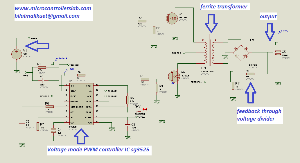
Circuit Diagram of Push pull DC to DC Converter
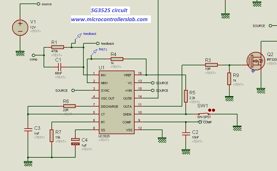
The circuit diagram shown above is a DC to DC converter using a push-pull topology. It is designed to convert a 12-volt DC input voltage into a 311-volt DC output voltage. The circuit utilizes the SG3525 PWM controller IC to control the switching of MOSFETs, which in turn regulate the output voltage.
The circuit diagram demonstrates the connections and arrangement of these components to achieve the desired DC to DC conversion. The SG3525 PWM controller IC generates the necessary pulse width modulation signals to control the switching of the MOSFETs, ensuring efficient power conversion. The ferrite core transformer plays a crucial role in stepping up the voltage level.
Working
Here’s a step-by-step explanation of the working of this push-pull DC-to-DC converter:
Input Voltage: The input voltage, which can be from a DC source such as a battery or a power supply, is connected to the circuit.
Oscillator (SG3525): The heart of this circuit is the SG3525 PWM controller. This IC generates a high-frequency PWM signal that is used to control the switching of the power transistors.
Comparator and Error Amplifier: The SG3525 has an internal error amplifier and a comparator. The error amplifier compares the reference voltage (set by the voltage divider formed by R2 and R3) with a feedback voltage derived from the output. The comparator compares the error amplifier’s output with a triangular waveform generated by the internal oscillator.
PWM Generation: Based on the comparison results from the error amplifier and comparator, the SG3525 generates a PWM signal with a variable duty cycle. The duty cycle controls the time for which the power transistors are on and off.
Power Transistors (Q1 and Q2): The PWM signal from the SG3525 controls two power transistors, Q1 and Q2. These transistors are arranged in a push-pull configuration. When one transistor (e.g., Q1) is on, the other (Q2) is off, and vice versa. This push-pull action allows the circuit to switch current through the primary winding of the transformer (T1).
Transformer (T1): The primary winding of the transformer receives the switched current from the power transistors. This switching creates a changing magnetic field in the transformer core, which induces a voltage in the secondary winding.
Output Rectification and Filtering: The secondary winding of the transformer is rectified using diodes (D1 and D2). The resulting pulsating DC voltage is smoothed using an output capacitor (C2) to obtain a relatively stable DC output voltage.
Feedback Loop: The feedback voltage from the output is compared to the reference voltage. If there is a difference, the error amplifier adjusts the duty cycle of the PWM signal to maintain the desired output voltage.
Output Load: The regulated DC output voltage can be used to power various loads or charge a battery, depending on the specific application.
The primary function of this circuit is to efficiently convert the input DC voltage to a regulated output voltage by adjusting the duty cycle of the PWM signal. The SG3525 controller continuously monitors the output voltage and adjusts the switching of the power transistors to maintain a stable and regulated output voltage, even under varying load conditions. This makes it suitable for various power conversion applications, such as DC-DC converters, inverters, and battery chargers.
Conclusion
In conclusion, the push-pull topology based on the SG3525 PWM controller IC offers a reliable and efficient solution for converting 12-volt DC into 311-volt DC, making it suitable for various applications such as switch-mode power supplies, motor drivers, and inverters. The high-frequency transformer used in this topology enables higher power handling compared to other DC-to-DC converter typologies. By following the recommended calculation methods and selecting the appropriate components, it is possible to design and build a stable and robust DC to DC converter. For further information, references, and related projects, please refer to the additional resources mentioned in this article.
You may also like to read:
It was very interesting to study your blog can you please send the simulation file to my email.
thanks and keep visiting my blog for more articles on power electronics and embedded system.
Post your email address in comment to get simulation of dc t dc converter using push pull topology ..
Good luck
Bilal…………can you tell me about the gauge of wire which you used in your project and what’s primary voltage across (primary of chopper)………….in your project and how can i calculate the Bmax……..i am working on the same project as well (final year)
hi dear.thank u for your good site. please send me your simulation
thank u very much
Circuit diagram is available in above article and thanks
hello mr bilal i hope u send me your simulation of pushfull converter
Bilal can this circuit be used for stepping down 200V dc to 10V dc rating(10A),and in proteus specifications asked are primary inductance and secondary resistance ,how turns ration be related to that which i have calculated by formulas given by you? .Secondly UC 3525 is not available in proteus,how that can be tackled ,If you send me this simulation i will be thankful
http://www.4shared.com/file/4FypbHggba/push_pull_converter_simulation.html?
use this link to download simulation
unable to download the simulation model.please help me….
This is very informative kindly provide me simulation file of this circuit. I will be very thankful to you
Great Work Bilak,
I am very interested in your design, I am looking to implement something similar. Can you please provide more details on the winding of the trasnformer in terms of AWG used and winding method. Can you also comment on the core imbalance inherent in the design of push-pull topology.
Once again great work, and thanks for sharing. Something I believe in greatly.
Regards Peter.
Bilal………..can you tell me the gauge of wire which you used in your project in (chopper) and what’s voltage across the primary of chopper at that time and finally, how can i calculate the Bmax? reply
Salam bilal,
I just loved reading ur blog it was really helpfull .. i tried constructing the push pull topology u shown in schematic . everything was going fine till i struck when i placed tranformer in proteus .. its showing transient error .. can u plz help me debuging this? it will be kind of you. thanku keep posting such blog 🙂
Salam bilal,
I just loved reading ur blog it was really helpfull .. i tried constructing the push pull topology u shown in schematic . everything was going fine till i struck when i placed tranformer in proteus .. its showing transient error .. can u plz help me debuging this? it will be kind of you. thanku keep posting such blog 🙂 ..thanks in advance
I think issue is with your transformer library of Proteus
Hi Bilal,
Great works going here. Thank You.
Here is my doubt.
People usually say no to have a common ground (I mean H bridge isolated from the push pull part)
But here in this circuit it seems to me like it’s a common ground. I would like to know if there is any serious issues that you are facing?
Regards
What is meant by 10R as the value of resistor?
Nice to go through your blog and got good understanding of DC -DC converter & transformer winding details.
Can you please send the circuit diagram and simulation of the project.
circuit diagram is given in article
Hi Bilal
i have asked this question of you more than two weeks ago and have had no response. Please help me.
I am needing to make a 1200 – 1500W sine wave inverter and have studied your articles in this regard in the finest detail. I wish to use an Arduino uno to achieve this using all your advice which is much appreciated.
My problem that I have lies in the core selection for the DC-DC conversion for this power conversion. My dilemma lies in what is probably a lack of understanding of your circuit. I am aware of the voltage feedback you are using with the IC to alter the PWM in order to stabilise the output voltage under varying loads and input voltage variances. What concerns me is how you prevent ” Flux walking” or transformer core saturation, as a result of any probable dc bias. I have tried all sources for a solution that I can understand however they all seem a little out of my grasp with my limited experience, the most interesting reading being found here http://powerelectronics.com/power-electronics-systems/special-dcac-inverter-avoids-transformer-core-saturation
Any light that you could shed on this problem will be most appreciated.
Kind regards
Bruce
Reply
Great article, keep it up
Great article, please send me the complete circuit diagram
Kindly sent me your complete circuit diagram and simulations on email id. Thanks !
cjo0ololo0o@gmail.com
Kindly sent me your complete circuit diagram and simulations thanks Sir
It is given in article. Simulation is not free you can purchase it
Hi bilal,
I have seen your explanation about the sg3525 inverter. these modules are for sail now on ebay and i would like to know how I can put two of these modules in parallel. and connect them to a post sine wave board of 1Kw. I see that you can sync the chips using the Sync (pin3) input but I do not know what the exact criteria is. I hope it is possible to sync one chip to the other by available signals but am not sure. An other possibility is to connect the bridge rectifiers together and that is. Can you help me with this regards Oscar Goos (wogoos@gmx.com)
How many MOSFET required for 3000 Watt
hi bilal
in my project we use dc to dc converter which convert 24 v to 360 v and 500 w what should i do if i use your circuit.
thank you for you great effort.
I’ll appreciate sending me the design files.
Regards,
good work malik.
I have two questions on ferrite core transformers
1. suppose I want to use a 500W ferrite core transformer, how do I know the part number? and is there a single 1000W ferrite core? if there is, how do I know it’s secification.
2. how do I know the specifications (ie power rating, permeability, etc) of a ferrite core that nothing was written on?
thanks
It was very interesting to study your blog can you please send the simulation file to my email
I am working on this . you please send the simulation file to my email
Hey Bilal can you send me the complete project of pure sine wave inverter as i am 3rd year student and having a lot of difficulties.
Thank you
if you want to purchase complete circuit diagram and code of pure sine wave inverter contact me at microcontrollerslabhub@gmail.com
hi,can you please explain its working
circuit plz which software are you using
hi sir. i’m come to VIETNAM. can you send me the library of sg3525? please.
my email hothanh19997@gmail.com . thank you very much.
Notice you are not using an inductor (choke) between the output of the full wave bridge rectifier and the output capacitor. Have you found this not necessary or even undesirable? Thanks!
I need complete circuit diagram and simulation of this project
for my project
please
i have first time visited in your blog , and it was a nice blog for me, but i need different design.
can you please tall me how to make adjustable duty cycle and frequency using SG3525. needed pulse voltage 3 to 10vdc
Nice ???????? tutorial, please send me the proteus simulation to my email
Please can i get the calculation used in selecting the output capacitor
Hi Bilal
Thanx , it’s hard to decide what topology to follow with the components you got in hand. I got the DC to DC converter which I would like to use in the inverter I want to make. But I want to use the ir2110 H-Bridge drivers as well with an P16f877 to do the SPWM to drive the ir2110 drivers. Any insight on this ?
thanx in advance,
Alex
Transformer used in proteus is, centre tapped on secondary side , you have shown it using it in primary side. Proteus give many errors regarding this. please help.
Thank you very much. Very interesting article.
Thanks for always
Pls, I planned to make a DC to DC 12v -300v voltage voltage booster using push pull configuration.
So now, my push pull secondary side outputed voltage rating 900ACV, then I use UF5804 in form of bridge rectifier with additional 450v 47uf capacitor
But unfortunately my DC output is around 50DCV, which is very wrong
Pls help, am confused
Merhabalar, ben elektrik elektronik öğrencisiyim ve sg3525 emtegresini kullanarak itme-çekme mantığında invertör tasarlamak istiyorum.Similasyonunuzu atarmısınız. Dikkat etmem gereken hususlar nelerdir ve pin a ve pin b çıkış frekansları hangi değerlerde olmalıdır. İyi çalışmalar