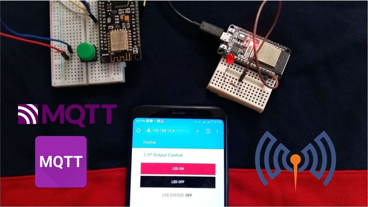
In this tutorial, we will learn to perform MQTT communication with ESP8266 NodeMCU, ESP32, and Node-Red by publishing and subscribing to MQTT topics. There will be one ESP8266 MQTT publisher connected with a push button and one ESP32 connected with an LED as a subscriber. We will publish ON/OFF messages to MQTT with ESP8266 and one ESP32 with the LED will act as a subscriber and accordingly, turn the LED ON/OFF. Node-Red Dashboard will also subscribe to the MQTT topic and display the MQTT messages on the Dashboard to indicate the status of the LED. Moreover, Node-Red will also be able to publish to the topic via ON/OFF buttons displayed on the dashboard. Hence we have two MQTT publishers: ESP8266 connected with push button and Node-Red and two MQTT subscribers: ESP32 connected with LED and Node-RED.
We will use the Mosquitto broker that is installed on the Raspberry Pi. But if you do not have Raspberry Pi, you can also install it on your Windows or Linux Ubuntu machine.
Both Publishers and Subscribers will make connections with the MQTT broker installed on Raspberry Pi. After that, the ESP8266 will publish messages to the Node-Red dashboard, and to the ESP32 subscriber on specified topic. Likewise, the Node-RED dashboard will also publish messages on the specified topic when the ON/OFF buttons are clicked.
ESP8266 NodeMCU MQTT Control Output Project Overview
The diagram below illustrates the process that we will follow in our ESP8266 MQTT Control Output Multiple Publisher and Multiple Subscriber project.
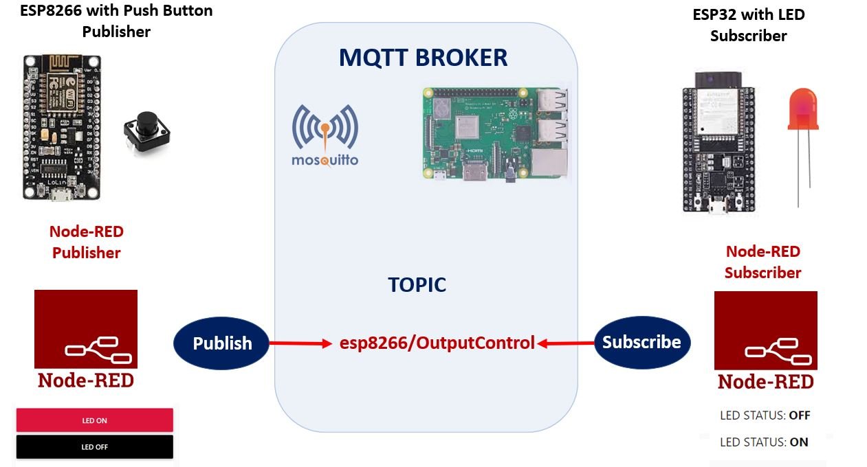
- An ESP8266 board connected with a push button will connect to the MQTT broker. We will use Mosquitto broker on Raspberry Pi. Refer to the following article (Install Mosquitto MQTT Broker on Raspberry Pi) to successfully install it in Raspberry Pi before moving forward.
- This ESP8266 board publishes “ON” message when the push button is pressed and “OFF” message when the push button is released on the MQTT topic: esp8266/OutputControl.
- Likewise, two ON and OFF buttons in Node-Red dashboard also publish similar messages to the same topic when either of the button is clicked.
- We have Node-Red and an ESP32 as subscribers to these two topics. Node-Red receives the message and displays it in its dashboard as LED Status. Whereas, the subscriber ESP32 board connected with an LED, turns it ON and OFF according to the message received.

MQTT Protocol Introduction
- MQTT is known as Message Queuing Telemetry Transport protocol.
- It is a lightweight messaging protocol and helps resource constrained network clients with a simple communication mechanism.
- Unlike, most messaging system, we don’t have to assign addresses to MQTT clients.
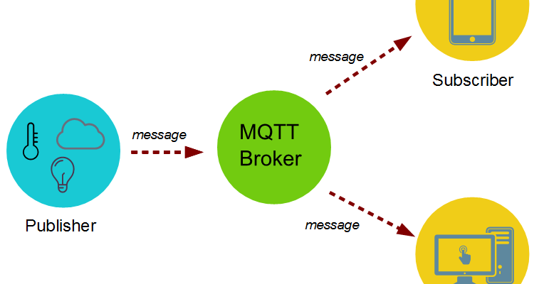
- MQTT uses simple publish/subscribe communication based on a topic.
- This protocol runs on top of TCP / IP in order to provide reliable data delivery.
For a detailed tutorial regarding MQTT, its main components, MQTT broker and working follow the link:
ESP8266 as an MQTT Publisher
Our ESP8266 MQTT Publisher is connected with a push button.
To connect ESP8266 with a push button we will require the following components.
Required Components
- ESP8266 module
- 10k ohm resistor
- Breadboard
- Connecting wires
Assemble your circuit as follows:

The push-button has four terminals. One terminal is powered by 3.3 volts from ESP8266 and the other terminal is connected by GPIO13 (D7) and the 10k ohm resistor which acts as a pull-down resistor. The other end of the resistor is connected with the common ground.
When the push button is pressed, a logic state of high (1) will be passed on GPIO13 and the push button input will be in a high state. When the button is released a logic state of low (0) will be passed on GPIO13 and the push button input will be in a logic state LOW.
Install MQTT Arduino Libraries
Before we proceed further, you should make sure that you have the latest version of Arduino IDE installed on your system. Moreover, you should also install an ESP8266 add-on in Arduino IDE. If your IDE does not have the plugin installed you can visit the link below:
Installing ESP8266 library in Arduino IDE and upload code
For this project, we will have to install libraries for MQTT.
Install Async MQTT Client Library and ESPAsyncTCP Library
We will use Async MQTT Client Library by Marvin Roger to use MQTT with ESP8266. ESPAsyncTCP is another library that we will be incorporating as it is required for our ESP8266 MQT project. Both of these libraries are not available in the Arduino library manager. Therefore, we will have to download and install them on our ESP8266 board ourselves.
- To install Async MQTT Client library, click here to download. You will download the library as a .zip folder which you will extract. Then, transfer this folder to the library folder in your Arduino IDE.
- To install the ESPAsync TCP library for free, click here to download. You will download the library as a .zip folder which you will extract and rename as ‘ESPAsyncTCP.’ Then, transfer this folder to the installation library folder in your Arduino IDE.
Similarly, you can also go to Sketch > Include Library > Add .zip Library inside the IDE to add the libraries. After installation of the libraries, restart your IDE.
ESP8266 MQTT Control Output Publisher Arduino Sketch
Open your Arduino IDE and go to File > New to open a new file. Copy the code given below in that file and save it. You need to enter your network credentials and your Raspberry Pi IP address. This sketch will develop an ESP8266 MQTT publisher by following the steps given below:
- Connecting the ESP8266 board with the local network
- Setting up the push button
- Connecting the ESP8266 to the MQTT broker
- Publishing the MQTT message to the MQTT topic
#include <ESP8266WiFi.h>
#include <Ticker.h>
#include <AsyncMqttClient.h>

//replace with your network credentials
#define WIFI_SSID "YOUR_SSID"
#define WIFI_PASSWORD "YOUR_PASSWORD"

// Raspberry Pi Mosquitto MQTT Broker
#define MQTT_HOST IPAddress(192, 168, 1, XYZ)
#define MQTT_PORT 1883

//MQTT Topic
#define MQTT_PUB_Output "esp8266/OutputControl"

const int PushButton = 15;
int Push_button_state;
bool Push_button_Prv_state = false;

AsyncMqttClient mqttClient;
Ticker mqttReconnectTimer;

WiFiEventHandler wifiConnectHandler;
WiFiEventHandler wifiDisconnectHandler;
Ticker wifiReconnectTimer;


void connectToWifi() {
  Serial.println("Connecting to Wi-Fi...");
  WiFi.begin(WIFI_SSID, WIFI_PASSWORD);
}

void onWifiConnect(const WiFiEventStationModeGotIP& event) {
  Serial.println("Connected to Wi-Fi.");
  connectToMqtt();
}

void onWifiDisconnect(const WiFiEventStationModeDisconnected& event) {
  Serial.println("Disconnected from Wi-Fi.");
  mqttReconnectTimer.detach();
  wifiReconnectTimer.once(2, connectToWifi);
}

void connectToMqtt() {
  Serial.println("Connecting to MQTT...");
  mqttClient.connect();
}

void onMqttConnect(bool sessionPresent) {
  Serial.println("Connected to MQTT.");
  Serial.print("Session present: ");
  Serial.println(sessionPresent);
}

void onMqttDisconnect(AsyncMqttClientDisconnectReason reason) {
  Serial.println("Disconnected from MQTT.");

  if (WiFi.isConnected()) {
    mqttReconnectTimer.once(2, connectToMqtt);
  }
}

void onMqttPublish(uint16_t packetId) {
  Serial.print("Publish acknowledged.");
  Serial.print("  packetId: ");
  Serial.println(packetId);
}

void setup() {
  Serial.begin(115200);
  Serial.println();
  pinMode(PushButton, INPUT);

  wifiConnectHandler = WiFi.onStationModeGotIP(onWifiConnect);
  wifiDisconnectHandler = WiFi.onStationModeDisconnected(onWifiDisconnect);

  mqttClient.onConnect(onMqttConnect);
  mqttClient.onDisconnect(onMqttDisconnect);
  mqttClient.onPublish(onMqttPublish);
  mqttClient.setServer(MQTT_HOST, MQTT_PORT);

  connectToWifi();
}

void loop() {
  Push_button_state = digitalRead(PushButton);
  if (Push_button_state == HIGH && Push_button_Prv_state == false)
  {
    // Publish an MQTT message on topic esp8266/OutputControl
    uint16_t packetIdPub1 = mqttClient.publish(MQTT_PUB_Output, 1, true, "ON");
    Serial.printf("Publishing on topic %s at QoS 1, packetId: %i", MQTT_PUB_Output, packetIdPub1);
    Serial.println(" Message: ON");
    Push_button_Prv_state = true;
  }
  else if (Push_button_state == LOW && Push_button_Prv_state == true)
  {
    // Publish an MQTT message on topic esp8266/OutputControl
    uint16_t packetIdPub2 = mqttClient.publish(MQTT_PUB_Output, 1, true, "OFF");
    Serial.printf("Publishing on topic %s at QoS 1, packetId %i: ", MQTT_PUB_Output, packetIdPub2);
    Serial.println(" Message: OFF");
    Push_button_Prv_state = false;
  }
  delay(1000);
}
How does Code Works?
We will start off by including the necessary libraries for our project. These include the libraries that we previously installed as well as ESP8266WiFi library as the ESP8266 connects with the internet and Ticker library to generate timers.
#include <ESP8266WiFi.h>
#include <Ticker.h>
#include <AsyncMqttClient.h>
Next, define your network credentials in the WIFI_SSID and WIFI_PASSWORD variables. The ESP8266 will connect to this network.
//replace with your network credentials
#define WIFI_SSID "YOUR_SSID"
#define WIFI_PASSWORD "YOUR_PASSWORD"
Define your Raspberry Pi IP address. This will be used by ESP8266 to connect to the Mosquitto Broker.
#define MQTT_HOST IPAddress(192, 168, 1, XYZ) //specify your Raspberry Pi IP AddressAlso, specify the MQTT port which is 1883 (default).
#define MQTT_PORT 1883Next we will define the topic which the ESP8266 board will publish to. The MQTT message will be published to esp8266/OutputControl.
#define MQTT_PUB_Output "esp8266/OutputControl"We will create a variable to store the GPIO pin through which the push button is connected. We have used GPIO13 in this project.
const int PushButton = 13;Next, we will define the states of the push button. The ‘Push_button_state’ variable will save the current state of the push button whereas ‘Push_button_Prv_state’ will hold the last previous state of the push button. We have also set the ‘Push_button_Prv_state’ to false.
int Push_button_state;
bool Push_button_Prv_state = false;
To manage the MQTT client, we will create an AsyncMqttClient object named ‘mqttClient.’
AsyncMqttClient mqttClient;Moreover, we will also be using Ticker timers to reconnect to the Wi-Fi and the broker in case of disconnection. Hence, we will create two objects of Ticker library, one for the MQTT (mqttReconnectTimer) and another for the Wi-Fi (wifiReconnectTimer).
Ticker mqttReconnectTimer;
Ticker wifiReconnectTimer;
MQTT Functions
Next we have a series of MQTT callback functions that come with the library.
The connectToWifi() function is responsible for connecting the ESP8266 board to our Wi-Fi network. The onWifiConnect() function is called when the ESP8266 successfully connects to the Wi-Fi. A relevant message is printed in the serial monitor and the connectToMqtt() function is called to establish connection with the MQTT broker. Similarly, the onWifiDisconnect() function is called when the ESP8266 losses the Wi-Fi connection. It tries to reconnect to Wi-Fi and stops the MQTT reconnection timer.
void connectToWifi() {
  Serial.println("Connecting to Wi-Fi...");
  WiFi.begin(WIFI_SSID, WIFI_PASSWORD);
}

void onWifiConnect(const WiFiEventStationModeGotIP& event) {
  Serial.println("Connected to Wi-Fi.");
  connectToMqtt();
}

void onWifiDisconnect(const WiFiEventStationModeDisconnected& event) {
  Serial.println("Disconnected from Wi-Fi.");
  mqttReconnectTimer.detach();
  wifiReconnectTimer.once(2, connectToWifi);
}
The connectToMqtt() function is responsible for connecting the ESP8266 board to the MQTT broker. The onMqttConnect() function is called when the ESP8266 successfully connects with the broker. On the other hand, the onMqttDisconect() function is called when the ESP8266 disconnects from the broker and if it is connected with Wi-Fi then it tries to reconnect with the MQTT broker. Relevant messages are printed in the serial monitor in each case.
void connectToMqtt() {
  Serial.println("Connecting to MQTT...");
  mqttClient.connect();
}

void onMqttConnect(bool sessionPresent) {
  Serial.println("Connected to MQTT.");
  Serial.print("Session present: ");
  Serial.println(sessionPresent);
}

void onMqttDisconnect(AsyncMqttClientDisconnectReason reason) {
  Serial.println("Disconnected from MQTT.");

  if (WiFi.isConnected()) {
    mqttReconnectTimer.once(2, connectToMqtt);
  }
}
The onMqttPublish() is responsible for printing the packet id in the serial monitor when the message is published to your topic.
void onMqttPublish(uint16_t packetId) {
  Serial.print("Publish acknowledged.");
  Serial.print("  packetId: ");
  Serial.println(packetId);
}
setup()
Inside the setup() function, we start the serial communication at a baud rate of 115200.
Serial.begin(115200);Configure the Push Button pin as an input pin by using pinMode() function.
pinMode(PushButton, INPUT);Next we will create handlers for Wi-Fi connection and disconnection.
 wifiConnectHandler = WiFi.onStationModeGotIP(onWifiConnect);
 wifiDisconnectHandler = WiFi.onStationModeDisconnected(onWifiDisconnect);
Moreover, call the rest of the callback functions that we previously described as well. These include onConnect(), onDisconnect() and onPublish(). Additionally, set the MQTT server by calling the setServer() function on the AsyncMqttClient object. Specify the MQTT_HOST and MQTT_PORT as parameters inside it. Connect ESP8266 to the Wi-Fi network by calling connectToWifi() function.
  mqttClient.onConnect(onMqttConnect);
  mqttClient.onDisconnect(onMqttDisconnect);
  mqttClient.onPublish(onMqttPublish);
  mqttClient.setServer(MQTT_HOST, MQTT_PORT);
  connectToWifi();
loop()
Inside the loop() function, the ESP8266 board first reads the push button state. The digitalRead() function reads the state of the push button and stores its value in the variable Push_button_state.
Push_button_state = digitalRead(PushButton);Then we will use an if statement to check the push button state and its previous state.
If the push button state is high and the previous state is false which indicates a push button was pressed. Then we will publish the message “ON” on the topic esp8266/OutputControl. The previous state will be set to true now.
To publish an MQTT message, we use the publish() method on the AsyncMqttClient object. It takes in four arguments. The first argument is the MQTT topic. The second argument is the quality of service (QoS). It can take values of 0, 1 or 2 and is a mechanism to monitor the deliverance of the message. The third argument is the retain flag. Lastly, the fourth argument is the payload which we want to publish.
If the push button state is low and the previous state is true which indicates a push button was released after being pressed. Then we will publish the message “OFF” on the topic esp8266/OutputControl. The previous state will be set to false now.
 if (Push_button_state == HIGH && Push_button_Prv_state == false)
  {
    // Publish an MQTT message on topic esp8266/OutputControl
    uint16_t packetIdPub1 = mqttClient.publish(MQTT_PUB_Output, 1, true, "ON");
    Serial.printf("Publishing on topic %s at QoS 1, packetId: %i", MQTT_PUB_Output, packetIdPub1);
    Serial.println(" Message: ON");
    Push_button_Prv_state = true;
  }
  else if (Push_button_state == LOW && Push_button_Prv_state == true)
  {
    // Publish an MQTT message on topic esp8266/OutputControl
    uint16_t packetIdPub2 = mqttClient.publish(MQTT_PUB_Output, 1, true, "OFF");
    Serial.printf("Publishing on topic %s at QoS 1, packetId %i: ", MQTT_PUB_Output, packetIdPub2);
    Serial.println(" Message: OFF");
    Push_button_Prv_state = false;
  }
Demonstration
Choose the correct board and COM port. Go to Tools > Board and select NodeMCU 1.0. Next, go to Tools > Port and select the appropriate port through which your board is connected.

Click on the upload button to upload the code into the ESP8266 board. After you have uploaded your code to the board press its RST button.

Open your Serial Monitor to view the progress of the project. You will be able to view if the status of the Wi-Fi and the Broker connection and the publishing.

ESP32 as an MQTT Control Output Subscriber
Let us now set up an ESP32 board connected with an LED as a subscriber to the esp8266/OutputControl topic. When this ESP32 gets connected with the MQTT Broker, it will be able to turn the LED ON and OFF according to the message received.
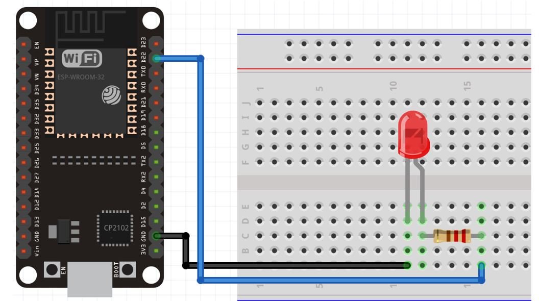
Connecting ESP32 with LED
We will need the following components.
Required Components
- ESP32 module
- One LED
- 220-ohm resistor
- Breadboard
- Connecting wires
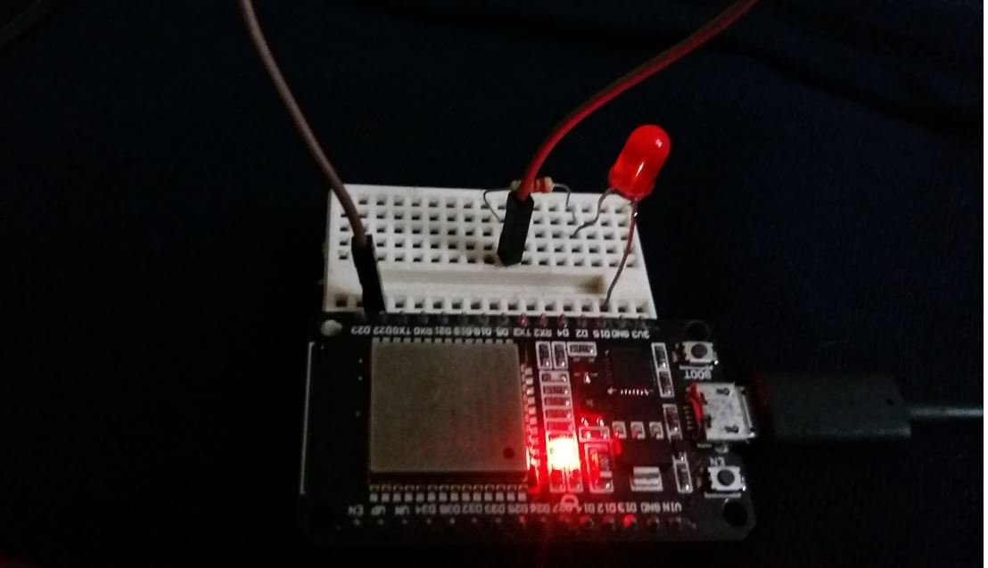
We can see that GPIO22 is connected with the anode pin of LED through a 220-ohm resistor (current limiting) and the cathode pin is connected with the common ground.
ESP32 MQTT Control Output Subscriber Arduino Sketch
Open your Arduino IDE and go to File > New to open a new file. Copy the code given below in that file and save it. You need to enter your network credentials and your Raspberry Pi IP address. This sketch will develop an ESP32 MQTT subscriber by following the steps given below:
- Connecting the ESP32 board with the local network
- Setting up the LED
- Connecting the ESP32 to the MQTT broker
- Subscribing to the MQTT topic in order to receive them
#include <WiFi.h>
extern "C" {
  #include "freertos/FreeRTOS.h"
  #include "freertos/timers.h"
}
#include <AsyncMqttClient.h>


//replace with your network credentials
#define WIFI_SSID "YOUR_SSID"
#define WIFI_PASSWORD "YOUR_PASSWORD"


#define MQTT_HOST IPAddress(192, 168, 1, XYZ)   //specify your Raspberry Pi IP Address
#define MQTT_PORT 1883

//MQTT Topics
#define MQTT_SUB_Output "esp8266/OutputControl"

const int LEDPIN = 22;

AsyncMqttClient mqttClient;
TimerHandle_t mqttReconnectTimer;
TimerHandle_t wifiReconnectTimer;

void connectToWifi() {
  Serial.println("Connecting to Wi-Fi...");
  WiFi.begin(WIFI_SSID, WIFI_PASSWORD);
}

void connectToMqtt() {
  Serial.println("Connecting to MQTT...");
  mqttClient.connect();
}

void WiFiEvent(WiFiEvent_t event) {
  Serial.printf("[WiFi-event] event: %dn", event);
  switch(event) {
    case SYSTEM_EVENT_STA_GOT_IP:
      Serial.println("WiFi connected");
      Serial.println("IP address: ");
      Serial.println(WiFi.localIP());
      connectToMqtt();
      break;
    case SYSTEM_EVENT_STA_DISCONNECTED:
      Serial.println("WiFi lost connection");
      xTimerStop(mqttReconnectTimer, 0); // ensure we don't reconnect to MQTT while reconnecting to Wi-Fi
      xTimerStart(wifiReconnectTimer, 0);
      break;
  }
}

void onMqttConnect(bool sessionPresent) {
  Serial.println("Connected to MQTT.");
  Serial.print("Session present: ");
  Serial.println(sessionPresent);

  uint16_t packetIdSub = mqttClient.subscribe(MQTT_SUB_Output, 2);
  Serial.print("Subscribing at QoS 2, packetId: ");
  Serial.println(packetIdSub);
}


void onMqttDisconnect(AsyncMqttClientDisconnectReason reason) {
  Serial.println("Disconnected from MQTT.");
  if (WiFi.isConnected()) {
    xTimerStart(mqttReconnectTimer, 0);
  }
}

void onMqttSubscribe(uint16_t packetId, uint8_t qos) {
  Serial.println("Subscribe acknowledged.");
  Serial.print("  packetId: ");
  Serial.println(packetId);
  Serial.print("  qos: ");
  Serial.println(qos);
}
void onMqttUnsubscribe(uint16_t packetId) {
  Serial.println("Unsubscribe acknowledged.");
  Serial.print("  packetId: ");
  Serial.println(packetId);
}


void onMqttMessage(char* topic, char* payload, AsyncMqttClientMessageProperties properties, size_t len, size_t index, size_t total) {
  Serial.println("\n Publish received.");
  Serial.print("topic: ");
  Serial.println(topic);
  String messageTemp;
  for (int i = 0; i < len; i++) {
    messageTemp += (char)payload[i];
  }
    Serial.print("Message: ");
    Serial.println(messageTemp);

  if (messageTemp == "ON"){
  digitalWrite(LEDPIN, HIGH);
  Serial.println("LED is now ON!");
  }

  else{
  digitalWrite(LEDPIN, LOW);
  Serial.println("LED is now OFF");
  }
}
void setup() {
  Serial.begin(115200);
  pinMode(LEDPIN, OUTPUT);

  mqttReconnectTimer = xTimerCreate("mqttTimer", pdMS_TO_TICKS(2000), pdFALSE, (void*)0, reinterpret_cast<TimerCallbackFunction_t>(connectToMqtt));
  wifiReconnectTimer = xTimerCreate("wifiTimer", pdMS_TO_TICKS(2000), pdFALSE, (void*)0, reinterpret_cast<TimerCallbackFunction_t>(connectToWifi));

  WiFi.onEvent(WiFiEvent);

  mqttClient.onConnect(onMqttConnect);
  mqttClient.onDisconnect(onMqttDisconnect);
  mqttClient.onSubscribe(onMqttSubscribe);
  mqttClient.onUnsubscribe(onMqttUnsubscribe);
  mqttClient.onMessage(onMqttMessage);
  mqttClient.setServer(MQTT_HOST, MQTT_PORT);
  connectToWifi();
}

void loop() {}
How does Code Works?
Most of the code is similar to the previous code which was used to publish to topics via MQTT. In this one, we will be subscribing to those topics and control the LED according to the message received.
We will start off by including the necessary libraries. This includes all the libraries that we included previously to set up the ESP32 MQTT Client.
#include <WiFi.h>
extern "C" {
  #include "freertos/FreeRTOS.h"
  #include "freertos/timers.h"
}
#include <AsyncMqttClient.h>
Next, define your network credentials in the WIFI_SSID and WIFI_PASSWORD variables. The ESP32 will connect to this network.
//replace with your network credentials
#define WIFI_SSID "YOUR_SSID"
#define WIFI_PASSWORD "YOUR_PASSWORD"
Define your Raspberry Pi IP address. This will be used by ESP32 to connect to the Mosquitto Broker.
#define MQTT_HOST IPAddress(192, 168, 1, XYZ) //specify your Raspberry Pi IP AddressAlso, specify the MQTT port which is 1883 (default).
#define MQTT_PORT 1883Next, we will define the topic which the ESP32 board will subscribe to. The ON/OFF message is published to esp8266/OutputControl. Hence, the ESP32 subscribes to this topic in order to acquire it.
#define MQTT_SUB_Output "esp8266/OutputControl"Then, we will define the variable ‘LEDPIN’ to save the GPIO pin through which the LED is connected i.e. GPIO22.
const int LEDPIN = 22; To manage the MQTT client, we will create an AsyncMqttClient object named ‘mqttClient.’
AsyncMqttClient mqttClient;Moreover, we will also be using FreeRTOS timers to reconnect to the Wi-Fi and the broker in case of disconnection. Hence, we will create two task handles, one for the MQTT and another for the Wi-Fi.
TimerHandle_t mqttReconnectTimer;
TimerHandle_t wifiReconnectTimer;
MQTT Functions
Next we have a series of MQTT callback functions that come with the library.
The connectToWifi() function is responsible for connecting the ESP32 board to our Wi-Fi network. The connectToMqtt() function is responsible for connecting the ESP32 board to the MQTT broker. The WiFiEvent() function is responsible for operating the Wi-Fi events. This includes printing the ESP32 IP address when it connects with the Wi-Fi and incase of disconnection, it starts the the Wi-Fi reconnection timer and stops the MQTT reconnection timer.
void connectToWifi() {
  Serial.println("Connecting to Wi-Fi...");
  WiFi.begin(WIFI_SSID, WIFI_PASSWORD);
}

void connectToMqtt() {
  Serial.println("Connecting to MQTT...");
  mqttClient.connect();
}

void WiFiEvent(WiFiEvent_t event) {
  Serial.printf("[WiFi-event] event: %dn", event);
  switch(event) {
    case SYSTEM_EVENT_STA_GOT_IP:
      Serial.println("WiFi connected");
      Serial.println("IP address: ");
      Serial.println(WiFi.localIP());
      connectToMqtt();
      break;
    case SYSTEM_EVENT_STA_DISCONNECTED:
      Serial.println("WiFi lost connection");
      xTimerStop(mqttReconnectTimer, 0);
      xTimerStart(wifiReconnectTimer, 0);
      break;
  }
}
Subscribing to Topics
The onMqttConnect() function is called when the ESP32 successfully connects with the broker. Then it subscribes to the topic using the subscribe() method on the AsyncMqttClient object. It takes in two parameters. The first parameter is the topic which is to be subscribed to and the second parameter is the QoS. This returns the packet id which is displayed in the serial monitor.
On the other hand, the onMqttDisconect() function is called when the ESP32 disconnects from the broker. If it is connected with Wi-Fi then it starts the MQTT reconnection timer. Relevant messages are printed in the serial monitor in each case.
void onMqttConnect(bool sessionPresent) {
  Serial.println("Connected to MQTT.");
  Serial.print("Session present: ");
  Serial.println(sessionPresent);

  uint16_t packetIdSub = mqttClient.subscribe(MQTT_SUB_Output, 2);
  Serial.print("Subscribing at QoS 2, packetId: ");
  Serial.println(packetIdSub);
}

void onMqttDisconnect(AsyncMqttClientDisconnectReason reason) {
  Serial.println("Disconnected from MQTT.");
  if (WiFi.isConnected()) {
    xTimerStart(mqttReconnectTimer, 0);
  }
}
The onMqttSubscribe() prints the packet id and the QoS in the serial monitor, along with ‘Subscribe acknowledged.’ The onMqttUnsubscribe() prints the packet id along with ‘Unsubscribe acknowledged.’ These functions are called in the case of a successful subscription or un-subscription of a topic respectively.
void onMqttSubscribe(uint16_t packetId, uint8_t qos) {
  Serial.println("Subscribe acknowledged.");
  Serial.print("  packetId: ");
  Serial.println(packetId);
  Serial.print("  qos: ");
  Serial.println(qos);
}
void onMqttUnsubscribe(uint16_t packetId) {
  Serial.println("Unsubscribe acknowledged.");
  Serial.print("  packetId: ");
  Serial.println(packetId);
}
The onMqttMessage() is responsible for obtaining the MQTT message from the subscribed topic and controlling the LED. The string variable ‘messageTemp’ holds the MQTT message. If the received message is “ON” then turn the LED on by using digitalWrite(). If the received message is “OFF” then turn the LED off.
void onMqttMessage(char* topic, char* payload, AsyncMqttClientMessageProperties properties, size_t len, size_t index, size_t total) {
  Serial.println("\n Publish received.");
  Serial.print("topic: ");
  Serial.println(topic);
  String messageTemp;
  for (int i = 0; i < len; i++) {
    messageTemp += (char)payload[i];
  }
    Serial.print("Message: ");
    Serial.println(messageTemp);

  if (messageTemp == "ON"){
  digitalWrite(LEDPIN, HIGH);
  Serial.println("LED is now ON!");
  }

  else{
  digitalWrite(LEDPIN, LOW);
  Serial.println("LED is now OFF");
  }
}
setup()
Inside the setup() function, we will open a serial connection at a baud rate of 115200. Moreover, configure the LEDPIN as an output pin by using the pinMode() function.
Serial.begin(115200);
pinMode(LEDPIN, OUTPUT);
Next we create the timers for the MQTT and Wi-Fi reconnection.
 mqttReconnectTimer = xTimerCreate("mqttTimer", pdMS_TO_TICKS(2000), pdFALSE, (void*)0, reinterpret_cast<TimerCallbackFunction_t>(connectToMqtt));
  wifiReconnectTimer = xTimerCreate("wifiTimer", pdMS_TO_TICKS(2000), pdFALSE, (void*)0, reinterpret_cast<TimerCallbackFunction_t>(connectToWifi));
Call the WiFiEvent() function, to display the Wi-Fi status in the serial monitor.
WiFi.onEvent(WiFiEvent);Moreover, call the rest of the callback functions that we previously described as well. These include onConnect(), onDisconnect(), onSubscribe(), onUnSubscribe() and onMessage(). Additionally, set the MQTT server by calling the setServer() function on the AsyncMqttClient object. Specify the MQTT_HOST and MQTT_PORT as parameters inside it. Connect ESP32 to the Wi-Fi network by calling connectToWifi() function.
  mqttClient.onConnect(onMqttConnect);
  mqttClient.onDisconnect(onMqttDisconnect);
  mqttClient.onSubscribe(onMqttSubscribe);
  mqttClient.onUnsubscribe(onMqttUnsubscribe);
  mqttClient.onMessage(onMqttMessage);
  mqttClient.setServer(MQTT_HOST, MQTT_PORT);

  connectToWifi();
Demonstration
To see the demonstration of the above code, upload the code to ESP32 connected with the LED. Before uploading the code, make sure to select the ESP32 Dev Module from Tools > Board.

Also, select the correct COM port to which this ESP32 board is connected from Tools > Port.
Once the code is uploaded to ESP32, press the push button and the LED will turn ON. Now release the push button and the LED will turn OFF.
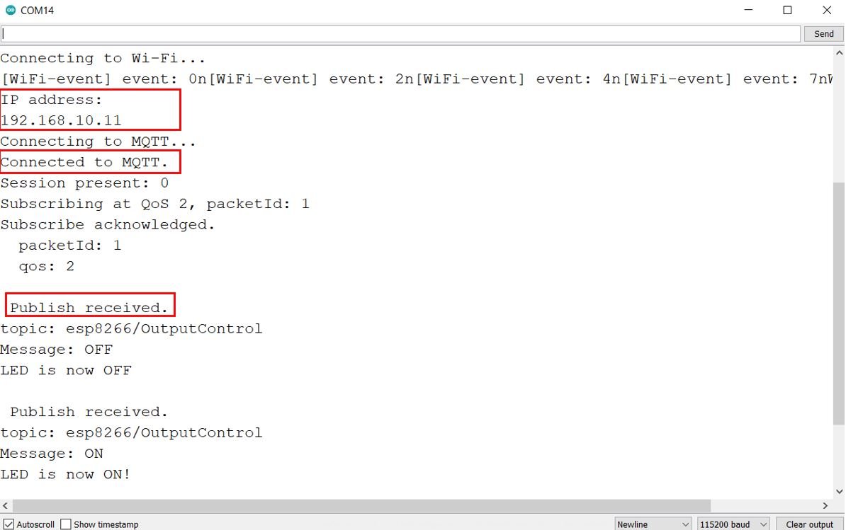
Open the serial monitor and you will be able to see the following messages indicating a successful connection to Wi-Fi, MQTT Broker, and subscription.
Setting up Node-Red Dashboard as an MQTT Control Output Subscriber and Publisher
Now let us build the Node-Red Dashboard to publish the MQTT messages to the topic and also subscribe to it.
We will be using Node-Red to publish and subscribe to the topics. However, you can use any other MQTT subscription service as well. In order to get started with Node-Red on Raspberry Pi, refer to the guide:
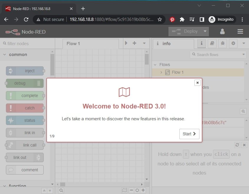
To access Node-RED, we need the IP address of our Raspberry Pi and the port number on which Node-RED is accessible. By default, it starts on port 1880. Open any web browser and enter the RPI IP address followed by the port number.
192.168.18.8:1880Creating Flow
This will open the Node-RED interface. You can start creating the flow.
Make sure the dashboard is already installed. Head over to the extreme right side and find dashboard.
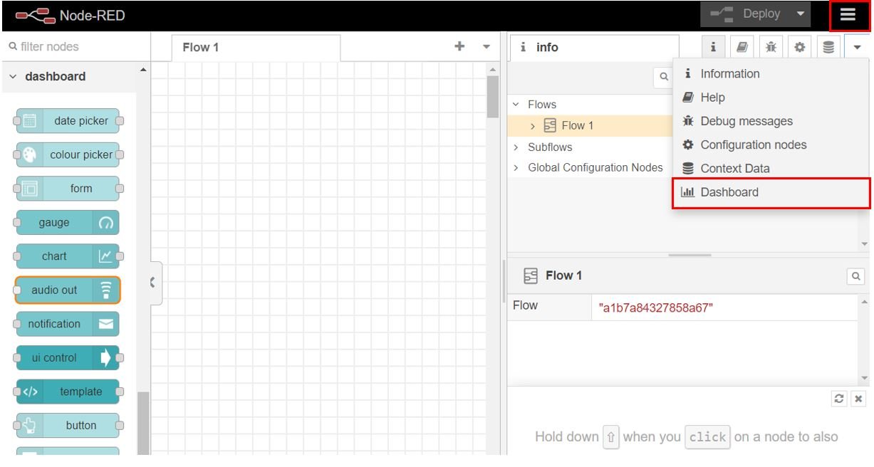
After you click it, the Dashboard tab appears. The first step is to create the tab. Head over to the Dashboard tab and click +tab to create a new tab. Specify the name and icon and click Update for the changes to take place. Here we are using icons from Angular Material Icons.
We will create one tab named Home.
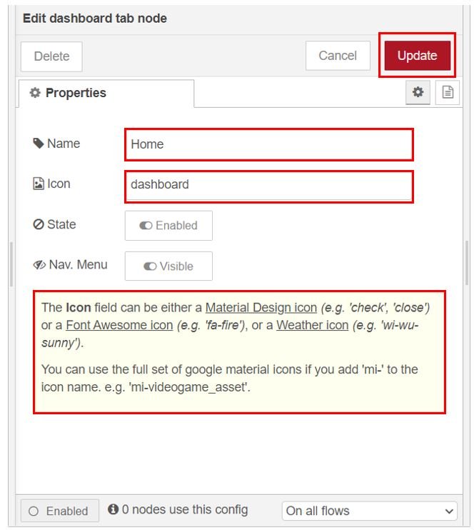
Note: You can use any name according to your preference but for the icon you have to use one available at these three links found below:
Add Widgets
The next step is to add the widgets. We will add one group to the tab. Click +group in the tab and create the group. We have named it ‘ESP Output Control.’

Add one mqtt in node and one text node to display the MQTT message. Add two buttons and one mqtt out node for publishing to the MQTT topic. Head over to the Nodes section found at the far left and scroll down to view the nodes under Dashboard. Drag and drop one text node, two button nodes, one mqtt in and one mqtt out node to the flow as shown below:

Publishing to MQTT Topic
Now double click the first button node to edit its properties as shown below. This button will publish the message “ON” to the topic when it will be clicked.

Now double click the second button node to edit its properties as shown below. This button will publish the message “OFF” to the topic when it will be clicked.

Edit the mqtt out properties as shown below. Here we have set the server (MQTT Broker) to localhost:1883 as we are using Mosquitto Broker on our Raspberry Pi. Specify the topic where we want to publish. Click the Done button.

Subscribing to MQTT Topic
Next we will add the topic subscription. Edit the properties of the text node as shown below:

Edit the properties of the mqtt in node as shown below. Here we have set the sever (MQTT Broker) to localhost:1883 as we are using Mosquitto Broker on our Raspberry Pi. Specify the topic to be subscribed. This node is being subscribed to the topic ‘esp8266/OutputControl.’ Click the Done button.

Finally wire the nodes as shown below. Now deploy the changes by clicking the Deploy button found at the top.

To view the UI, open a new web browser and type: http://Your_RPI_IP_address:1880/ui
The user interface will open up once you press enter.
Here you can view the dashboard consisting of the two buttons and the LED status.

Testing
Now press the LED ON button and the LED connected with the ESP32 subscriber board will turn ON. Then press the LED OFF button and the LED will turn OFF. Additionally, the LED status will show ON or OFF according to the message received by Node-Red Dashboard. The LED status will update whenever you press/release the push button and whenever you click the LED ON and LED OFF buttons present on the Dashboard. This way we were able to set up multiple MQTT publishers and multiple MQTT subscribers.

Watch the video below:
You may also like to read:
- ESP32 MicroPython MQTT Publish Subscribe – Control Outputs
- ESP32 MQTT Publish Subscribe with Arduino IDE – Control Outputs
- ESP32 MQTT Publish Subscribe DS18B20 Readings with Arduino IDE
- ESP32 MQTT Publish Subscribe BME280 Readings with Arduino IDE
- ESP32 MQTT Publish Subscribe DHT22 Readings with Arduino IDE