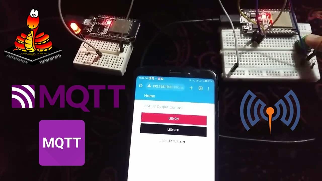
In this ESP32 MicroPython tutorial, we will learn to use MQTT with ESP32 to publish and subscribe to MQTT topics using MicroPython. We will see how to use ESP32 as an MQTT publisher and subscriber with MicroPython scripts. For demonstration, we will control ESP32 outputs by publishing MQTT messages. There will be one ESP32 MQTT publisher connected with a push button and one ESP32 connected with an LED as a subscriber. We will also publish ON/OFF messages to MQTT with ESP32 and one ESP32 with the LED will act as a subscriber and accordingly, turn the LED ON/OFF.
Recommended Components
The following components are used in this project or are helpful for getting started with MicroPython on ESP32 and ESP8266.
| Component | How it’s used in this project | Buy on Amazon |
|---|---|---|
| ESP32 Development Board (DevKit V1) | The ESP32 board flashed with MicroPython firmware. | Check Price |
| Micro USB Cable | Programs and powers the board from your PC. | Check Price |
| 5mm LED | Output LED toggled by MQTT publish/subscribe messages. | Check Price |
| Resistor Kit (220Ω) | 220Ω current-limiting resistor for the LED. | Check Price |
| Breadboard | Holds the LED, push button, and wiring. | Check Price |
| Jumper Wires | Connects the components to the ESP32. | Check Price |
As an Amazon Associate we earn from qualifying purchases. Prices and availability are accurate as of the date/time indicated and are subject to change.
Additionally, Node-Red Dashboard will also subscribe to that MQTT topic and display the LED status on the Dashboard. Moreover, Node-Red will also publish to the MQTT topic via ON/OFF buttons displayed on the dashboard to control the LED connected with the ESP32 subscriber. Consequently, we have two MQTT publishers: ESP32 connected with push button and Node-Red, and two MQTT subscribers: ESP32 connected with LED and Node-RED.
We will use the Mosquitto broker that is installed on the Raspberry Pi. But if you do not have Raspberry Pi, you can also install it on your Windows or Linux Ubuntu machine.
Both Publisher and Subscriber ESP32 and Node-RED will make connections with the MQTT broker installed on Raspberry Pi. After that, one ESP32 will publish messages to the Node-Red dashboard, and to the ESP32 subscriber on a specified topic. Likewise, the Node-RED dashboard will also publish messages on the specified topic when the ON/OFF buttons are clicked.
Prerequisites
Before continuing with this project, make sure you have the latest version of MicroPython and Thonny IDE installed on your PC. Your ESP32 board should be already flashed with the firmware. Additionally, we will be using the Mosquitto broker to send and receive messages. So make sure your broker is installed on the Raspberry Pi.
- Getting Started with uPyCraft IDE on ESP32 and ESP8266
- Getting Started with Thonny MicroPython IDE for ESP32 and ESP8266
If you want to use VS Code, you can follow this guide:
- MicroPython ESP32 and ESP8266: Program with VS Code and Pymakr
- Flash MicroPython Firmware with esptool.py to ESP32 and ESP8266
ESP32 MicroPython MQTT Control Output Project Overview
The diagram below illustrates the process that we will follow in our ESP32 MQTT Control Output Multiple Publisher and Multiple Subscriber project.
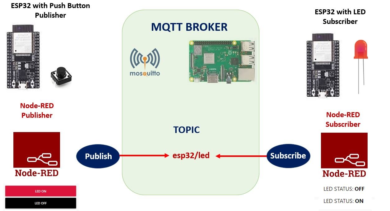
- An ESP32 board connected with a push button will connect to the MQTT broker. We will use Mosquitto broker on Raspberry Pi. Refer to the following article (Install Mosquitto MQTT Broker on Raspberry Pi) to successfully install it in Raspberry Pi before moving forward.
- This ESP32 board publishes “ON” message when the push button is pressed and “OFF” message when the push button is released on the MQTT topic: esp32/led.
- Likewise, two ON and OFF buttons in Node-Red dashboard also publish similar messages to the same topic when either of the button is clicked.
- We have Node-Red and another ESP32 as subscribers to these two topics. Node-Red receives the message and displays it in its dashboard as LED Status. Whereas, the subscriber ESP32 board connected with an LED, turns it ON and OFF according to the message received.
What is MQTT?
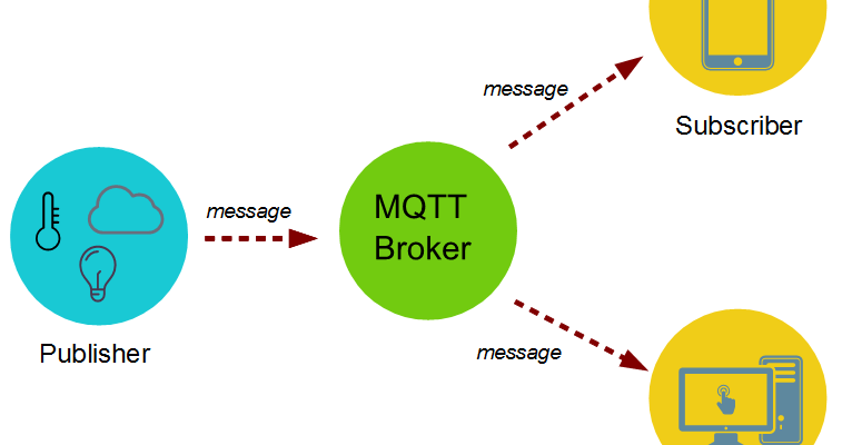
Message Queuing Telemetry Transport (MQTT) transmits messages between two devices. It follows a publish-subscribe network protocol to perform its functionality.
There are many MQTT brokers available which we can use. The main job of the broker is to receive, filter and publish messages to the clients who are subscribed. Among free self hosted brokers, Mosquitto is the most abundantly used. It is a free open source MQTT broker which works on Windows and Linux.
For a detailed tutorial regarding MQTT, its main components, MQTT broker and working follow the link:
ESP32 as an MQTT Publisher MicroPython
Our ESP32 MQTT Publisher is connected with a push button.
To connect ESP32 with a push button we will require the following components.
Required Components
- ESP32 module
- 10k ohm resistor
- Breadboard
- Connecting wires
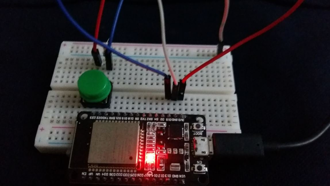
Assemble your circuit as follows:

The push-button has four terminals. One terminal is powered by 3.3 volts from ESP32 and the other terminal is connected by GPIO15 and the 10k ohm resistor which acts as a pull-down resistor. The other end of the resistor is connected with the common ground.
When the push button is pressed, a logic state of high (1) will be passed on GPIO15 and the push button input will be in a high state. When the button is released a logic state of low (0) will be passed on GPIO15 and the push button input will be in a logic state LOW.
Recommended reading: Push button with ESP32 – GPIO pins as digital input
Setting up MQTT with MicroPython
The first step is to install the umqttsimple library in MicroPython because we have to use the MQTT with our ESP32 boards.
try:
    import usocket as socket
except:
    import socket
import ustruct as struct
from ubinascii import hexlify

class MQTTException(Exception):
    pass

class MQTTClient:

    def __init__(self, client_id, server, port=0, user=None, password=None, keepalive=0,
                 ssl=False, ssl_params={}):
        if port == 0:
            port = 8883 if ssl else 1883
        self.client_id = client_id
        self.sock = None
        self.server = server
        self.port = port
        self.ssl = ssl
        self.ssl_params = ssl_params
        self.pid = 0
        self.cb = None
        self.user = user
        self.pswd = password
        self.keepalive = keepalive
        self.lw_topic = None
        self.lw_msg = None
        self.lw_qos = 0
        self.lw_retain = False

    def _send_str(self, s):
        self.sock.write(struct.pack("!H", len(s)))
        self.sock.write(s)

    def _recv_len(self):
        n = 0
        sh = 0
        while 1:
            b = self.sock.read(1)[0]
            n |= (b & 0x7f) << sh
            if not b & 0x80:
                return n
            sh += 7

    def set_callback(self, f):
        self.cb = f

    def set_last_will(self, topic, msg, retain=False, qos=0):
        assert 0 <= qos <= 2
        assert topic
        self.lw_topic = topic
        self.lw_msg = msg
        self.lw_qos = qos
        self.lw_retain = retain

    def connect(self, clean_session=True):
        self.sock = socket.socket()
        addr = socket.getaddrinfo(self.server, self.port)[0][-1]
        self.sock.connect(addr)
        if self.ssl:
            import ussl
            self.sock = ussl.wrap_socket(self.sock, **self.ssl_params)
        premsg = bytearray(b"\x10\0\0\0\0\0")
        msg = bytearray(b"\x04MQTT\x04\x02\0\0")

        sz = 10 + 2 + len(self.client_id)
        msg[6] = clean_session << 1
        if self.user is not None:
            sz += 2 + len(self.user) + 2 + len(self.pswd)
            msg[6] |= 0xC0
        if self.keepalive:
            assert self.keepalive < 65536
            msg[7] |= self.keepalive >> 8
            msg[8] |= self.keepalive & 0x00FF
        if self.lw_topic:
            sz += 2 + len(self.lw_topic) + 2 + len(self.lw_msg)
            msg[6] |= 0x4 | (self.lw_qos & 0x1) << 3 | (self.lw_qos & 0x2) << 3
            msg[6] |= self.lw_retain << 5

        i = 1
        while sz > 0x7f:
            premsg[i] = (sz & 0x7f) | 0x80
            sz >>= 7
            i += 1
        premsg[i] = sz

        self.sock.write(premsg, i + 2)
        self.sock.write(msg)
        #print(hex(len(msg)), hexlify(msg, ":"))
        self._send_str(self.client_id)
        if self.lw_topic:
            self._send_str(self.lw_topic)
            self._send_str(self.lw_msg)
        if self.user is not None:
            self._send_str(self.user)
            self._send_str(self.pswd)
        resp = self.sock.read(4)
        assert resp[0] == 0x20 and resp[1] == 0x02
        if resp[3] != 0:
            raise MQTTException(resp[3])
        return resp[2] & 1

    def disconnect(self):
        self.sock.write(b"\xe0\0")
        self.sock.close()

    def ping(self):
        self.sock.write(b"\xc0\0")

    def publish(self, topic, msg, retain=False, qos=0):
        pkt = bytearray(b"\x30\0\0\0")
        pkt[0] |= qos << 1 | retain
        sz = 2 + len(topic) + len(msg)
        if qos > 0:
            sz += 2
        assert sz < 2097152
        i = 1
        while sz > 0x7f:
            pkt[i] = (sz & 0x7f) | 0x80
            sz >>= 7
            i += 1
        pkt[i] = sz
        #print(hex(len(pkt)), hexlify(pkt, ":"))
        self.sock.write(pkt, i + 1)
        self._send_str(topic)
        if qos > 0:
            self.pid += 1
            pid = self.pid
            struct.pack_into("!H", pkt, 0, pid)
            self.sock.write(pkt, 2)
        self.sock.write(msg)
        if qos == 1:
            while 1:
                op = self.wait_msg()
                if op == 0x40:
                    sz = self.sock.read(1)
                    assert sz == b"\x02"
                    rcv_pid = self.sock.read(2)
                    rcv_pid = rcv_pid[0] << 8 | rcv_pid[1]
                    if pid == rcv_pid:
                        return
        elif qos == 2:
            assert 0

    def subscribe(self, topic, qos=0):
        assert self.cb is not None, "Subscribe callback is not set"
        pkt = bytearray(b"\x82\0\0\0")
        self.pid += 1
        struct.pack_into("!BH", pkt, 1, 2 + 2 + len(topic) + 1, self.pid)
        #print(hex(len(pkt)), hexlify(pkt, ":"))
        self.sock.write(pkt)
        self._send_str(topic)
        self.sock.write(qos.to_bytes(1, "little"))
        while 1:
            op = self.wait_msg()
            if op == 0x90:
                resp = self.sock.read(4)
                #print(resp)
                assert resp[1] == pkt[2] and resp[2] == pkt[3]
                if resp[3] == 0x80:
                    raise MQTTException(resp[3])
                return

    # Wait for a single incoming MQTT message and process it.
    # Subscribed messages are delivered to a callback previously
    # set by .set_callback() method. Other (internal) MQTT
    # messages processed internally.
    def wait_msg(self):
        res = self.sock.read(1)
        self.sock.setblocking(True)
        if res is None:
            return None
        if res == b"":
            raise OSError(-1)
        if res == b"\xd0":  # PINGRESP
            sz = self.sock.read(1)[0]
            assert sz == 0
            return None
        op = res[0]
        if op & 0xf0 != 0x30:
            return op
        sz = self._recv_len()
        topic_len = self.sock.read(2)
        topic_len = (topic_len[0] << 8) | topic_len[1]
        topic = self.sock.read(topic_len)
        sz -= topic_len + 2
        if op & 6:
            pid = self.sock.read(2)
            pid = pid[0] << 8 | pid[1]
            sz -= 2
        msg = self.sock.read(sz)
        self.cb(topic, msg)
        if op & 6 == 2:
            pkt = bytearray(b"\x40\x02\0\0")
            struct.pack_into("!H", pkt, 2, pid)
            self.sock.write(pkt)
        elif op & 6 == 4:
            assert 0

    # Checks whether a pending message from server is available.
    # If not, returns immediately with None. Otherwise, does
    # the same processing as wait_msg.
    def check_msg(self):
        self.sock.setblocking(False)
        return self.wait_msg()
Open Thonny IDE and create a new file. Copy the code given here save it your MicroPython device.

Save the new file by the name umqttsimple.py. Save this library to both ESP32 publisher and ESP32 subscriber.
ESP32 MQTT Control Output Publisher MicroPython Script
After installing the umqttsimple library, click File > Open and open the boot.py file from the MicroPython device. If the file is not present, then create one by going to File > New to open a new file. Copy the code given below in that file and save it as boot.py in your MicroPython device. You need to enter your network credentials and your Raspberry Pi IP address.
boot.py
from machine import Pin
import time
from umqttsimple import MQTTClient
import ubinascii
import machine
import micropython
import network
import esp
esp.osdebug(None)
import gc
gc.collect()

ssid = 'YOUR_SSID'
password = 'YOUR_PASSWORD'
mqtt_server = '192.168.10.8'  #Replace with your MQTT Broker IP

client_id = ubinascii.hexlify(machine.unique_id())
topic_pub = b'esp32/led'

station = network.WLAN(network.STA_IF)
station.active(True)
station.connect(ssid, password)

while station.isconnected() == False:
  pass

print('Connection successful')
print(station.ifconfig())
How the Code Works?
We start off by importing all the necessary libraries which would be required including time ,umqttsimple, MQTTClient, ubinascii, machine micropython, network, esp and Pin class from machine module.
from machine import Pin
import time
from umqttsimple import MQTTClient
import ubinascii
import machine
import micropython
import network
import esp
Then we activate the garbage collector and set the debug to ‘None.’
esp.osdebug(None)
import gc
gc.collect()
Next, we will enter our network Wi-fi, its password and the IP of our MQTT broker. You will have to specify your own figures in order for the network to connect with the MQTT and ESP32 board.
ssid = 'YOUR_SSID' #write your own wi-fi name
password = 'YOUR_PASSWORD' #write your own password
mqtt_server = '192.168.10.8'  #Replace with your MQTT Broker IP
We will create a variable push_button to configure the GPIO connected with the push button as an input pin. We have used GPIO15 in this project.
The ‘Push_button_Prv_state’ will hold the last previous state of the push button. We have set the ‘Push_button_Prv_state’ to False.
push_button = Pin(15, Pin.IN)
push_button_Prv_state = False
Then we will create a client_id variable which saves the ESP unique ID. This is required to form a MQTT client.
client_id = ubinascii.hexlify(machine.unique_id())Now will create a variable named: ‘topic_pub’. The is the topic which the ESP32 board will publish to. The MQTT message will be published to esp32/led.
topic_pub = b'esp32/led'
Next,we will connect the ESP32 board to the Wi-Fi network.
station = network.WLAN(network.STA_IF)
station.active(True)
station.connect(ssid, password)

while station.isconnected() == False:
  pass

print('Connection successful')
print(station.ifconfig())
main.py
The next step is to create the main.py file for the ESP32 Publisher. Create a new file and name it as main.py. Save it to the MicroPython device. Copy the code given below in that file.
def connect():
  print('Connecting to MQTT Broker...')
  global client_id, mqtt_server
  client = MQTTClient(client_id, mqtt_server)
  client.connect()
  print('Connected to %s MQTT broker' % (mqtt_server))
  return client

def restart_and_reconnect():
  print('Failed to connect to MQTT broker. Reconnecting...')
  time.sleep(10)
  machine.reset()

try:
  client = connect()
except OSError as e:
  restart_and_reconnect()

push_button = Pin(15, Pin.IN)
push_button_Prv_state = False

while True:
  try:
    client.check_msg()
    logic_state = push_button.value()
    #print(logic_state)
    if logic_state == 1 and push_button_Prv_state == False:
          msg = "ON"
          client.publish(topic_pub, msg)
          print('Publishing message: %s on topic %s' % (msg, topic_pub))
          push_button_Prv_state = True
    elif logic_state == 0 and push_button_Prv_state == True:
          msg ="OFF"
          client.publish(topic_pub, msg)
          print('Publishing message: %s on topic %s' % (msg, topic_pub))
          push_button_Prv_state = False
    time.sleep(1)
  except OSError as e:
    restart_and_reconnect()
How the Code Works?
First, we will define the connect() function. This is used to connect the ESP32 board with the MQTT broker. We will initialize global variables for client_id and mqtt_server. This way we will be able to use them anywhere in the program code.
The next step is to initialize the MQTTClient() method with two parameters. The first parameter is the ID of the client named as: ‘client_id’ and the second parameter is the mqtt_server which is the IP address of the broker which was already configured in the boot.py file. This method will be assigned to the object ‘client.’ Then we will connecting the client with the broker. This would be done by using the connect() method on the object which we created previously: ‘client.’
def connect():
  print('Connecting to MQTT Broker...')
  global client_id, mqtt_server
  client = MQTTClient(client_id, mqtt_server)
  client.connect()
  print('Connected to %s MQTT broker' % (mqtt_server))
  return client
In case of failure of connecting with the ESP32 board, we will also create a restart_and_reconnect() function which would display a failure message on the screen. The ESP32 development board will restart after 10 seconds.
The next step is to learn how to connect our ESP32 board to the MQTT broker. This is accomplished by forming a client. We will create a client through the connect() function which we defined previously. Moreover, we have to keep track of a failure in connection as well. In case it happens, the ESP32 board will restart.
def restart_and_reconnect():
  print('Failed to connect to MQTT broker. Reconnecting...')
  time.sleep(10)
  machine.reset()

try:
  client = connect()
except OSError as e:
  restart_and_reconnect()
Publish MQTT Message to Topic
After that, we will set up a while loop which continues endlessly by publishing the messages. The ESP32 board first reads the push button state. The push_button.value() reads the state of the push button and stores its value in the variable logic_state.
Then we will use if elif statements to check the push button logic state and its previous state.
If the push button logic state is high and the previous state is False which indicates a push button was pressed. Then we will publish the message “ON” on the topic esp32/led. The previous state will be set to True now.
If the push button state is low and the previous state is True which indicates a push button was released after being pressed. Then we will publish the message “OFF” on the topic esp32/led. The previous state will be set to False now.
To publish the messages we use the publish() method. This method has two arguments. The first argument is the topic_pub which is the publishing topic which we already configured in our boot.py file. The second argument is the msg which displays the content of the message.
In case of a failure during the process, we will call the restart_and _reconnect() function which restarts the ESP32 board.
while True:
  try:
    client.check_msg()
    logic_state = push_button.value()
    #print(logic_state)
    if logic_state == 1 and push_button_Prv_state == False:
          msg = "ON"
          client.publish(topic_pub, msg)
          print('Publishing message: %s on topic %s' % (msg, topic_pub))
          push_button_Prv_state = True
    elif logic_state == 0 and push_button_Prv_state == True:
          msg ="OFF"
          client.publish(topic_pub, msg)
          print('Publishing message: %s on topic %s' % (msg, topic_pub))
          push_button_Prv_state = False
    time.sleep(1)
  except OSError as e:
    restart_and_reconnect()
Uploading MicroPython Script
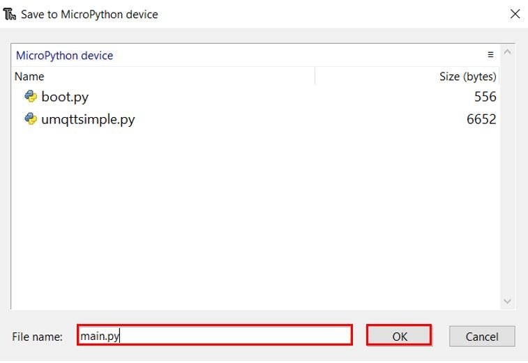
To upload this MicroPython script to your ESP32 publisher device, go to Files and click on ‘Save as’ or click the Save icon. Save the file to the MicroPython device as main.py and click ok.
Now press the Run current script icon.
This would upload the code onto our ESP32 board. After the code is uploaded, press the Enable button on your ESP32.

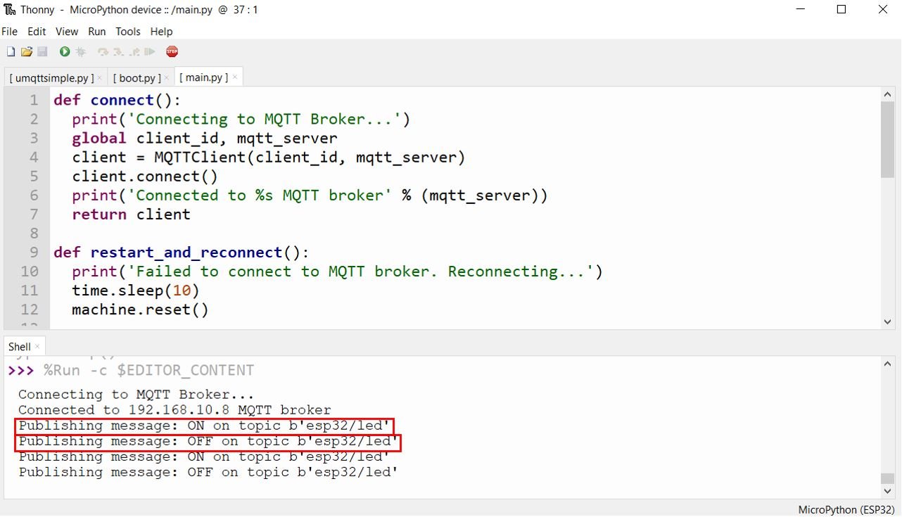
Open the Thonny Shell. The ESP32 board will first connect to the Wi-Fi and the MQTT broker. Now press the push button and you can view “ON” message being published to the esp32/led topic. When you release the push button, the message “OFF” gets published to the esp32/led topic.
ESP32 as an MQTT Control Output Subscriber MicroPython
Let us now set up an ESP32 board connected with an LED as a subscriber to the esp32/led topic. When this ESP32 gets connected with the MQTT Broker, it will be able to turn the LED ON and OFF according to the message received.
Connecting ESP32 with LED
We will need the following components.
Required Components
- ESP32 module
- One LED
- 220-ohm resistor
- Breadboard
- Connecting wires
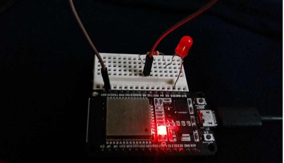
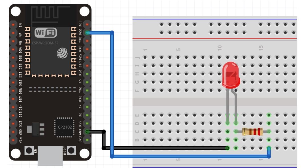
We can see that GPIO22 is connected with the anode pin of LED through a 220-ohm resistor (current limiting) and the cathode pin is connected with the common ground.
ESP32 MQTT Control Output Subscriber MicroPython Script
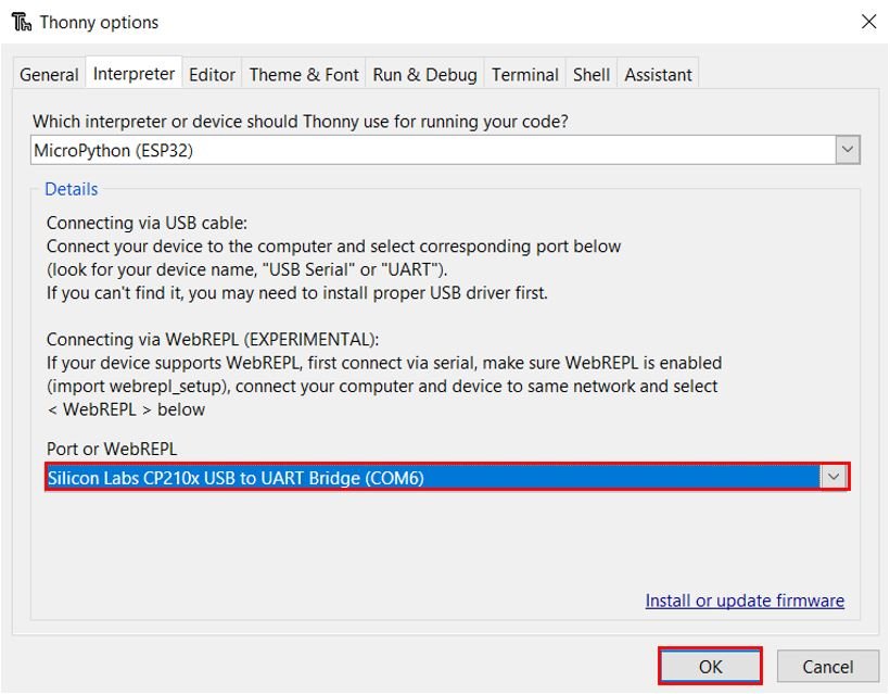
First of all, go to Tools > Options and select the Interpreter tab. Here select the COM port through which your second ESP32 board is connected. In our case it is COM6. Our first ESP32 board is connected with COM5.
As previously, we created the umqttsimple.py file for the ESP32 publisher board. Likewise we will follow all the same steps and create a similar file for the ESP32 Subscriber board as well. After we have installed the umqttsimple library for the second ESP32 board, then we will write our boot.py file followed by a main.py file.
boot.py
Open the boot.py file from your MicroPython device or create a new one if it is not present. Copy the code given below in that file and save it. You need to enter your network credentials and your Raspberry Pi IP address.
from machine import Pin
import time
from umqttsimple import MQTTClient
import ubinascii
import machine
import micropython
import network
import esp
esp.osdebug(None)
import gc
gc.collect()

led = Pin(22, Pin.OUT)

ssid = 'YOUR_SSID'
password = 'YOUR_PASSWORD'
mqtt_server = '192.168.10.8' #Replace with your MQTT Broker IP

client_id = ubinascii.hexlify(machine.unique_id())
topic_sub = b'esp32/led'

station = network.WLAN(network.STA_IF)
station.active(True)
station.connect(ssid, password)

while station.isconnected() == False:
  pass

print('Connection successful')
print(station.ifconfig())
How the Code Works?
The boot.py file for the second ESP32 is the same as that of the first ESP32. The only difference is that we are subscribing to the topic to which the first ESP32 board was publishing to.
topic_sub = b'esp32/led'Moreover, we will now configure the LED connected with GPIO22 as an output pin.
led = Pin(22, Pin.OUT) main.py
The next step is to create the main.py file for the ESP32 Subscriber. Create a new file and name it as main.py. Save it to the MicroPython device. Copy the code given below in that file.
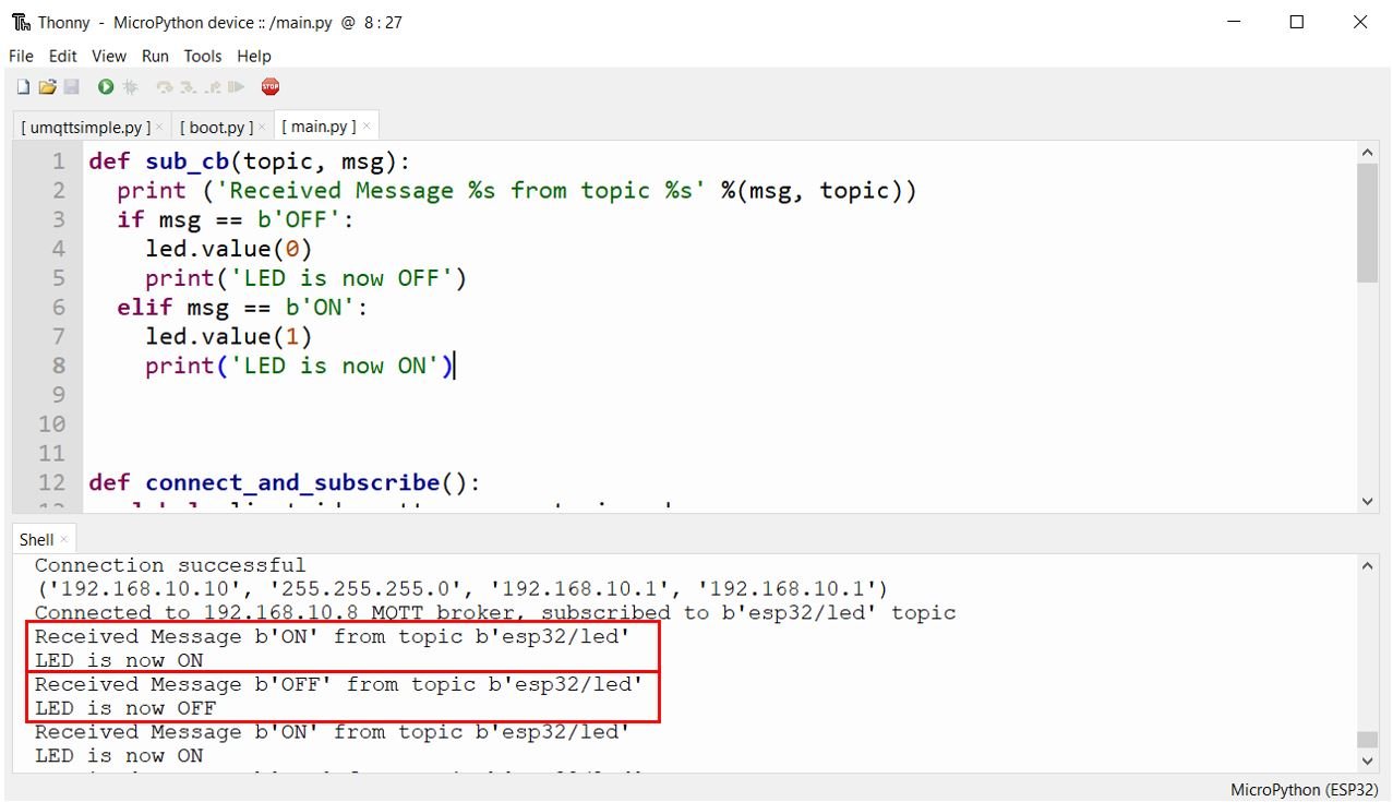
def sub_cb(topic, msg):
  print ('Received Message %s from topic %s' %(msg, topic))
  if msg == b'OFF':
    led.value(0)
    print('LED is now OFF')
  elif msg == b'ON':
    led.value(1)
    print('LED is now ON')

def connect_and_subscribe():
  global client_id, mqtt_server, topic_sub
  client = MQTTClient(client_id, mqtt_server)
  client.set_callback(sub_cb)
  client.connect()
  client.subscribe(topic_sub)
  print('Connected to %s MQTT broker, subscribed to %s topic' % (mqtt_server, topic_sub))
  return client

def restart_and_reconnect():
  print('Failed to connect to MQTT broker. Reconnecting...')
  time.sleep(10)
  machine.reset()

try:
  client = connect_and_subscribe()
except OSError as e:
  restart_and_reconnect()

while True:
  try:
       new_msg = client.check_msg()

  except OSError as e:
    restart_and_reconnect
How the Code Works?
We will first create a callback function which has two arguments. The first argument is the topic and the second one is the received message. This callback function displays the received message and the topic on the shell terminal. Then we will include if elif statements to check if the received message is OFF or ON. If the message is ON, then the LED will turn on. Likewise, if the message is OFF, then the LED will turn off. Relevant messages will be printed in the shell terminal.
def sub_cb(topic, msg):
  print ('Received Message %s from topic %s' %(msg, topic))
  if msg == b'OFF':
    led.value(0)
    print('LED is now OFF')
  elif msg == b'ON':
    led.value(1)
    print('LED is now ON')
Subscribing to Topic
Next, we will define the connect_and_subscribe() function. This is used to subscribe to the topic and also to connect with the MQTT broker. The next step is to initialize the MQTTClient() method with two parameters. The first parameter is the ID of the client named as: ‘client_id’ and the second parameter is the mqtt_server which is the IP address of the broker which was already configured in the boot.py file. This method will be assigned to the object ‘client.’ Then we will set the call back function to the client and connect that client with the broker. This would be done by using the connect() method on the object which we created previously: ‘client.’ Next, we will subscribe to topic_sub which we initialized in the boot.py file by using the MQTTClient object.
def connect_and_subscribe():
  global client_id, mqtt_server, topic_sub
  client = MQTTClient(client_id, mqtt_server)
  client.set_callback(sub_cb)
  client.connect()
  client.subscribe(topic_sub)
  print('Connected to %s MQTT broker, subscribed to %s topic' % (mqtt_server, topic_sub))
  return client
In case of failure of connecting with the ESP32 board, we will also create a restart_reconnect() function which would display a failure message on the screen. The ESP32 development board will restart after 10 seconds.
def restart_and_reconnect():
  print('Failed to connect to MQTT broker. Reconnecting...')
  time.sleep(10)
  machine.reset()
The next step is to connect our ESP32 board to the MQTT broker and also to subscribe to the topic. This is accomplished by forming a client. We will create a client through the connect_and_subscribe() function which we defined previously. Moreover, we have to keep track of a failure in connection as well. In case it happens, the ESP32 board will restart.
try:
  client = connect_and_subscribe()
except OSError as e:
  restart_and_reconnect()
The while loop runs endlessly and keeps track of any new messages which were received and stores it in the variable new_message. In case of a failure in connection, the ESP32 board would restart as we are calling the restart_and reconnect() function.
while True:
  try:
       new_msg = client.check_msg()

  except OSError as e:
    restart_and_reconnect
Uploading MicroPython Script
To upload this MicroPython script to your ESP32 subscriber device, go to Files and click on ‘Save as’ or click the Save icon. Save the file to the MicroPython device as main.py and click ok.
Now press the Run current script icon.
This would upload the code onto our ESP32 board. After the code is uploaded, press the Enable button on your ESP32.
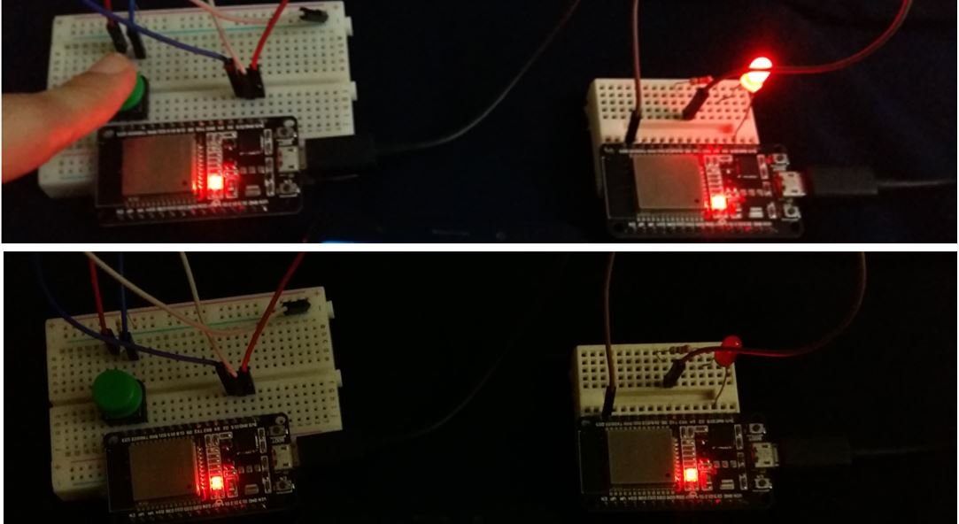
Open the Thonny Shell. The ESP32 board will first connect to the Wi-Fi and the MQTT broker and also subscribe to the esp32/led topic. Now press the push button and you can view “ON” message being received on the esp32/led topic and the LED turns on. When you release the push button, the message “OFF” is received on the esp32/led topic and the LED turns off.
Setting up Node-Red Dashboard as an MQTT Control Output Subscriber and Publisher
Now let us build the Node-Red Dashboard to publish the MQTT messages to the topic esp32/led and also subscribe to it.
We will be using Node-Red to publish and subscribe to the topics. However, you can use any other MQTT subscription service as well. In order to get started with Node-Red on Raspberry Pi, refer to the guide:
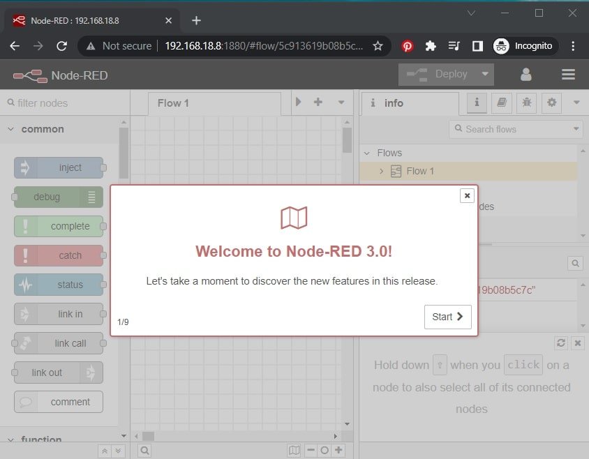
To access Node-RED, we need the IP address of our Raspberry Pi and the port number on which Node-RED is accessible. By default, it starts on port 1880. Open any web browser and enter the RPI IP address followed by the port number.
192.168.18.8:1880Creating Flow
This will open the Node-RED interface. You can start creating the flow.
Make sure the dashboard is already installed. Head over to the extreme right side and find dashboard.
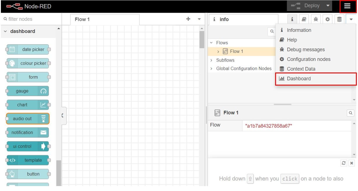
After you click it, the Dashboard tab appears. The first step is to create the tab. Head over to the Dashboard tab and click +tab to create a new tab. Specify the name and icon and click Update for the changes to take place. Here we are using icons from Angular Material Icons.
We will create one tab named Home.
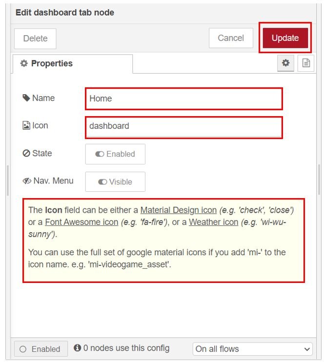
Note: You can use any name according to your preference but for the icon you have to use one available at these three links found below:
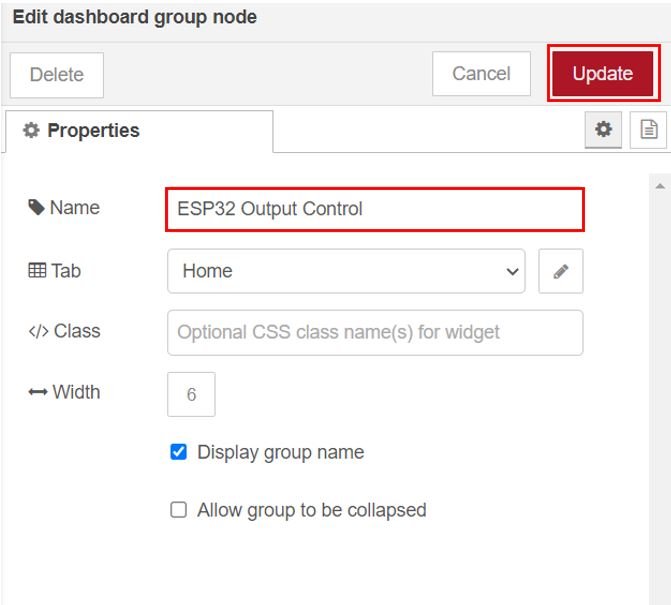
Add Widgets
The next step is to add the widgets. We will add one group to the tab. Click +group in the tab and create the group. We have named it ‘ESP32 Output Control.’
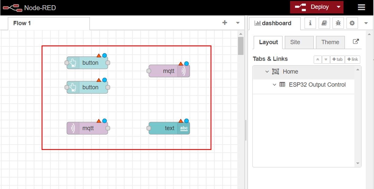
Add one mqtt in node and one text node to display the MQTT message. Add two buttons and one mqtt out node for publishing to the MQTT topic. Head over to the Nodes section found at the far left and scroll down to view the nodes under Dashboard. Drag and drop one text node, two button nodes, one mqtt in and one mqtt out node to the flow as shown below:
Publishing to MQTT Topic
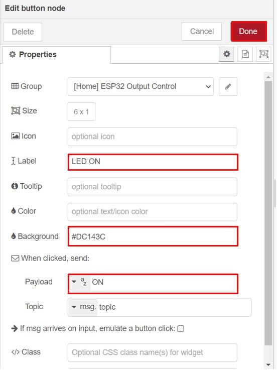
Now double click the first button node to edit its properties as shown below. This button will publish the message “ON” to the topic when it will be clicked.
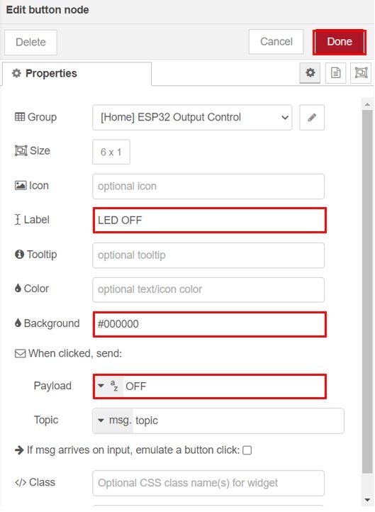
Now double click the second button node to edit its properties as shown below. This button will publish the message “OFF” to the topic when it will be clicked.
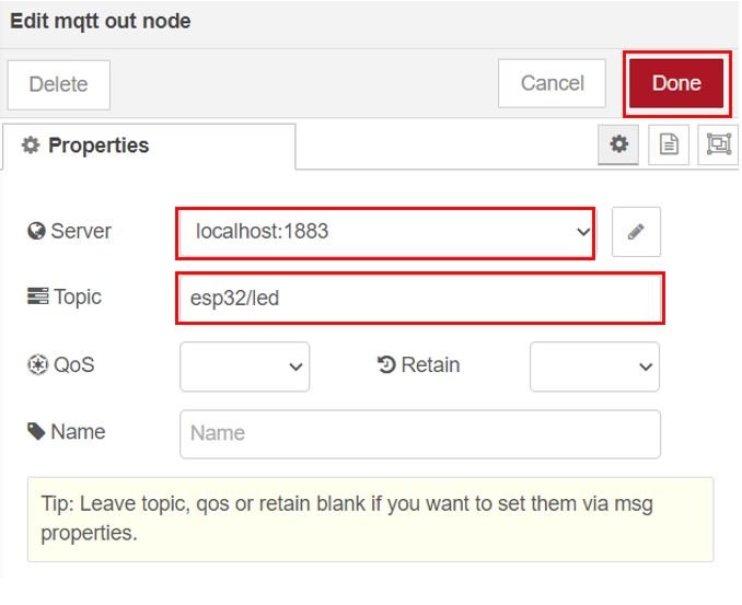
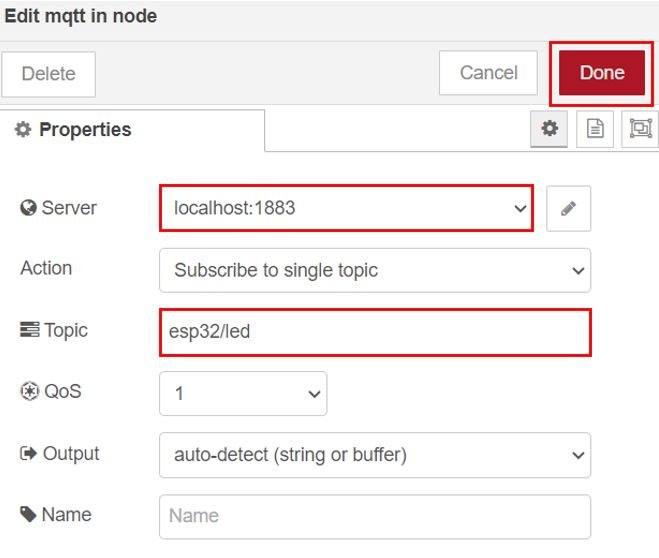
Edit the mqtt out properties as shown below. Here we have set the server (MQTT Broker) to localhost:1883 as we are using Mosquitto Broker on our Raspberry Pi. Specify the topic where we want to publish. Click the Done button.
Subscribing to MQTT Topic
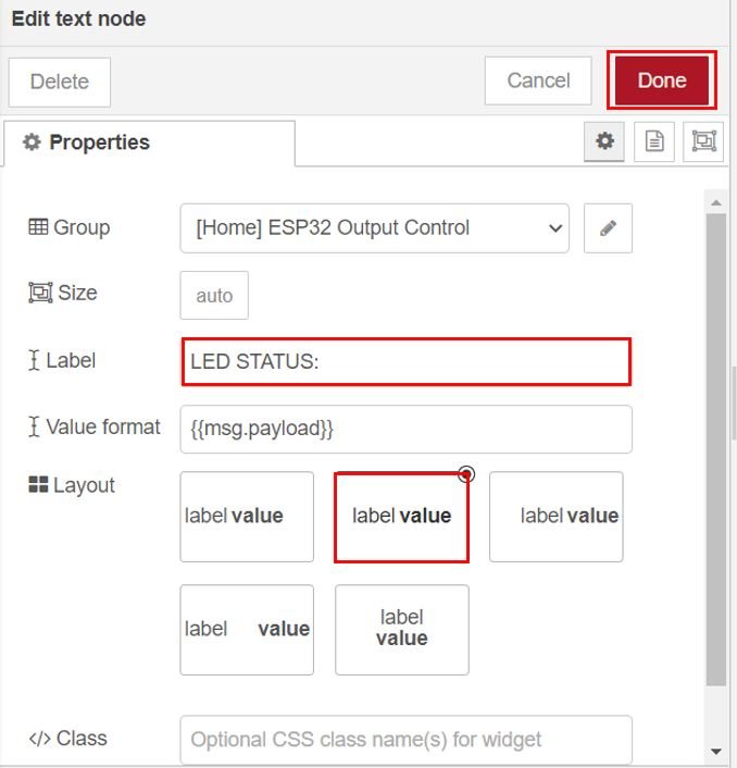
Next, we will add the topic subscription. Edit the properties of the text node as shown below:
Edit the properties of the mqtt in node as shown below. Here we have set the sever (MQTT Broker) to localhost:1883 as we are using Mosquitto Broker on our Raspberry Pi. Specify the topic to be subscribed. This node is being subscribed to the topic ‘esp32/led.’ Click the Done button.
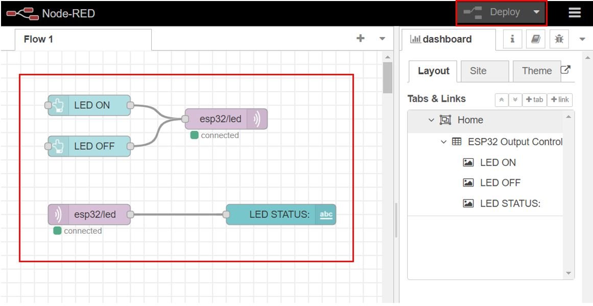
Finally wire the nodes as shown below. Now deploy the changes by clicking the Deploy button found at the top.
To view the UI, open a new web browser and type: http://Your_RPI_IP_address:1880/ui
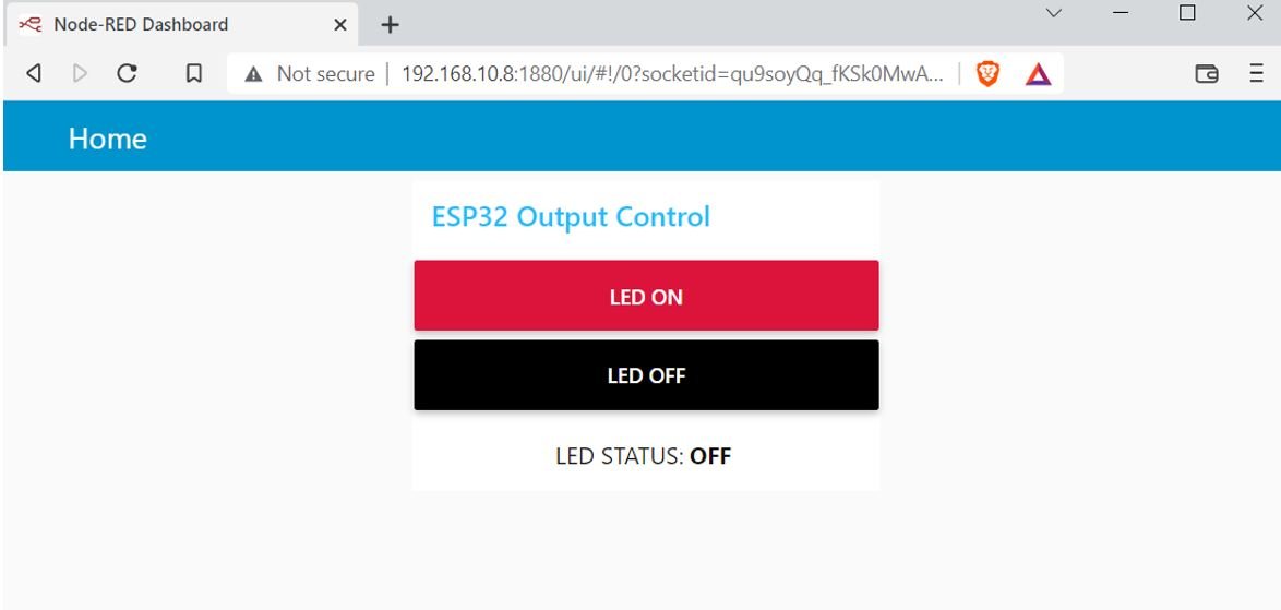
The user interface will open up once you press enter.
Here you can view the dashboard consisting of the two buttons and the LED status.
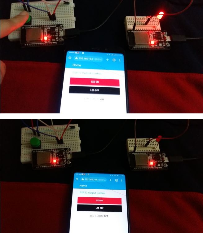
Testing
Now press the LED ON button and the LED connected with the ESP32 subscriber board will turn ON. Then press the LED OFF button and the LED will turn OFF. Additionally, the LED status will show ON or OFF according to the message received by Node-Red Dashboard. The LED status will update whenever you press/release the push button and whenever you click the LED ON and LED OFF buttons present on the Dashboard. This way we were able to set up multiple MQTT publishers and multiple MQTT subscribers using MicroPython and Node-Red.
Watch the video below:
Other ESP32 MQTT tutorials:
- ESP32 MQTT Publish Subscribe with Arduino IDE – Control Outputs
- ESP32 MQTT Publish Subscribe DS18B20 Readings with Arduino IDE
- ESP32 MQTT Publish Subscribe BME280 Readings with Arduino IDE
- ESP32 MQTT Publish Subscribe DHT22 Readings with Arduino IDE
- ESP32 ESP8266 MicroPython MQTT Publish DHT22 Sensor Readings