In this article, you will learn how to calculate the turns ratio of a ferrite core transformer for high-frequency switch mode power supply inverters. High-frequency ferrite core transformers are used in almost every power electronics circuit, such as inverters and pure sine wave inverters. They are used to boost up or step up the low DC voltage of a battery and other DC sources, like solar panels. Ferrite core transformers are also used in isolated DC to DC converters to step down or step up the DC voltage. For example, in an isolated buck converter, it is used to step down the DC voltage, and in an isolated boost converter, they are used to step up the DC voltage. In this article, we will learn how to calculate the turns ratio of a high-frequency ferrite core transformer with examples.
What is Ferrite Core Transformer?
A Ferrite Core Transformer is a type of transformer that uses a ferrite core instead of an iron core. Ferrite cores are made from a mixture of iron oxide and other metals, and they have unique magnetic properties that make them suitable for use in high-frequency applications. Ferrite core transformers are commonly used in power electronics circuits, such as inverters and DC to DC converters, to step up or step down voltage levels. They are known for their high efficiency and compact size, making them ideal for applications where space and energy efficiency are important.
Ferrite Core Turns Ratio Calculation
For example, in the boost-up stage we have two options to choose from in power electronics converters: push-pull topology and full bridge. I will explain both methods one by one. The turns ratio calculation formula and concept remain the same for both topologies. The only difference between the push-pull topology and the full bridge transformer design is that the push-pull ferrite core transformer requires a center tap in the primary winding. In other words, the push-pull transformer has twice the number of primary turns than the full bridge transformer.

Push-pull topology ferrite core turns ratio calculation with examples
Let’s start with an example. For example, we want to design a 250-watt boost-up DC-to-DC converter. We are using push-pull topology for this design. We are using a 12-volt battery and we want to step up the DC voltage from 12 volts to 310 volts. The switching frequency of the design is 50 kHz. We are using an ETD39 ferrite core which can handle 250 watts. It is beyond the scope of this topic to explain how to select a ferrite core according to the power rating. I will try to write a separate article on it. The output of the ferrite core will always be a high-frequency square wave of 50 kHz. We need to use a full rectifier to convert it into a DC voltage of 310 volts. You may also need to use an LC filter to remove harmonics or AC components from the output.
Ferrite Transformer Primary Turns Calculation
As you know, battery voltage does not remain the same all the time. As the load on the battery increases, the battery voltage will be less than 12 volts. With no load and a fully charged battery, the battery voltage will be near 13.5 volts. Therefore, the input voltage is not constant, and we must consider it while calculating the turns ratio of the ferrite core transformer. The cutoff voltage for the battery is usually 10.5 volts. We can take it as the smallest possible value of the input voltage to boost up the DC converter. So, we have the following parameters now:
Vinput = 10.5 volt
Vout = 310 volt
As we know that formula of turns ratio calculation in transformer is
N = Npri / Nsc = Vin / Vout
Where Npri is the number of primary turns and Nsc is the number of secondary turns. We have three known variables like turns ratio, which can be calculated by the above equation, input voltage, and output voltage. But we need to calculate the primary turns to find the secondary turn of a ferrite core transformer. The formula to calculate the primary turns for a ferrite core transformer is given below:
Npri = Vin * 10^8 / 4 * f * Bmax * Ac
But for push-pull, it will be half the number of turns compared to the primary.
- Where Npi is the primary number of turns, Vin(nom) is the normal input voltage which, in our example, is 10.5 volts.
- Bmax is the maximum flux density. The unit of maximum flux density is Gauss. Remember, if you are using Tesla as the unit for maximum flux density, Bmax = 10^4 Gauss. The value of maximum flux density is usually given in the data sheet of the ferrite core. We usually take the value of Bmax between 1300G to 2000G. This is usually an acceptable range for all ferrite core transformers. Note: A high value of flux density will saturate the core, and a low value of flux density will lead to underutilization of the core. For example, we will take 1500G for the DC to DC converter.
- f is the switching frequency of the converter. In our example, the switching frequency of the DC to DC converter is 50 kHz.
- Ac is the effective cross-sectional area of the ferrite core. We have to refer to the data sheet for this value. In this example, we are using the ETD39 core. The effective cross-sectional area of the ETD39 is 125 mm^2 or 1.25 cm^2.
We have all the values to calculate primary number of turns .i.e.
Vin = 10.5 volt, Bmax = 1500G, f = 50 KHz, Ac = 1.25 cm^2By putting these parameters in two above formula, we can calculate turns primary number of turns.
Npri = 12 . 10^8 / 4 . 50000 . 1500 . 1.25 = 3.2
Hence Npri = 3.2, but we cannot use fractional turns. So we need to round off the calculated value of primary turns to the nearest whole number, which is 3. The primary number of turns for the ferrite core is 3. However, before that, we need to check whether for Npri = 3, Bmax is within the acceptable range or not. As mentioned above, the acceptable range for Bmax is 1300-2000G. But the question is, why do we need to check the value of Bmax again? This is because we adjusted the value of primary turns from 3.2 to 3. So let’s calculate the value of Bmax for Npri = 3 using the above formula.
Bmax = Vin * 10^8 / 4 * f * Npri * Ac
Bmax = 12 * 10^8 / 5 * 50000 * 3 * 1.25 = 1600G
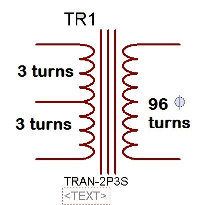
So the calculated value of Bmax is 1600G, which is within the acceptable range of the maximum flux density. This means we can take Npri = 3 for further calculations. The primary number of turns for the push-pull ferrite center-tap transformer is 3 turns + 3 turns. In any design, you will need to adjust the value of Npri if it is in fraction. You can easily adjust it. But you need to check the value of Bmax every time. We start with an assumed value of Bmax and calculate Npri. But you can also start with an assumed value of Npri and check the value of the maximum flux density Bmax. For example, suppose a value of Npri = 1 and check the value of Bmax, and keep repeating this process until it falls within an acceptable range.
Ferrite Transformer Secondary Turns Calculation
Now let’s move to the secondary turn of the ferrite core. In our design, the output of the DC to DC converter is 310 volts at any input voltage. The input voltage is variable from 10.5 volts to 13.5 volts. We will need to implement feedback to regulate the output voltage to 310 volts. Therefore, we will use a slightly higher value for the output voltage so that even at the minimum input voltage, we can still achieve an output voltage of 310 volts by adjusting the duty cycle of the PWM. So, we should design a ferrite core transformer with a secondary rated at 330 volts. The feedback mechanism will dynamically adjust the output voltage by varying the duty cycle of the PWM. Additionally, you should consider losses and voltage drops across switching devices while designing the transformer.
So, the transformer must be able to supply a 330-volt output with an input range of 13.5 volts to 10.5 volts. The maximum duty cycle for PWM is 98%, leaving the remaining 2% for dead time. During the minimum possible input voltage, the duty cycle will be at its maximum. At a maximum duty cycle of 98%, the input voltage to the transformer is 0.98 * 10.5 = 10.29 volts.
By using voltage ratio formula of transformer = voltage ratio = 330 / 10.29 = 32.1. Voltage ratio and turns ratio in transformer is equal to each other. Hence N = 32.
So we know all values to calculate secondary turns of ferrite core transformer.
N = 32, Npri = 3
Nsec = N * Npri = 32 *3 = 96
So the number of primary turns is equal to 3, and the number of secondary turns is equal to 96. This is all about the turns ratio calculation for high-frequency transformers. If you have any issues, please let me know in the comments.
You may also like to read:
- Design Three Phase Inverter using Simulink MATLAB
- Multilevel inverter design Using Pic Microcontroller
- three phase sine wave inverter using pic microcontroller
- Three Phase Five Level Inverter simulation using Simulink MATLAB
- DsPIC33F microcontroller based pure sine wave inverter
- single phase pure sine wave inverter using arduino
- Three phase sine wave inverter using Arduino
- Solar Inverter using SG3525 PWM Controller IC
Dear bilal malik
how can we calculate ferrite core inductor for buck converter
i will post a article on it soon
What different is Gauss and Guass?
chech this post http://microcontrollerslab.com/output-inductor-design-calculation-smps/
How to get the design frequency
During primary turns calculations we took so many things in consideration but why not in secondary
Assala-mu-alaikum .Can you give a full diagram of an inverter circuit using ferrite core transformer. 100w to 300w range will be fine.
you can purchase the design from shop contact me at microcontrollerslabhub@gmail.com
aslam o alikum sir
dear sir,
i’m confused according ti ferrite core transfomer calculation.
sir i have
Ferrite core selected for Transformer: E 65/32/27
Area of ferrite core Ae = 540 mm2
Max flux density Bm = 0.1 Wb/m2
(for push-pull configuration)
Air gap = 0
but i did not macth result according to your calculation
sir
Vin =12,f=40khz,Ac=5.4cm2,Bmax =1500G but in result just 1 Np turn require but i,m using 3 turn in Np and 106 for Ns
whats happen with me
did you multiply Vin by 10^8?
use the formula
Npri= Vin * 10^8 / 4 * f * Bmax * Ac
use multiple wires for the primary for higher amps. just 1 turn will give you 12v input
Sir i respect your efforts
Formula given for high frequency or ferrite transformer is only for input output voltage .
But what about input output current ,gauge of wire, size of ferrite core available.
I would be thankful if provide information for the same.
I’m really grateful for this beautiful piece, pls can u explain how pwm can be controlled in sg3525 chip.. and also how to fix the pin 1 and pin 2 voltage to obtain a nice result as regard to your ferrite feedback compensation calculation. does it mean dat d sg3525 chip must oscillate with 98percent @ all time before the regulation is perfected. I dnt understand these pls. i’d be highly appreciated if u respond quickly sir. thanks
Hi there colleagues, nice article and good arguments commented here,
I am genuinely enjoying by these.
Nice work man…plz,how do we determine the guage of the pry and secondary Windings?
I will try to post a article on it soon or you can find a table for wire gauge selection on google images its not that hard
Hi Bilal God bless you; Good article, congratulations; today I was reading all the article about the calculation of number of turns for primary and secondary in high frequency transformers; yesterday I removed a chopper transformer from a tv switching power supply and removed its windings to rewind it again; But I just wanted to build an easy switching power supply to get familiarized with it; the problems is that I don’t know what kind of ferrite core is; that means its size measurement.
Hi ! I need to a flyback transformer which can convert from 50Vdc to 5Vdc. Also, output will be 5 ampere. How can I chose ferrite core (ETD29,39,49) and calculate primary and secondary turns ?
Hi Bilal,
May I have the link to reliable resource and calculations on how to select wire gauge size for center taped inverter winding?
Dear Sir,
Tell me how to take output current into account.
As i want to calculate turns for 48V, 5A DC to DC converter.
Thank You
Sir this is a great way you have made it clear n simple but i want to ask one question and that is
In the formula for nprim calculation
We are using SI units for voltage flux and bmax but and we are using cm’2 for area rather we should use m’2
Dear Sir,
your article is great and easy to understand for transformer design and i have one of doubt, how to select different types of inductor likes (drum, toroidal core etc.) for circuit designing.
sir can you please help me i have problem on finding flux density of core i have following details
capacity of transformer: 25 KVA
core loss to be mantained at : 70 watt
size of l.t winding = 2.5*6.5
no of turns L.t =100( 25 turns per layer)
size of H.t winding= swg 22( total turns = 5001 and 205 turns per layer)
Dear Sir,
Very nice topics and also helpfull for all.
But I have one question . Pri. & Sec. weir gauge calculation will be as conventional way ,like as iron core transformer ?
dear, how can i calculate inductor for 2 phase 180 degree out of phase buck converter and frequency with duty ratio.
Asalam o alekom.. thanks for the great and wonderful lecture.. i was stuck in it from long time cous i am not a electronic engineering student… 🙂 i am doing by my own.. so thanks for the help ALLAH bless u and one more thing.. plzz share with us calculation of wire gauge # for the P. and S winding
Please I want to know the calculations of the toroidal ferrite core , thank you
Respected sir,
I want to select ferrite core for my high frequency transformer design.
Ratings are:
Vin(primary)=115V
Vout(sec)=230V
frequency= 10khz/20khz
turns ratio=2
Iin=5A
Iout=2.5A
Please help me for designing and selection of ferrite core
Thanks for this article;it was usefull,..sir u said the output of the ferrite transformer will always be 50kHz in the given example, what if the load operates on 50 or 60 Hz wont it be a problem?? If yes, please what are the necessary changes??
thanks a lot for your good article , i enjoyed it
May i use ferrite core for h bridge inverter
I/p V, 7V, o/p V, 220V 80Hz.
Switching frequency 16Khz
hi malik
thanks for the post
I have an issue with the calculation for Npri
my core is EE65 and the Ac is 5.3cm2 by observation.
now, after I calculated for Npri using Vpx10^8/4BmaxAcF which you gave, my result is 0.75471698turns
I feel something is wrong with this calculation
can you please help me with what I am missing?
thanks
please provide all values. Also have you checked and mentioned switching frequency and voltage?
But if you have assumed the Bmax value and Frequency as mentioned in this post then maybe it will make difference with your real number of turns of your transformer.
Hi,
In the beginning, you wrote:
N = Npri / Nsc
And while finding Nsec you wrote:
Nsec = N * Npri = 32 *3 = 96
HOW the formula changed???
Isn’t it should be: Nsec = Npri / N
???
You answer seems right but the formula is confusing me.
Please explain.
(CONT.)
Well, it should be:
Voltage Ratio = Vin / Vout = 10.29 / 330
Voltage Ratio = 0.03118
Voltage ratio and turns ratio in transformer is equal to each other. Hence N = 0.03118.
So we know all values to calculate secondary turns of ferite core transformer
N = 32, Npri = 3
N = Npri / Nsec
Or, Nsec = Npri / N = 3 / 0.03118 = 96.2155
So, Nsec = 96 (after rounding off)
This seems right way to me. But in your case you reciprocaled both formulas.
**Error correction on previous comment:
N = 0.03118, Npri = 3
How can this calculation be applied to EE65 ferrite core transformer.
My calculation seem not to work.
I feel I am missing something
Hi Excellence,
Since you have not provided all the values, let us assume Bmax = 1500 G, Switching Frequency f = 50KHz. Also Effective Area ( Ac ) of EE65 Ferrite core is 540mm^2 or 5.4cm^2 (As per datasheet https://www.tme.eu/es/Document/e9623be7fcdb459866403325c39d6a24/e653227.pdf ). Now put the Vin value in this formula to calculate Npri :
Npri = (Vin * 10^8) / (4 * f * Bmax * Ac).
After calculating Npri you may check Bmax value (if you wish). Then follow those steps and use the formula I have mentioned above in my comment. And if you are facing problems, let me know with more details next time. Have a nice day 🙂
Thanks very much replying me.
And sorry for giving little details.
My concern is this:
After employing the formulae for the calculation, my Np is less than 1.
Here is the breakdown:
12 ×10^8/4×50,000×1500×5.4
My result is 0.74074074 which is less than 1 turn
This looks too little for Primary Turns
Am I still missing something?
Please help me
Its okay 🙂 Happy to help as I am learning too. Are you sure that the Vin you wrote 12V in the formula is actually what you are applying? Is it step-up?
I am certain sir. Its 12v
I intend using it for step up
I actually wanted to use it for Inverter using Switch Mode Topology.
I will be glad if you can give me some practical hints concerning that too.
Its my first attempt.
well, I am not professional in this either. Just leaning as you are. I can’t do practicals but can discuss and maybe sort out the problem. In this case I can’t find out because there can be many cases like:
Case 1 : Your input supply is is greater than 12V
Case 2 : Your switching frequency is lower than 50KHz
Case 3 : Core type is different.
Please counter-check all these things. But unlike all these, Bmax seems ok to me. (You can assume minimum value i.e. Bmax = 1300 too if you like)
Considering Case 1 (which I don’t think should be greater than 12V in your case but let’s try): Let us assume your input supply is 20v. Keeping rest all values untouched. After putting this value in the formula we get Npri = 1.2 ~ 1 [Though this seems wrong to me but it is greater than 0].
Consider Case 2 : Lets us assume little more than minimum switching frequency i.e. f = 25Khz (just half of previous frequency). So, Npri = 2.4 or 2 (after rounding off).
Consider Case 3 : If your core is different then the cross section area may also differ. It could be same too or maybe higher or smaller to 540mm^2. Only in case when it is smaller can result to non-zero primary turns.
Overall, it is important to check all those parameters I suppose because the formula is ok. Hope you find some practical help.
Practically, the more high the frequency, the size of transformer is small.
very good conversation guys (Y)
Okay
If the higher the core size, the lower the frequency, then could it be possible that the core is supposed to operate at the 20kHz to at least get tangible Np using Vp=12v, and maintaining the Bmax=1300
For example:
12×10^8/4×20,000×1300×5.4 = 2.14turns = 2turns approx
But, my question is that what will be the consequence of using 20kHz instead of 50kHz?
Thanks for your responses
**Error correction on previous comment:
N = 0.03118, Npri = 3
I am certain sir. Its 12v
I intend using it for step up
I actually wanted to use it for Inverter using Switch Mode Topology.
I will be glad if you can give me some practical hints concerning that too.
Its my first attempt.
copper wire size calculations
hi.
i have a question. does the size core has any effect on selecting the bmax value?
I’m using a ee85 core and trying to calculate a high output current transformer(about 2-4kA & 2-5 volt).
some websites say the value of bmax should be between 3500G t 4500G.
what should i do??? help plz..
my design:
f=30khz – vin=310vdc – v out- 3- 5volt – IOut max= 4000A – ee85
SIr,
Can you provide Complete calculations of DC-AC Ballast design T/F and Resonant inductor
Ballast 4W, Input 12Vdc, Push-Pull config.
Hi dear friend
thanks about this post. it’s great
Can you create a post about calculating the number of the wire(wire layer) and the effect of the skin?
with this post’s example.
thanks a lot.
Is it possible to design 4000Watt SMPS inverter from 500VDC input to 220VDC,15A output.
Regards,
Prasada Rao
Hello
I want to design a switching power supply with the following specifications
Topology : Forward or Flyback
Vin (AC) = 220V
Vin (Diode Bridge DC) = 310V
Iout = 13A
EER42/42/20 => Ac = 1.94 cm^2
Bmax = 1500G
Fsw = 45KHz
Thank you for helping me
Very good read. For a full bridge topoplogy it’s the same set of equation for push pull?
You seem to neglect the joule heating losses / coils resistances that will reduce the output voltage at the full charge ?
how to calculate in direct ac-ac high frequency link transformer?
After design the L and No.of. turns, how to calculate the copper wire size…?
Pls I need a pwm circuit for ferrite core using 3205irf. And tl494ic
Thanks so much I made an inverter using sg3524 ..I got an output of 320v on no load but once I place a load of 26watts d voltage drop to 150v..one side of the MOSFET is also heating Dan d other..d ferrite core I used is removed from a factory inverter and slated to handle not less Dan 500watts load
It is a great article for me. I want to design a step up transformer of 120W, output 1000V. How do I select the ferrite core.. Please help me..
Dear friend
this article is so interesting and is what I searched for(calculating the ferrite transformer), but realy i’m not sure whether i can use it in my choice or not?
please let me describe my request,
I want to calculate and design a pulse transformer to drive two back to back tied thyristors gate , my input is a pulse with power suply of 5 volt and 50 Hz line cycle and duty of 100 us puls. and the gates drive, need 3 volt with approx 150 mA (I think beter to choos 500 mA),
there is some limitation on space i have to place the transformer which the Height is 15 mm maximum.
would you please help me to find my answer,
Can ferrite cores be used at 2500 Hz frequency in a high power matching Transformer ?.
If yes can any one share details.
Which winding should wind clockwise and which should wind counter clock wise on ferrite Cor smps transformer to receive 32vdv,5Amp dc output from240v input
Hi, please what do you mean by 98% duty cycle is it 49% for each switch?
Good Work… Just one doubt
The effective cross sectional area of ETD39 is 125mm^2 or 1.25cm^2.
or
The effective cross sectional area of ETD39 is 12.5mm^2 or 1.25cm^2.
Please I need your help, and what will it take me, I need circuit on amplifier, inverter, charge controller and how to calculate ferrite core.
Hi So if voltage is secondary is higher the primair we need to calculate N like this sec/prim?
if primary is higher voltage then secondary then we need to calculate N is Prim/sec?
If this is true I did it wrong.