In this user guide, we will learn how to control a DC motor with ESP32/ESP8266 in MicroPython by using an L298N motor driver. We will introduce you to the L298N motor driver module and then we will use it to learn some basic control of the dc motor including start, stop, backward and forward motion through our ESP development boards.

We have similar guides for ESP32, ESP8266, and Arduino using Ardino IDE:
- Interface L298N DC Motor Driver Module with ESP32
- Interface L298N DC Motor Driver Module with ESP8266 NodeMCU
- Interface L298N DC Motor Driver Module with Arduino
Prerequisites
Before we start this lesson make sure you are familiar with and have the latest version of MicroPython firmware installed in your ESP boards and have a running Integrated Development Environment (IDE) in which we will be doing the programming such as uPyCraft IDE or Thonny IDE.
- Getting Started with uPyCraft IDE on ESP32 and ESP8266
- Getting Started with Thonny MicroPython IDE for ESP32 and ESP8266
If you want to use VS Code, you can follow this guide:
- MicroPython ESP32 and ESP8266: Program with VS Code and Pymakr
- Flash MicroPython Firmware with esptool.py to ESP32 and ESP8266
L298N Motor Driver Module
Dc motors can be controlled through several drivers which are widely available in the market. For this project, we will be using L298N motor driver module as it very easy and relatively inexpensive as well. It is widely used in controlling robots as we can connect up to four motors at once but if we want to control the speed and direction as well than it allows two motors to be connected. Thus, it is perfect for two wheeled robots. This module is mainly used in robotics and in controlling dc and stepping motors.
The L298N motor driver module consists of a L298N motor driver IC ,78M05 5V regulator, 5V jumper enable, power LED, heat sink, resistors and capacitors all combined in an integrated circuit. The diagram below shows all the components consisting inside the module.
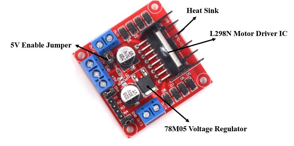
The L298N Motor driver IC is powerfully built with a big heat sink. It is a dual channel H bridge motor driver which can be easily used to drive two motors.
The module also has a 78M05 5V regulator which is enabled through a jumper. Keeping the jumper intact, means the 5V regulator is enabled. If the motor power supply is less than 12V then we will power the module through the voltage regulator. The 5V pin in this case acts as an output to power the microcontroller. If the power supply is more than 12V, make sure the jumper is not intact and supply 5V power through the pin separately.
Note: If the jumper is connected, do not supply power to both the motor power supply input and the 5V power supply input.
Specifications
The table shows some specifications of the L298N motor driver module:
| Driver Model | L298N |
| Driver Chip | Double H-bridge L298N |
| Maximum Power | 25W |
| Maximum Motor Supply Voltage | 46V |
| Maximum Motor Supply Current | 2A |
| Driver Voltage | 5-35V |
| Driver Current | 2A |
| Size | 43x43x26mm |
PinOut
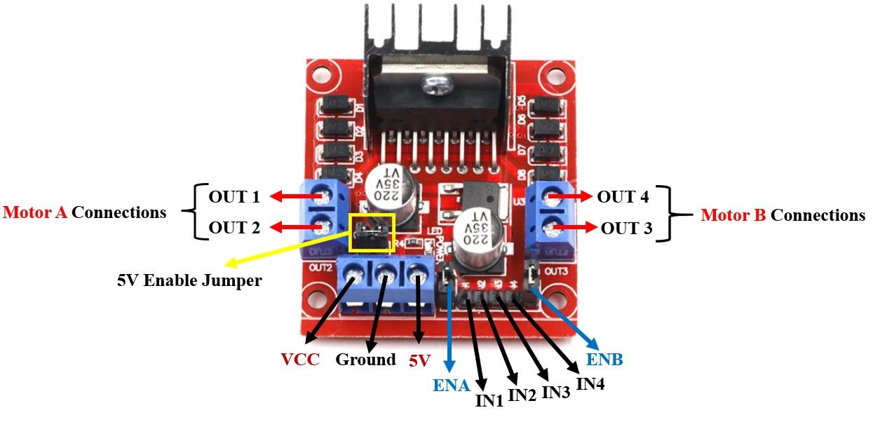
Let us now look at the pinout of the module.
| Pin Name | Description |
| VCC | This is the pin which supplies power to the motor. It is imprinted with +12V on board but can be powered between 6-12V. |
| Ground | This is the common ground pin. |
| 5V | This pin supplies the power (5V) for the internal circuit (L298N IC). Will be used only if the 5V enable jumper is not intact. If jumper is intact, then it acts as an output pin. |
| ENA | This pin controls the speed of the motor A by enabling the PWM signal. |
| IN1 & IN2 | These are the input pins for motor A. They control the spinning direction for that particular motor. |
| IN3 & IN4 | These are the input pins for motor B. They control the spinning direction for that particular motor. |
| ENB | This pin controls the speed of the motor B by enabling the PWM signal. |
| OUT1 & OUT2 | OUT1: Positive terminal. OUT2: Negative terminal These are the output pins for motor A. Motor A having voltage between 5-35V, will be connected through these two terminals. |
| OUT3 & OUT4 | OUT3: Positive terminal OUT4: Negative terminal These are the output pins for motor B. |
Controlling DC motors through L298N module and MicroPython
Let us now see the details behind controlling the dc motor through the L298N module.
Control Pins
There are two types of control pins found at the bottom right side of the module. One type controls the speed and the other type controls the direction of the motor.
Speed Control (ENABLE) Pins
The speed control pins labelled ENA and ENB on the module, control the speed of the dc motor and turn it ON and OFF.
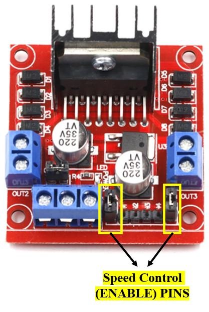
ENA controls the speed of motor A and ENB controls the speed of motor B. If both of the pins are in a logic HIGH (5V) state, then both the motors are ON and spinning at maximum speed. If both of the pins are in a logic LOW (ground) state, then both the motors are OFF. Through the PWM functionality we can also control the speed of the motor. By default, there is a jumper connected on these pins which keeps these pins in a HIGH state. In order to control the speed, we need to remove the jumper and connect these terminals with the PWM pins of ESP32/ESP8266 and program them in code. The table below demonstrates the logic signals required for controlling Motor A.
| ENA Pin State | Motor Action |
| 1 (HIGH) | ON |
| 0 (LOW) | OFF |
If ENA is in a HIGH state, the motor is enabled and if it is in a LOW state then the motor is off.
Direction Control (INPUT) Pins
The direction control pins are the four input pins (IN1, IN2, IN3, IN4) on the module.
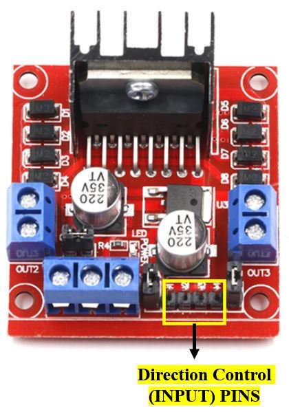
Through these input pins we can determine whether to move the dc motor forward or backwards. IN1 and IN2 control motor A’s spinning direction whereas IN3 and IN4 control motor B’s spinning direction. The table below shows the logic signals required for the appropriate spinning action for motor A.
| IN1 | IN2 | Motor Action |
| 1 (HIGH) | 1 | OFF |
| 1 | 0 (LOW) | Backward |
| 0 | 1 | Forward |
| 0 | 0 | OFF |
As seen from the table, whenever one of the inputs is in a HIGH state (5V) then the motor will spin. Otherwise, when both the inputs are LOW (ground) state or both are in HIGH state then the motor stops. In order for motor A to spin forward, IN1 should be LOW and IN2 should be HIGH. For backwards motion, IN1 should be HIGH and IN2 should be LOW. Motor B is also controlled in a similar way.
Interfacing DC Motor & L298N motor Driver with ESP32 and ESP8266
Now, as we have seen how to control the dc motor through the motor driver, let us do a demonstration by incorporating our ESP boards. You will need the following equipment.
Required Equipment
- ESP32/ESP8266 development board
- L289N Motor driver Module
- Mini DC Motor
- One 9V battery
- 0.1uF capacitor
- One Switch
- Connecting Wires
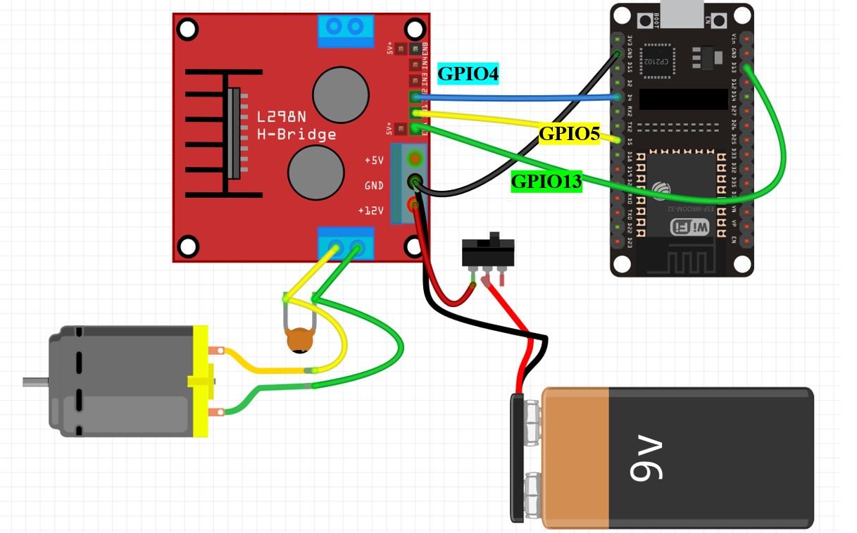
Assemble the circuit as shown in the connection diagram below.
For ESP32:
For ESP8266:

We will be using motor A output pins to control this motor. Thus, ENA will set the speed and IN1 and IN2 will set the spinning direction of the motor. For both ESP32 and ESP8266 we have chosen similar GPIO pins to connect with the driver. GPIO13 is connected with ENA. GPIO5 and GPIO4 are connected with IN1 and IN2 respectively. You can choose appropriate GPIO pins when connecting the ESP board and the driver module together.
The dc motor is rated at 6-12V, and requires a large amount of current to start. This is why we will be using an external power source for the dc motor. As we can use any power source ranging from 6-12V, we will incorporate a 9V battery in our case. You can use any other power source as you please. We are using a slider switch connected with the 9V battery supply which is very helpful in cutting the power supply. This way we can turn the driver on and off without connecting and disconnecting wires manually. We have also connected a capacitor with the two terminals of the dc motor so that there are no abrupt voltage spikes. You do not need to include the switch and the capacitor as they are optional but they increase the functionality of the project.
Creating L298N Motor Driver Library in MicroPython
Now, as we have connected all our equipment together let us write the microPython code to control the dc motor.
- We will first create a dcmotor module to make the code easier to implement by using a single command.
- Inside the module we will create a class: DCMotor.
- The DCMotor class will further have methods assigned to it.
- We will initialize the motor with three parameters:
- Pin1 (IN1)
- Pin2 (IN2)
- enable (ENA)
The two pins will act as output pins and the enable will act as a pwm pin. We will create a DCMotor object called ‘motor’ and initialize it in the following way:
motor = DCMotor (Pin1, Pin2, enable)
- Lastly, we will use methods of the DCMotor class namely: forward(), backwards() and stop() on the DCMotor object ‘motor’ to control the dc motor.
MicroPython Script: dcmotor Module
Copy the following code in a new file and save it as dcmotor.py.
class DCMotor:
  def __init__(self, pin1, pin2, enable_pin, min_duty=750, max_duty=1023):
        self.pin1=pin1
        self.pin2=pin2
        self.enable_pin=enable_pin
        self.min_duty = min_duty
        self.max_duty = max_duty

  def forward(self,speed):
    self.speed = speed
    self.enable_pin.duty(self.duty_cycle(self.speed))
    self.pin1.value(0)
    self.pin2.value(1)

  def backwards(self, speed):
        self.speed = speed
        self.enable_pin.duty(self.duty_cycle(self.speed))
        self.pin1.value(1)
        self.pin2.value(0)

  def stop(self):
    self.enable_pin.duty(0)
    self.pin1.value(0)
    self.pin2.value(0)

  def duty_cycle(self, speed):
   if self.speed <= 0 or self.speed > 100:
        duty_cycle = 0
   else:
    duty_cycle = int(self.min_duty + (self.max_duty - self.min_duty)*((self.speed-1)/(100-1)))
    return duty_cycle
Now, we will look at how to upload the dc motor MicroPython library to ESP32 and ESP8266. This step is required because MicroPython itself does not contain the L298N library. Follow the steps in order to successfully upload the library to ESP32/ESP8266 in uPyCraft IDE:
- First, in the Tools section, click on the NEW FILE button and open a file.

- Then replicate the above given microPython dc motor L298N library in that file.
- Name the file dcmotor.py and save it by choosing your desired directory.

- Now press the button DOWNLOAD AND RUN in the tools section.

As soon as you click on the download and run button, you will get the message that states “download ok”. Moreover, you will also see dcmotor.py file lists under the device menu.
You have now successfully uploaded the L298N motor driver MicroPython library to ESP32/ESP8266 using uPyCraft IDE. After that, we can use the above library functions to control DC motor movement. You can use a similar procedure to upload files using Thonny IDE.
Uploading L298N Motor Drive Library in Thonny IDE
If you are using Thonny IDE, open a new file and copy the code as we did in uPyCraft IDE.
- Save the file as dcmtor.py
- In addition, head over to Device> Upload Current Script with Current Name
In the latest version of Thonny IDE, you will get the option to save the library to a device when you click on the save as option.
You have successfully uploaded the L298N motor driver library to ESP32/ESP8266 using Thonny IDE.
How the Code Works?
We are creating a class called DCMotor and defining it. We will initialize the _init_ constructor which is often used in object-oriented programming. This method will be called when we will create an object of the DCMotor class. This constructor initializes the attributes of the class. We will specify four parameters inside this constructor: pin1, pin2, enable_pin, min_duty, max_duty.
- pin1 corresponds to the GPIO pin connected with IN1 (input 1). This is GPIO5 in our case.
- pin2 corresponds to the GPIO pin connected with IN2 (input 2). This is GPIO4 in our case. Both these pins are configured as outputs.
- enable_pin is the GPIO PWM pin connected with ENA (Enable of motor A).
- min_duty is the minimum duty cycle which is required for the motor to start. This can be changed according to the frequency required for the motor to spin and is set to 750 as default.
- max_duty is the maximum duty cycle required to start the motor. It is set to 1023 as default. This can also be changed according to the frequency.
class DCMotor:
  def __init__(self, pin1, pin2, enable_pin, min_duty=750, max_duty=1023):
        self.pin1=pin1
        self.pin2=pin2
        self.enable_pin=enable_pin
        self.min_duty = min_duty
        self.max_duty = max_duty
forward()
Then we will define the forward() method. This will cause the dc motor to move forward. As we saw earlier, the dc motor spins forward whenever IN1 goes in a LOW (0) state and IN2 goes in a HIGH (1) state. This means that we have to set pin1 to 0 and pin2 to 1 to achieve this forward motion.
  def forward(self,speed):
    self.speed = speed
    self.enable_pin.duty(self.duty_cycle(self.speed))
    self.pin1.value(0)
    self.pin2.value(1)
backwards()
Next, we will define the backwards() method. This will cause the motor to spin backwards. The dc motor moves backward whenever IN1 is HIGH (1) and IN2 is LOW (0). Thus, we will be setting pin1 to 1 and pin2 to 0 to achieve the backward motion.
  def backwards(self, speed):
        self.speed = speed
        self.enable_pin.duty(self.duty_cycle(self.speed))
        self.pin1.value(1)
        self.pin2.value(0)
stop()
To stop the motor, we will define the stop() method. The motor will stop when pin1,pin2 and the duty cycle of the enable_pin is set to 0.
  def stop(self):
    self.enable_pin.duty(0)
    self.pin1.value(0)
    self.pin2.value(0)
Controlling Speed
To control the speed of the dc motor we will also be defining the duty_cycle. It takes in two parameters: self and speed. This method calculates the duty cycle based upon the speed (0-100) of the motor. 0 is the minimum speed(motor off) and 100 is the maximum speed. We are using an if-else statement inside the method definition. Whenever the speed is out of the bound of 0-100 then the duty cycle is set to zero. Otherwise, it calculates the duty cycle based upon the minimum and maximum duty.
  def duty_cycle(self, speed):
   if self.speed <= 0 or self.speed > 100:
        duty_cycle = 0
   else:
    duty_cycle = int(self.min_duty + (self.max_duty - self.min_duty)*((self.speed-1)/(100-1)))
    return duty_cycle
MicroPython Script: main.py to control DC Motor
Create a new file and save it main.py. This will contain all your main code which will execute the controlling aspect of the machine by importing the dcmotor module and calling the constructor. Make sure to save both the dcmotor.py and main.py in the same directory.
from dcmotor import DCMotor
from machine import Pin, PWM
from time import sleep
frequency = 15000
pin1 = Pin(5, Pin.OUT)
pin2 = Pin(4, Pin.OUT)
enable = PWM(Pin(13), frequency)
dc_motor = DCMotor(pin1, pin2, enable)
dc_motor = DCMotor(pin1, pin2, enable, 350, 1023)
dc_motor.forward(50)
sleep(10)
dc_motor.stop()
sleep(10)
dc_motor.backwards(100)
sleep(10)
dc_motor.forward(60)
sleep(10)
dc_motor.stop()
How the Code Works?
We start off by importing the dcmotor module which we created previously. Instead of writing repetitive commands, with a single command we will be able to control the motor. We will also import the pin and pwm classes from the machine module as we have to deal with both. Sleep class will help in causing delays between each transition. We will be using the functionalities we described above of the dcmotor module and use them in controlling the dc motor.
We are initializing pin1 and pin2 as output pins each connected with GPIO5 and GPIO4 respectively. The enable pin is the PWM pin on GPIO13 with the set frequency as 15000. Next, we are initializing the DCMotor object called ‘dc_motor’ and giving it the access of IN1, IN2 and ENA. To move the motor forward and backwards we will use their respective methods which we already defined inside the dcmotor module. We will specify different values of speeds between 0-100 and pass this as the parameter inside the methods. For example, the following code causes the motor to spin backwards at maximum (100) speed then spin forward with a speed of 60 and then stopping. All of this happens with a delay of 10 seconds between each transition.
dc_motor.backwards(100)   #motor spins backwards
sleep(10)         #delay of 10s
dc_motor.forward(60)
sleep(10)
dc_motor.stop()
Demo
To test the MicroPython script for DC motor with ESP32 and ESP8266, upload the main.py file to ESP32/ESP8266. After uploading the MicroPython script, click on Enable/Reset button of ESP32 or ESP8266:


Video Demo:
Other MicroPython tutorials for ESP32 and ESP8266:
- MicroPython HC-SR04 Ultrasonic Sensor with ESP32 and ESP8266
- OLED Display with ESP32 and ESP8266 in MicroPython
- MicroPython: BME680 Web Server with ESP32 and ESP8266 (Gas, Pressure, Temperature, Humidity)
- ESP32/ESP8266 ADC with MicroPython – Measure Analog Readings
- Push Button with ESP32 and ESP8266 using MicroPython – Control an LED
- ESP32 and ESP8266 GPIO Programming with MicroPython – LED Blinking Example
Copied and pasted both files, dcmotor.py and main.py. With reference to the line (enable = PWM(Pin(18), frequency) , I get the error – “function takes 1 positional argument but two were given”. Can you help with this.
Thanks
Please make sure, you are using ESP32 and have the latest version of ESP32 MicroPython firmware flashed to it. If you don’t know how to flash firmware to ESP32, you can follow this guide:
https://microcontrollerslab.com/flash-micropython-firmware-esptool-py-esp32-esp8266/
We just tried this code again and it is working fine for us.
Thankyou very much for the response. It works fine for me on ESP32 using both the L298N and the TB6612FNG. When I use the same code on a Raspberry Pi Pico, I get that error.
Please use this for raspberry Pi Pico:
https://microcontrollerslab.com/dc-motor-l298n-driver-raspberry-pi-pico-tutorial/
How did you arrive at the number 750 for the in the line – def __init__(self, pin1, pin2, enable_pin, min_duty=750, max_duty=1023): ?
Why not 0 – 1023?
That is a good question, and I am not the author. I did find this when I was thinking about it. https://docs.micropython.org/en/latest/esp8266/tutorial/pwm.html
My conclusion is that you want to have for this case a minimum defined speed of around 75% all the time, and then ramp to max. That said 0 to 1023 is valid just 0 would mean the the minimum is basically stopped so you wouldn’t move and to do that you could just basically send a stop to both pins forward and reverse pins to acheive no movement. A minimum of 0 is not really required to hold at that point of the pwm. Now if you are doing something with a precise PWM need like always moving forward and then quick stop on the motor that would be a cycle between say I want to go 750 for a second then 0 for a second then repeat until desired result.
Thank you for posting this HowTo. I modified your example to control two latching-type watering valves, which needed “forward” and “reverse” to get them to change state.