MPPT charge controller techniques optimize the generation of solar power by ensuring that the operating voltages of solar panels are close to the maximum power point under changing environmental conditions. Solar panels have non-linear current-voltage characteristics that vary with environmental changes, making it challenging to maximize power generation. MPPT techniques play a crucial role in achieving efficient power conversion by adapting to variations in light levels, temperature, and other panel characteristics.
What is the need for MPPT techniques?
MPPT (Maximum Power Point Tracking) techniques are essential in solar power generation for several reasons:
- Optimizing Power Generation: Solar panels have non-linear current-voltage characteristics that change with environmental conditions such as temperature and light levels. MPPT techniques ensure that the operating voltages of the solar panels are kept close to the maximum power point, where the panels can generate the most power. This optimization helps maximize the overall power output of the solar system.
- Adapting to Environmental Variations: Environmental factors like changes in sunlight intensity and temperature affect the performance of solar panels. MPPT techniques continuously monitor and adjust the operating conditions of the panels to adapt to these variations. By dynamically tracking the maximum power point, MPPT techniques enable the solar system to efficiently generate power even with changing environmental conditions.
- Higher Efficiency: MPPT techniques improve the overall efficiency of the solar system. By ensuring that the solar panels operate at their maximum power point, the system can convert a higher percentage of the available solar energy into usable electrical power. This increased efficiency translates to more electrical energy being generated from the same amount of sunlight, resulting in improved system performance and higher energy yields.
- Maximizing Return on Investment: Solar power systems can be a significant investment. MPPT techniques help maximize the return on investment by optimizing power generation. By efficiently converting sunlight into electrical energy, solar systems with MPPT technology can generate more power over their lifespan, resulting in greater cost savings and a faster payback period.
In summary, MPPT techniques are needed in solar power systems to optimize power generation, adapt to environmental variations, increase system efficiency, and maximize the return on investment. These techniques play a crucial role in ensuring the efficient operation of solar systems and maximizing the utilization of solar resources.
Most Common MPPT Charging Methods
There are several MPPT techniques for a PV system, which include Fuzzy Logic Control, Neural Network, Fractional open circuit voltage, Fractional short circuit current, and so on. But the two most commonly used techniques are mentioned below:
- Perturb and Observe (P&O – also known as the hill-climbing method)
- Incremental Conductance (InCond)
Although both techniques have their merits and demerits, like all other MPPT techniques, the main advantage of these two is their simplicity and ease of implementation.
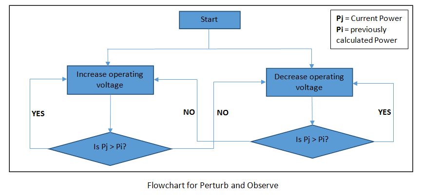
MPPT PERTURB AND OBSERVE (P&O) Method
In this method, the voltage and current of the solar panel are measured initially, and hence the corresponding power ‘Pi‘ is calculated. The operating voltage of the panel is then perturbed (∆V), and the resulting power ‘Pj‘ is compared with the previously calculated power ‘Pi‘. The difference between the two determines the direction of further required changes in the current and voltage values.
If the difference between the two power values is positive, i.e., ‘Pj‘ is greater than ‘Pi‘, the perturbation is considered to be in the correct direction. Therefore, the voltage and current are kept changing in the same direction until the power starts to decrease. On the other hand, if this difference results in a negative value, then the next perturbation should be in the opposite direction. This process continues until the maximum power point is reached.
The main disadvantage of the P&O method is that, at a steady state, the algorithm is unable to realize that it has actually reached the maximum power. Instead, the operating point starts to oscillate around the maximum power point. Also, it is observed that under rapidly changing atmospheric conditions, the algorithm may end up perturbing in the wrong direction.
MPPT Incremental Conductance Method
In this algorithm, the maximum power point is determined by comparing two quantities: instantaneous conductance (I/V) and incremental inductance (∆I/∆V). The algorithm exploits the fact that at the MPP, the slope of the power-voltage curve is zero.

How it Overcome the Limitations of the Perturb and Observe (P&O) Method?
One of the most widely used maximum power point tracking (MPPT) algorithms in photovoltaic (PV) systems is the Incremental Conductance (IncCond) method. This algorithm overcomes one of the major drawbacks of the Perturb and Observe (P&O) method, i.e., instead of oscillating around the maximum power point, the incremental conductance method can determine when it has actually reached the maximum power point. This makes it a more efficient and accurate technique for tracking the maximum power point of a PV system.
How does it Work?
The basic idea behind the incremental conductance method is to compare the instantaneous change in power (dP) with respect to the change in voltage (dV) at each sampling instant. By continuously monitoring the power and voltage, the algorithm can determine the direction in which the power is increasing or decreasing. This allows it to make adjustments to the operating voltage in order to reach the maximum power point (MPP).
Once the maximum power point is reached, the incremental conductance algorithm maintains the system at this instant unless the current (I) changes. In case of any change in the current, whether due to variations in solar irradiance or temperature, the algorithm adjusts the operating voltage accordingly to track the new maximum power point.
Advantages
One of the advantages of the incremental conductance method is its ability to deal with rapid climate changes in an efficient manner. For example, if there is a sudden change in solar irradiance, the algorithm can quickly respond and adjust the operating voltage to track the new maximum power point. This makes it particularly useful in environments with variable weather conditions.
However, it is important to note that the incremental conductance method requires more complex circuitry compared to the Perturb and Observe method. The algorithm relies on accurate measurement of both power and voltage, as well as precise calculations to determine the incremental conductance. This complexity may increase the cost and complexity of the MPPT system.
Overall, the incremental conductance method is a powerful and effective technique for maximum power point tracking in photovoltaic systems. It offers improved accuracy and efficiency compared to the Perturb and Observe method, especially in dynamic weather conditions. While it may require more advanced circuitry, the benefits it provides make it a popular choice for MPPT in PV systems.

Other Maximum Power Point Tracking (MPPT) Techniques
There are several other Maximum Power Point Tracking (MPPT) techniques besides Perturb and Observe (P&O) and Incremental Conductance (InCond). Some of these techniques include:
- Fractional Open Circuit Voltage: This technique estimates the open circuit voltage by analyzing the ratio between the voltage at the maximum power point and the open circuit voltage, allowing for more accurate tracking.
- Fractional Short Circuit Current: Similar to Fractional Open Circuit Voltage, this method estimates the short circuit current by analyzing the ratio between the current at the maximum power point and the short circuit current.
- Fuzzy Logic Control: Fuzzy Logic Control utilizes a fuzzy rule-based system to determine the changes in voltage and current based on input variables such as solar radiation and temperature.
- Neural Network: Neural Network-based MPPT algorithms use artificial neural networks to approximate the maximum power point based on training data. These algorithms can adapt well to varying environmental conditions.
- Constant Voltage (CV): The Constant Voltage method maintains a constant voltage across the solar panel to ensure that the power output is optimized.
- Fractional Open Circuit Voltage / Fractional Short Circuit Current combined method: This technique combines the Fractional Open Circuit Voltage and Fractional Short Circuit Current methods to achieve improved accuracy and tracking efficiency.
It’s important to note that different MPPT techniques have varying levels of complexity, accuracy, and implementation requirements. The selection of the most suitable technique for a specific application depends on factors such as system requirements, available resources, and cost considerations.
Conclusion
In conclusion, MPPT charge controller techniques are essential for optimizing the generation of solar power by ensuring that the operating voltages of solar panels are close to the maximum power point under changing environmental conditions. The two most commonly used methods, Perturb and Observe (P&O) and Incremental Conductance (InCond), offer simplicity and ease of implementation. However, each method has its own advantages and disadvantages. P&O may result in oscillations and perturbations in the wrong direction, while InCond overcomes this issue but requires more complex circuitry. Additionally, there are other MPPT techniques available, such as Fractional Open Circuit Voltage, Fractional Short Circuit Current, Fuzzy Logic Control, Neural Network, Constant Voltage, and combinations of these methods. The choice of the most suitable technique depends on specific system requirements and available resources. Overall, MPPT techniques play a crucial role in achieving efficient power conversion and maximizing solar power generation.
Related content:
I need MPPT with microcontroller, do you have?
Hi Mr Bilal ,
i need an expert to program fuzzy logic based MPPT algorithm inside the DSP micro controller. if you can help please send me email at ehsanm360@gmail.com
contact me at microcontrollerslabhub@gmail.com
i want to ask about the circuit diagram of MPPT charge controller ,can you help me to get it