Modified Sine Wave Inverter Using Pic Microcontroller

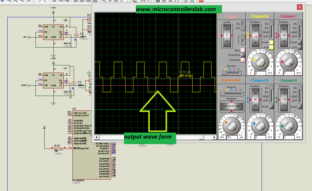
output of modified sine wave inverter

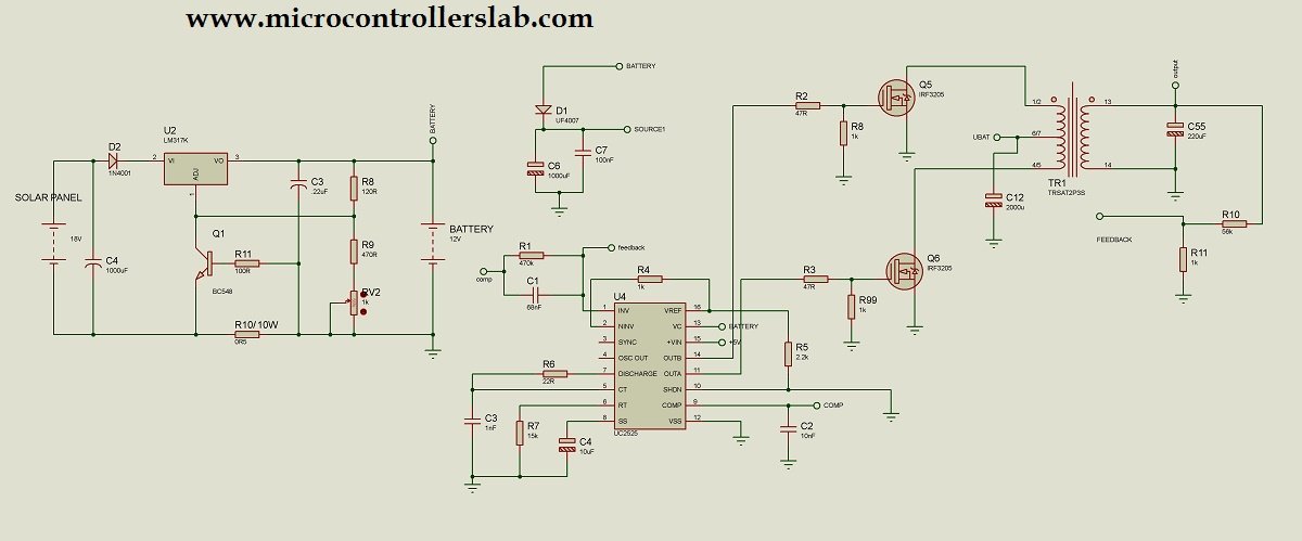
A modified sine wave inverter is designed by utilizing a PIC microcontroller and a push-pull topology. The push-pull configuration operates MOSFETs as switches and a control circuit controls them to produce a stepped-up battery voltage with a modified sine wave form. The control signal is generated by the PIC16F87A microcontroller. At the end of this … Read more

Pure Sine Wave Inverter Circuit Diagram

Sine wave inverter circuit diagram with a complete step-by-step program and coding. In this article, we will discuss how to use a push-pull converter, sinusoidal pulse width modulation, an H-bridge, and a low-pass LC filter to create a pure sine wave inverter circuit diagram. I have already discussed all of these topics in the following … Read more

SPWM Generation using PIC16F877A Microcontroller

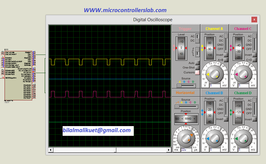
SPWM sample

We will discuss how to use a microcontroller to generate sinusoidal pulse width modulation. We will explore the usage of SPWM signals as gating signals to the MOSFETs of an H-bridge in order to obtain a clean and precise sine wave output. By incorporating an LC filter, we can further enhance the quality of the … Read more