Electronics Projects for Engineering Students

Electronics projects circuits for engineering students

Electronics projects for electronics engineering students; This page contains a list of hundreds of electronics projects to learn electronics. Starting from basic level electronics projects to complicated electronics projects, many electronics engineering students want to learn electronics and are very passionate about learning electronics by doing some electronics projects in university. Mostly, students work on … Read more
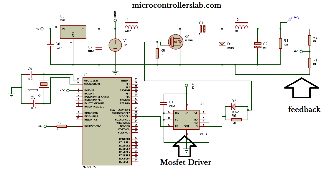
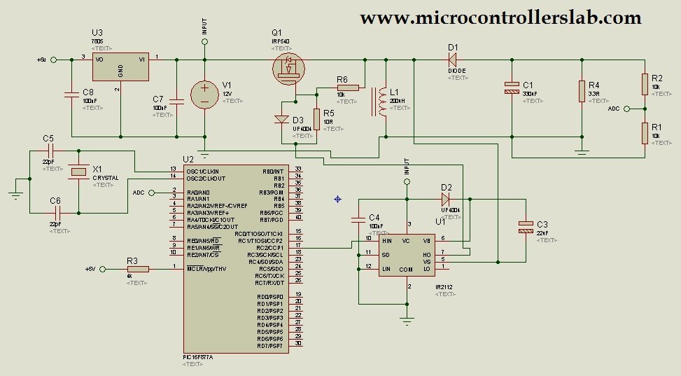
Cuk converter circuit design using pic microcontroller

cuk converter circuit diagram usig pic microcontroller and IR2110

Cuk converter circuit design using pic microcontroller, In this article I am going to write about cuk conveter circuit design and its implementation using pic microcontroller. Cuk converter works similar to buck boost converter but in cuk converter output voltage polarity is opposite to that of input voltage polarity. I have already posted articles on … Read more

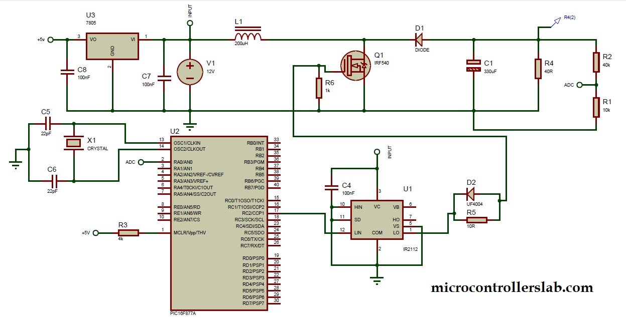
Buck Boost Converter with Pic Microcontroller and IR2110

circuit diagram of buck boost conveter using IR2110

Buck-Boost converter with PIC microcontroller and IR2110. In this article, I am going to write about the Buck-Boost converter. What is a Buck Boost converter? How to design a Buck-Boost converter? How to use the MOSFET driver IR2110 to drive the high-side switch or MOSFET? What are the applications of the Buck-Boost converter? How to … Read more

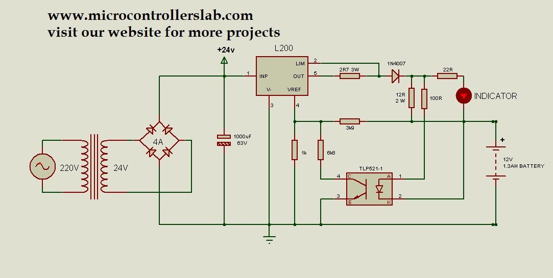
12 Volt 1.3AH Battery Charger Circuit Diagram

12 volt 1.3AH Battery charger

The 12-volt 1.3AH battery charger circuit diagram is a highly practical design that utilizes the L200 voltage regulator and an over-voltage protection circuit. It employs an optocoupler to provide feedback, allowing precise control of the voltage across the battery by efficiently toggling the L200 voltage regulator on and off. This circuit diagram is an excellent … Read more

Boost converter using IR2110 and pic microcontroller

circuit diagram of boost dc to dc converter using pic microcontroller

Boost converter using IR2110 and pic microcontroller, In this article I am going to post my design of boost converter ? In this article, you will learn what is boost converter? How to design boost converter? How to use MOSFET as a switch in boost converter and how to drive this MOSFET which is connected … Read more

Transformer less power supply for microcontrollers

Schematic of transformerless power supply

Transformer less power supply for microcontrollers, in this article you will learn how to design transformer less power. Applications of Transformer less power supply. Cost analysis of commonly used power supplies and transformer less power supplies. Applications of Transformer less power supply: Transformer less power supply is suitable only for low power applications. For example … Read more

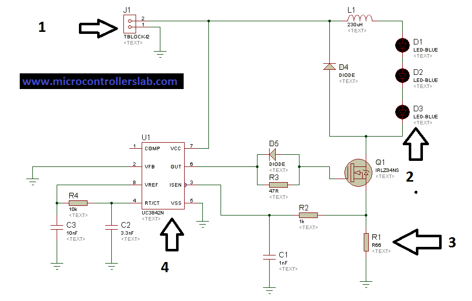
LED Driver using UC3842 PWM Controller IC

Circuit diagram of solar LED driver using UC3842

LED drivers are essential components in the world of lighting, enabling the efficient and reliable operation of LED systems. In this article, we will delve into the world of LED drivers, exploring their purpose, applications, and the various configurations in which LEDs can be arranged. With a specific focus on the series configuration, we will … Read more

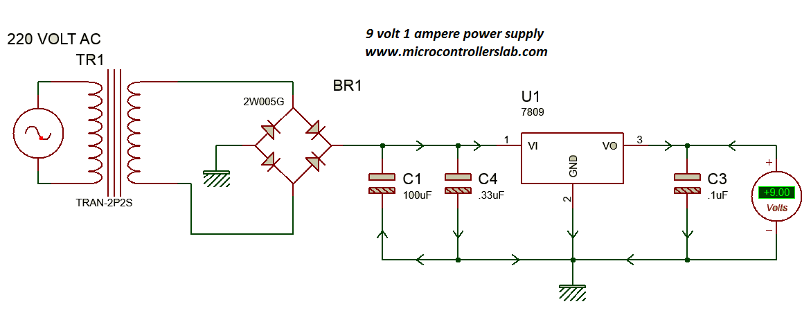
Power Supply for Electronics Projects

Circuit diagram of 9 volt and 1 Ampere power supply

This article focuses on a widely-used regulator that serves as a power supply in numerous electronics projects, microcontroller-based projects, and embedded system projects. It is particularly beneficial for engineering students who may not have access to expensive power supplies but still wish to delve into the field of electronics and utilize them effectively within their … Read more

Pure Sine Wave Inverter Circuit Diagram

Sine wave inverter circuit diagram with a complete step-by-step program and coding. In this article, we will discuss how to use a push-pull converter, sinusoidal pulse width modulation, an H-bridge, and a low-pass LC filter to create a pure sine wave inverter circuit diagram. I have already discussed all of these topics in the following … Read more