Buck-Boost converter with PIC microcontroller and IR2110. In this article, I am going to write about the Buck-Boost converter. What is a Buck Boost converter? How to design a Buck-Boost converter? How to use the MOSFET driver IR2110 to drive the high-side switch or MOSFET? What are the applications of the Buck-Boost converter? How to use the PIC microcontroller to generate PWM and duty cycle to turn on and turn off the MOSFET or switch for a specified time. Let’s start with a basic introduction to the Buck-Boost converter.
What is a Buck-Boost Converter?
A buck-boost converter is a power electronics non-isolated voltage regulator. The output of a buck-boost converter is either less than or greater than the input voltage to the converter. Basically, a buck-boost converter combines the functionalities of the buck converter and the boost converter. However, the output voltage polarity of the buck-boost converter is opposite to that of the input voltage. A simple circuit diagram of the buck-boost converter is shown below.
How Buck-Boost Converter Works?
Here’s a basic explanation of how a Buck-Boost converter works:
Topology
A Buck-Boost converter typically consists of an inductor, a switching transistor (usually a MOSFET), a diode, and a capacitor. The circuit configuration allows the converter to operate in both buck and boost modes.
Operating Principle
Buck Mode (Step-Down)
During the buck mode, the input voltage is higher than the desired output voltage. The switching transistor is turned on, connecting the input voltage to the inductor. The inductor stores energy.
When the transistor is turned off, the inductor discharges and the diode allows the current to flow to the output capacitor and load. The output voltage is lower than the input voltage.
Boost Mode (Step-Up)
Conversely, during the boost mode, the input voltage is lower than the desired output voltage. The switching transistor is turned on, and energy is stored in the inductor.
When the transistor is turned off, the inductor discharges and the diode prevents current from flowing back to the input. The output voltage is higher than the input voltage.
Control and Regulation
The duty cycle of the switching transistor is controlled to regulate the output voltage. A feedback loop compares the output voltage to a reference voltage, adjusting the duty cycle to maintain a stable output.
Buck Boost Converter Applications
There are many applications of a buck-boost converter. Some of them are given below:
- Maximum power point tracking of solar charge controller
- Voltage regulators
- LED drivers and many others
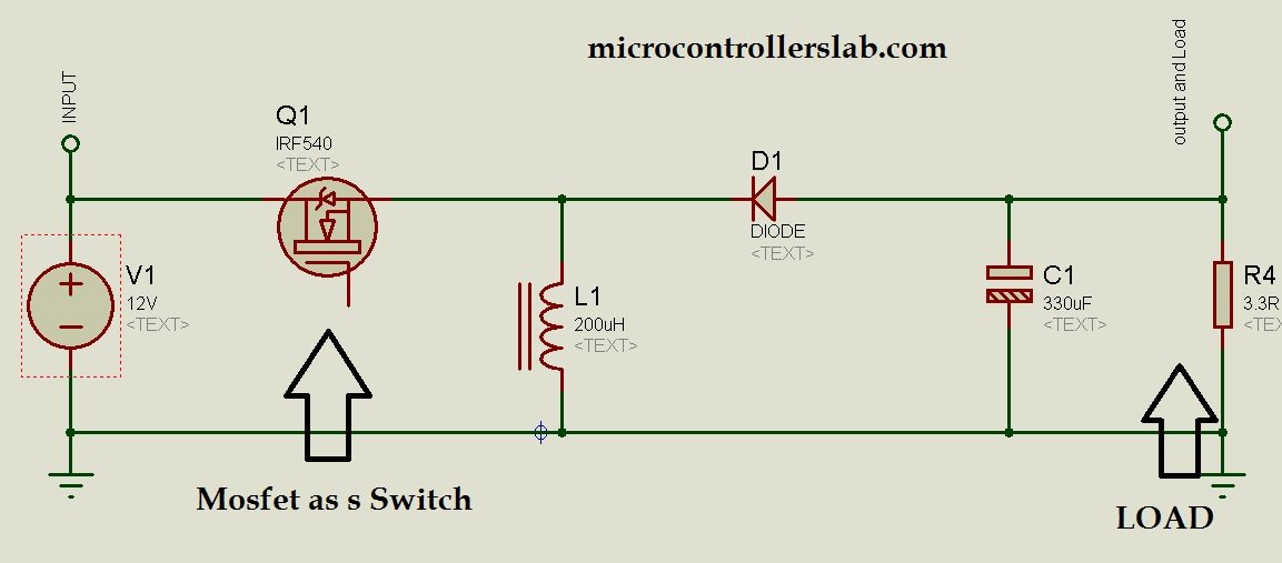
Practical Buck-Boost Circuit Diagram
A simple circuit diagram of a buck-boost converter is given above. But for practical implementation, you need many other things with it. For example, in the above circuit diagram, a MOSFET is used as a switch. MOSFET can be used either as a low-side switch or a high-side switch. If the load is connected to the source pin of the MOSFET, it is called a high-side switch. If the load is connected to the drain pin of the MOSFET, it is called a low-side switch. In the case of a buck-boost converter, the load is connected with the source pin of the MOSFET, so it is being used as a high-side switch. Therefore, you need a high-side MOSFET driver to drive the MOSFET.
There are many dedicated MOSFET driver ICs available in the market. You can use any of them. I have used the IR2110 MOSFET driver, which can be used either as a low-side MOSFET driver or a high-side MOSFET driver. If you want to know about what is a MOSFET driver? How to use a MOSFET driver as a low-side driver or high-side driver? How to use IR2110 as a low-side MOSFET driver and high-side MOSFET driver? Read the following article.
All switch mode regulators work by changing the duty cycle of PWM. You can change the output voltage by changing the duty cycle of PWM. If you don’t have an idea about PWM (pulse width modulation) and duty cycle, I recommend you to read the following article. This article explains what is pulse width modulation. What is the duty cycle? How to use the PIC16F877A microcontroller to change the duty cycle and how to set the frequency of pulse width modulation.
Circuit diagram of buck-boost converter:
The circuit diagram of a buck-boost converter is shown below. In this circuit diagram, a resistor at the end is used as a load. PIC16F877A microcontroller is used to generate pulse width modulation using pic microcontroller. You can calculate the values of the inductor and capacitor according to your requirements.
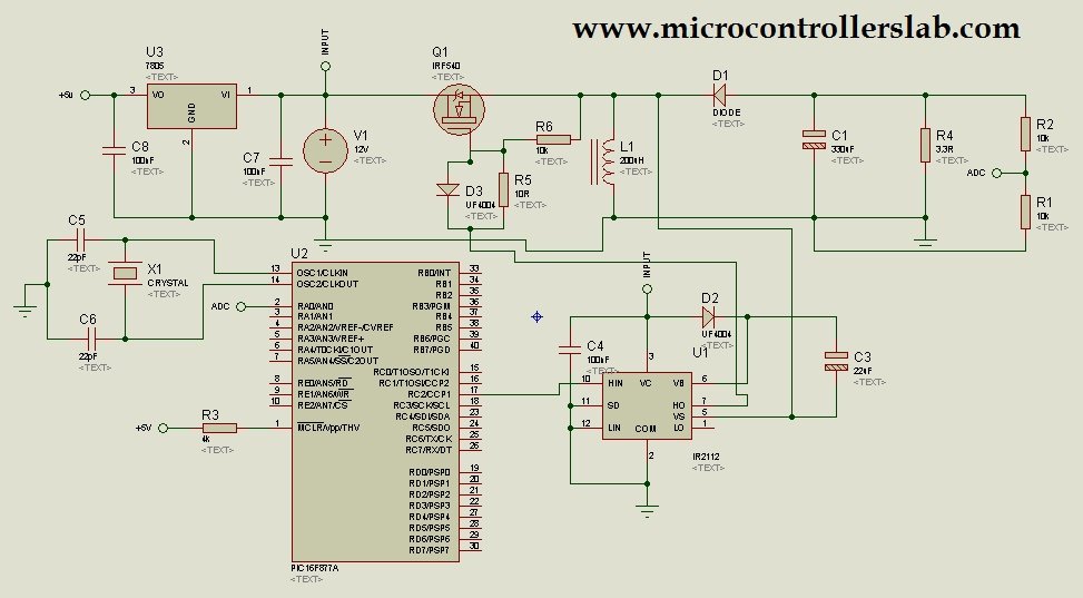
In the above circuit diagram, a voltage divider is used at the output to decrease the voltage to less than 5 volts. This is because the microcontroller cannot read voltages greater than 5 volts. This reference voltage is used to set the duty cycle of the PWM signal to obtain a regulated voltage at the output.
Hire us to write code for this project: microcontrollerslabhub@gmail.com
Conclusion
In conclusion, the Buck-Boost converter is a versatile power electronics voltage regulator that combines the functionalities of both the buck and boost converters. It can be used to either step down or step up the input voltage, making it ideal for a wide range of applications. By utilizing a MOSFET driver like the IR2110 and a PIC microcontroller to generate PWM and control the duty cycle, the buck-boost converter can efficiently and accurately regulate the output voltage. Whether it is used in solar charge controllers, voltage regulators, LED drivers, or other applications, the buck-boost converter offers a reliable and flexible solution for power management. With the right circuit design and component selection, it is possible to create a robust buck-boost converter system that meets specific requirements. So, if you’re looking for an efficient and effective way to regulate voltage levels, consider integrating a buck-boost converter into your next project.
You may also like to read:
sir the voltage divider gives negative voltage to adc pin how i can convert it to positive voltage
use inverting amplifier with unity gain to convert negative feedback voltage into positive feed back voltage
hi bilal , i want a circuit to interface microcontroller’s PWM channel to optocoupler ic followed by a gate driver ic (ir2104) to drive the mosfet at various duty cycles for boost converter,can you plz provide the working circuitry ?
Hi
I would like to build a project of a buck/boost converter microelectronic based.
I am confused.
The input voltage is 5-25v DC and the output is 5v DC 2A
the issue is I do not know how to select an appropriate micro controller.
Can you please help me with this please
you can contact me at microcontrollerslabhub@gmail.com if you need my project service
i have developed the same ckt with atmega8, the only problem i m facing that the output is inverted then the “gnd” of input becomes the “+ve” of output, then how controllers ADC will measure, b/c analog gnd is only one when we measure input voltage “+ “and “-” the polarty will be forward how ever when we measure output b/w + and – then “-” of output is different.
you can use inverting amplifier at the output to invert negative voltage into positive
Hello Dear
How are you
can i get the source code of this project
Thank you
hello dear how r u
actually im design i controller and want to set the gain 50.formula for integeral controller is R3?(scR1R2) but accoding to formula gain is not set .if i adjust it to gain 50 by violating formula for each input output changes
Asslam o Alaikum
Bilal please tell me about input and output range and maximum output amp ?
please send me your cell number, Whatapp, line, Wechat, Skype at mtekpk@gmail.com
Sir, what is the used of the diode and 10 ohm resistor that connected to the gate of the mosfet? is it really required to put it there?
Can you share microcontroller code with me
Hi, can you design for me ZETA converter using 50W with the help of PV panels