In this article, we will explore the different timer types in the PIC 18F452 microcontroller, examine their functionalities, and learn how to generate delays using timers and interrupts with mikroC and MPLAB XC8 compilers.
Timers Introduction
Timers and counters are important as timers can tell the time and count. Counting and timing allows for controlling the brightness of LEDs, controlling the angle of servo shafts and PWM signal generation etc. All microcontrollers have clocks in them or they use the one that resides outside of a microcontroller. Microcontroller needs clock so our programs can be executed in regularity with the clock. This is the basic function of microcontrollers. The PIC 18F452 is a high performance flash based microcontroller with 32 Kbytes of program memory and 1.5Kbytes of RAM. PIC18F452 has four different timers namely, Timer0, Timer1, Timer2 and Timer3. Some special features of these Timers are given below:
Types of Timers in PIC Microcontroller
PIC18F452 microcontroller has four timers.
Timer0
- Timer0 can work as both 8-bit and 16-bit modes timer/counter
- Software programmable Pre-scaler
- Select able clock source (internal or external)
- Interrupt on overflow
Timer1
- Timer1 can work as 16-bit timer or counter
- Readable and writable 8-bit registers (TMR1H and TMR1L)
- Selectable clock source (internal or external)
- Alternate clock source can be provided at Timer1 oscillator pins (T1OSO & T1OSI)
- Interrupt on overflow
- Timer1 can be multiplexed with other peripherals like ADC and generates special event triggering for CCP (Capture, Compare and PWM) events.
Timer2
- 8-bit Timer and Period registers (TMR2 and PR2, respectively)
- Software programmable pre-scaler (1:1, 1:4 and 1:16)
- Software programmable post-scaler (1:1 – 1:16)
- Interrupt on TMR2 to PR2 match
- Optional use as the shift clock for the MSSP (Master Synchronous Serial Port) module
Timer3
- Timer3 can work as 16-bit timer or counter
- Readable and writable 8-bit registers (TMR3H and TMR3L)
- Selectable clock source (internal or external)
- Alternate clock source can be provided at Timer1 oscillator pins (T1OSO & T1OSI)
- Interrupt on overflow
- Timer3 can be multiplexed with other peripherals like ADC and generates special event triggering for CCP (Capture, Compare and PWM) events.
Clock source of PIC microcontroller timers
The simplest is the TIMER0. For Timer configurations, it is important to know that how time delay is calculated by the timer. Firstly the Timer clock source is set.
- Internal Clock Mode:
The clock can be internal or external. In the internal clock mode, Timer0 operates as a timer and uses the internal (FCPU) clock with or without a pre-scaler. The pre-scaler is an integer value that divides the CPU clock to give the Timer Clock, i.e., Timer Clock = FCPU/pre-scaler. When the pre-scaler is set to one or bypassed, the timer runs on the same clock as the CPU is running.
- External Clock Mode:
In this mode Timer0 operates as counter and counts on every rising or falling edge of the clock connected to the Timer’s clock pin.
How to Generate Delay using Timers Interrupts?
We can use pic microcontroller timers to generate delay, PWM and perform periodic tasks. Let’s see an example to generate delay.
We will take an example to calculate the time delay of 1 sec using 20MHz crystal oscillator with PIC microcontroller. PIC 18F452 has ability for external as well as internal clock source but we are using Timer0 with internal clock (Timer mode).
- Clock source frequency of crystal:
Fosc=20 MHz= 20000000 Hz- The PIC internally divides FOSC by 4 to get FCPU. Based on this we have clock cycle and instruction cycle. The clock cycle is simply 1/FOSC while instruction cycle is 1/FCPU.
FCPU=20 MHz/4 =5 MHz- PIC18 has the ability to generate interrupt on overflow. It means that a bit called Timer0 Interrupt Flag (TMR0IF) is set when TMR0 makes transition from 255 to 0.
Prescaler Period (if Prescaler = 1:256)
Ftimer= 5 MHz/256 =19531.25Hz
Single overflow of Timer0 will give this delay:
Ttimer = 1/19531.25 = 0.0000512 sec = 51.2 µsThis means that when timer runs, it will take 51 µs to increment its value at every count. Now we have to calculate the value to be filled in Timer register to generate 1 sec delay.
- No. of count for 1 sec Delay = 1 sec/51 µs = 19531.25 = 4C4B H
- The value to be filled in timer’s 16 bit register = FFFF – 4C4B= B3B4 H
These values are filled in the Timer register and it rolls over up to FFFF. The values are reloaded again to start timer for same delay.
Pic Microcontroller Timers Configuration Registers
Every Timer has certain registers associated, which must be configured for desired operations. The Timer register can have the following bit length:
- 8 bit timers – These can count between 0-255
- 16 bit timers – These can count between 0-65536
- 32 bit timers – These can count between 0-4294967296
The registers of Timer0 have been explained below.
Timer0 Control Register
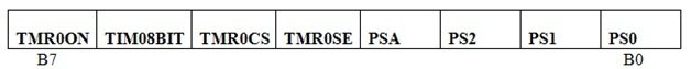
TMR0ON: Timer0 on/off bit
This bit is set to high to enable the Timer0.
- 1 = Enable the Timer0
- 0 = to stop Timer0
T08BIT: 8/16 bit mode selection bit
This bit selects the Timer mode.
- 1 = Timer0 is configured as an 8-bit timer/counter.
- 0 = Timer0 is configured as a 16-bit timer/counter.
TMR0CS: Timer0 Clock Source set
Timer mode is selected by clearing the TMR0CS bit of the Control register.
- 1 = T0 Clk
- 0 = Fosc/4
TMR0SE: Timer0 source Edge select
The rising or falling transition of the incrementing edge for either input source is determined by the TMR0SE bit in the Control register.
- 1 = Increment TMR0 on high to low transition
- 0 = Increment TMR0 on low to high transition
PSA: Pre-scaler Assignment
The pre-scaler is enabled by clearing the PSA bit of the Control register.
- 1 = Pre-scaler not Assigned to TMR0
- 0 = Pre-scaler Assigned to TMR0
PS2, PS2, PS0: Pre-scaler Rate Select bits
There are eight pre-scaler options for the Timer0 module ranging from 1:2 to 1:256. The pre-scaler values are selectable via the PS 2:0 bits of the Control register. In order to have a 1:1 pre-scaler value for the Timer0 module, the pre-scaler must be disabled by setting the PSA bit of the Control register.

Timer0 Interrupt Control Register
| GIE | PEIE | TMR0IE | INTE | IOCIE | TMROIF | INTF | IOCIF |
| B7 | B0 |
TMR0IE: Timer0 Interrupt Enable
This bit is used to enable/disable the Timer0 overflow interrupt.
- 1 = TMR0 Interrupt enabled
- 0 = TMR0 Interrupt disabled
TMROIF: Timer0 Interrupt Flag
This is Timer0 overflow flag bit which is bit is set when TMR0 register overflows. This bit is cleared by the software.
1 = TMR0 has overflowed
0 = TMR0 did not overflowed
TMR0 (Timer0 Register)
This register is divided into registers
- TMR0H
- TMR0L
Both registers are separately accessible thus Timer0 can work in both 8-bit and 16-bit modes. In these registers, pre-calculated value for delay is filled.
Working of PIC microcontroller timers

Timer0 can operate as a timer or as a counter. When the clock source is the instruction cycle clock, it operates as a timer, and when the clock source is the T0CKI pin, it operates as a counter. When the PIC18F452 reads the TMR0L register, the upper half of Timer0 is latched into the TMR0H register. This ensures that the PIC18 always reads a 16-bit value where the upper byte and lower byte belong to the same time.

Circuit Diagram
In this section, we will see an example to generate delay of 1 second using pic microcontroller timers. By using timer0, we will generate a delay and each LED will turn on after every one second and rest of the LEDs will remain off.
For example, this circuit contains 8 LEDs. At the start, LED D1 will glow and rest of the LEDs will remain off. Similarly, after another one second, LED D2 will glow and rest of the LEDs will remain off. This sequential pattern continues, with each LED illuminating one by one after the duration of a single second.

For Programming:
- Firstly through T0CON register, we will select the Pre-scaler, Clock option and Mode of Timer0.
- Then we fill the higher byte of Timer value in TMR0H and then fill lower byte value in TMR0L
- Now set the TMR0ON bit to start the timer. Wait until the TMR0IF flag gets high
- As TMR0IF gets high, we set it to zero and stop the timer by clearing the TMR0ON bit. To start the Timer0 again repeat this process of placing higher byte and lower byte with help of while loop.
MikroC Code
The code for this project is written in the MIKROC compiler and 8Mhz crystal is used in this project. If you do not know how to use MikroC for Pic, you can refer to these tutorials:
- How to Use “MikroC PRO for PIC” to Program PIC Microcontrollers
- Pic microcontroller programming in c using Mikroc Pro for PIC
void main()
{
    // Configure Port B as an output port
    TRISB = 0;

    // Turn on the LED on PORT B pin 0
    LATB = 0x01;

    // Configure Timer0
    T0CON = 0x07;  // Prescaler = 1:256, 16-bit mode, Internal Clock

    while (1)
    {
        // Values calculated for a 1-second delay with a 20MHz crystal
        TMR0H = 0xB3;  // Place the higher byte in TMR0H
        TMR0L = 0xB4;  // Place the lower byte in TMR0L
        T0CON.TMR0ON = 1;  // Turn Timer0 On

        // Wait until TMR0IF gets flagged
        while (INTCON.TMR0IF == 0);

        T0CON.TMR0ON = 0;  // Turn Timer0 Off
        INTCON.TMR0IF = 0;  // Clear Timer0 interrupt flag

        // Circular right shift at PortB to shift the LED
        LATB = (LATB << 1) | (LATB >> 7);
    }
}
MPLAB XC8 Compiler Code
If you do not know how to use MPLAB XC8 compiler, you can follow this guide first:
if you are using MPLAB XC8 compiler instead of mikroC for pic, you can use this code:
#include <xc.h> // Include the XC8 library for PIC18F series

// Interrupt Service Routine (ISR) for Timer0
void __interrupt() Timer0_ISR()
{
    if (TMR0IF)
    {
        // Clear Timer0 interrupt flag
        TMR0IF = 0;

        // Values calculated for 1 second delay with 20MHz crystal
        TMR0H = 0xB3; // Placing the higher byte in TMR0H
        TMR0L = 0xB4; // Placing the lower byte in TMR0L

        // Toggle the LED (Circular right shift at PortB)
        LATB = (LATB << 1) | (LATB >> 7);
    }
}

void main()
{
    // Configure Port B as an output Port.
    TRISB = 0;

    // Turn on LED on PORT B pin 0
    LATB = 0x01;

    // Configure Timer0
    T0CON = 0x87; // Prescaler = 1:256, 16-bit mode, Internal Clock, Timer0 Enabled

    // Enable Timer0 overflow interrupt
    TMR0IE = 1;

    // Enable global interrupts
    GIE = 1;

    while (1)
    {
        // Your main code can continue here without blocking
    }
}
How Does Code Work?
This line of code includes the necessary header file for the XC8 compiler, which provides access to the functions and definitions specific to the PIC18F series microcontrollers.
#include <xc.h> // Include the XC8 library for PIC18F seriesAn Interrupt Service Routine (ISR) for Timer0 is defined in this section. The ISR will be executed whenever the Timer0 interrupt flag (TMR0IF) is set. Inside the ISR, the code clears the Timer0 interrupt flag, loads the TMR0H and TMR0L registers with specific values to create a 1-second delay, and toggles the LED pattern connected to PortB using a circular right shift operation.
void __interrupt() Timer0_ISR()
{
    if (TMR0IF)
    {
        // Clear Timer0 interrupt flag
        TMR0IF = 0;

        // Values calculated for 1 second delay with 20MHz crystal
        TMR0H = 0xB3; // Placing the higher byte in TMR0H
        TMR0L = 0xB4; // Placing the lower byte in TMR0L

        // Toggle the LED (Circular right shift at PortB)
        LATB = (LATB << 1) | (LATB >> 7);
    }
}
In the main() function, the code sets up the necessary configurations. The Port B is configured as an output port using the TRISB register. The LED connected to PORT B pin 0 is turned on by setting the LATB register value to 0x01.
The T0CON register configures the Timer0. We write the value 0x87 to T0CON to set the pre-scaler to 1:256, enable 16-bit mode, use the internal clock, and enable Timer0. We enable the Timer0 overflow interrupt by setting the TMR0IE flag to 1. Finally, we enable global interrupts by setting the GIE flag to 1.
The main loop contains no blocking code and allows the program to perform other tasks while the Timer0 interrupts handle the delay and LED toggling.
void main()
{
    // Configure Port B as an output Port.
    TRISB = 0;

    // Turn on LED on PORT B pin 0
    LATB = 0x01;

    // Configure Timer0
    T0CON = 0x87; // Pre-scaler = 1:256, 16-bit mode, Internal Clock, Timer0 Enabled

    // Enable Timer0 overflow interrupt
    TMR0IE = 1;

    // Enable global interrupts
    GIE = 1;

    while (1)
    {
        // Your main code can continue here without blocking

    }
}
Demonstration
Conclusion:
In this tutorial, we learned how to use PIC18F452’s Timer0 to obtain a delay of approximately 1 second. Moreover, the timer can also be used to find the execution time of a function. Similarly, we can use other timers by carefully considering their datasheets.
Related content:
- How to use pic microcontroller timers as a interrupt
- PWM using Pic Microcontroller with Examples
- UART Communication with Pic Microcontroller( Programming in MPLAB XC8 )
- How to use DAC Module of Pic Microcontroller and Generate waveforms
- PIC Microcontroller ADC – How to Use PIC18F4550 ADC
- PIR sensor interfacing with pic microcontroller
- HC-SR04 Ultrasonic Sensor Interfacing with Pic Microcontroller – Distance Measurement
THANKS SO MUCH
Thanks so much for this hints you have given us. However, please I’m one of your readers, concerns this timer. Apart of this configuration, please could you guide me on how to use only two terminals of the port in such that the first output terminal High (Delay) for about says, 5 sec and off permanently while the other output becomes High permanently after the first terminal goes off. Thanks God bless
How to calculate delay for PIC32MX family controller.