TSOP1738 is an IR receiver with an amplifier that acts as a switch and converter within a circuit. It has one input and output which only acts on the base of the input IR signal. The basic purpose of TSOP1738 is to convert the IR signal to electric signals. Every IR receiver has a special frequency to operate. TSOP1738 operates on 38KHz IR frequency. In case of higher or lower frequency, it may act due to a current leakage or some other errors but it won’t fully operate. It uses silicon-based technology, which works at the microlevel and very sensitive and efficient to its functions. In summary, TSOP may be smaller in size but its usage with microcontroller and microprocessors makes it smart and secure.
TSOP1738 Pinout diagram
TSOP1738 is just an IR receiver which acts as a switch. It has only three pins that connect TSOP with other devices and make it useful for wireless communication.
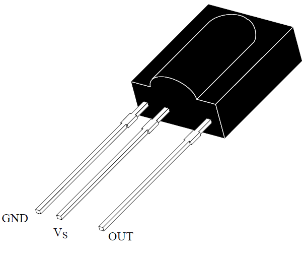
TSOP1738 Pin Configuration
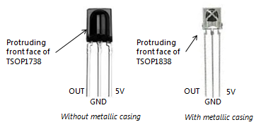
We can find it with a metallic head also. As shown in the figure below:
Pinout Description
GND: The ground pin is only to make common ground with other devices, especially microcontrollers and ICs.
VSS: It is a power input pin for activating the internal decoder and IR receiver. The power should be according to its specification and should be only at power pin. In case of power input on any pin even if its low the IC will start heat up which can be noticed by touching it. In the end, heating will damage the TSOP.
Output: The data will come out in the form of the pulse from the output pin. The output pin can be interfaced with any TTL/CMOS devices with a little resistance. Output data will be in voltage form, from the TSOP.
TSOP1738 IR Receiver Features
- It gives the IR receiver and amplifier within a single package.
- Special frequency level makes it operate with a specific device.
- TSOP1738 has an internal bandpass filter to avoid any ambient light especially sunlight.
- The internal filter gives PCM frequency for analog signals
- It is usable with any kind of TTL/CMOS microcontroller, IC or microprocessors.
- Even there are multiple features in a single package the IC still, has low power consumption and the power consumption only happens when it is operating. At stand by position, the power consumption becomes lower.
- TSOP1738 can transfer 1200bits/s and can receive it at the same speed.
- It is an active low output device.
Specifications
- The operating voltage and current for TSOP is -0.3 to 6.0 V and 5mA current.
- The output voltage and current will always be according to the power input.
- The internal junction temperate range is 100 ⁰C.
- TSOP1738 can operate at -25 to 85 ⁰C but it can also store that temperate.
- Its power consumption is 50mW at a maximum temperature which is 85 ⁰C.
- During soldering the IC always keeps the temperature low than 260 ⁰C near its pins otherwise it will burn with external temperature during soldering.
How does the IR receiver work?
The given image is a general block diagram of the internal components of TSOP1738. The detail of every component is discussed below:

TSOP1738 Block Diagram
AGC
As from the block diagram the internal components can be seen clearly but here the use of each component is a reason. IR receiver can work directly but in TSOP other components makes it smart and secure. The IR is first connected to the AGC (Automatic Gain Control). AGC amplifies the input of different types of input signals from the IR receiver. The AGC then passes the output towards the Bandpass filter.
Band Pass Filter
Bandpass filter has multiple roles in TSOP. It first converts the incoming analog signals to digital output levels which then pass towards the demodulator. The combination of AGC and bandpass also makes it avoid any ambient light especially the sunlight because it is common and can be found anywhere easily. The device may have internal sunlight protection but still, the company recommends it to use at a shorter distance. The change in weather may sometimes affect the sunlight which can affect the transmission with TSOP. The bandpass filter also makes the IC operate only at a special frequency which is 38KHz.
Demodulator
The demodulator is connected to the NPN transistor from one end and to Band Pass Filter from the other end. The output data from the bandpass filter will be entered in the demodulator which will drive the NPN transistor using low input signals. NPN transistor is directly connected to the power and output from the collector and with the ground from the emitter side. Every low signal will turn off the NPN transistor and power will be pass towards the output pin.
Control Circuit
The control circuit act as a switch for demodulator and band filter. It generates the output signal whenever the bandpass filter generates the output, the control circuit generates the output signal which tells the demodulator and AGC about completion of filtration.
TSOP1738 IR Receiver Applications
- TSOP1738 may be smaller in size but most of the modern products connect with TSOP1738 internally. Like TV, AC, Doors, etc.
- Security systems like object detection use it with the IR transmitter.
- TSOP1738 use in Line following robots to achieve its goal.
- Hear Beat sensor can be built by using TSOP1738.
- Most of the modern security systems in IoT comes with TSOP1738 with different kinds of applications.
- It is one of the best receivers for a small distance communication but it is only for one-way communication.
TSOP1738 Example Circuits
There are a bunch of TSOP1738 applications but every application uses the same method and circuit. Especially at the commercial level, the TSOP1738 use to make wireless communication to avoid any kind of interaction between humans and machines due to many issues, mostly safety.
Controlling LED with IR remote
In this example, TSOP will be used as a remote tester. In most of the local shops, they have a remote tester that has TSOP1738 within itself, which helps to read the incoming signal.

The basic purpose of this device is to view the incoming signal from the remote. The signal coming from remote is unable to see with the naked eye. The following circuit helps the vendors to view the remote signals in the form of light.
TSOP1738 Example
In this circuit, TSOP1738 operates an LED by using transistors and some resistors. The output of the TSOP connects with the base of the NPN transistor and the transistor controls the LED. Whenever the remote button will press in front of the TSOP1738 the LED will start blinking. The blink of LED will be according to the incoming signal and can be viewed by the human eye easily.
Controlling LED with Arduino
In this example, we learn to control the LED with Arduino. This diagram shows an IR receiver interfacing with Arduino.

For working and code check this complete article and video:
Projects Examples
These are the projects based on TSOO1738.
- Bidirectional Rotation of an Induction Motor with a Remote Control Device
- IR remote controlled home automation system using Arduino
- Bidirectional Rotation of an Induction Motor with a Remote Control Device
Security issues with TSOP1738
The decoding speed of TSOP makes it smarter. In most of the devices, TSOP1738 connects with microcontrollers. In a microcontroller, there are a bunch of methods by which the microcontroller will act on the incoming signal. The receiver can transfer the data up to 1200bit/sec. In the controller, the incoming data can be defined for different events. The larger number of data is hard for anyone to guess and there is no way to bypass the TSOP directly.
Many generate able data may help to make the device secure but there’s a flaw in this system too. Whenever the transmitter sends the data, it doesn’t have any restrictions for the receiver end. Any device with TSOP1738 can receive the data. TSOP1738 doesn’t have any smart detection method of neglecting the incoming signal. The only basic function of TSOP is to generate the incoming IR signal to the electrical signals. This is the reason every remote can be reverse-engineered by using Microcontroller with TSOP1738. This issue doesn’t affect much because IR transmission only uses in short transmission devices.
2D Diagram

Other Wireless Modules:
Some discrepancy in your drawings. 1st one show G/V/O second one, with the metalic shows O/G/V. So that’s not even accurate if you have the device backwards.
Hi, thanks for pointing out a mistake. We will update the correct one.
For the remote tester. It’s a bit over complicated. I’ve found these IR receivers can drive an LED on their own. Use an LED and 1k resistor between battery positive and receiver output pin, when a signal is received the output pin pulls low and the LED lights up. I’ve got one I’ve been using like this to test old remotes for years without issues.
How to implement 3 pin receiver block diagram using 2 pin photo diode to use higher carrier frequency and so higher baud rate? Especially Demodulator.