In this tutorial, we will delve into the world of AC circuit analysis using PSpice. AC circuits are circuits that utilize alternating current as the power source, as opposed to direct current. To begin, we will provide a brief introduction to AC currents and their characteristics. We will then guide you through the process of designing a simple AC circuit in PSpice, analyzing the results along the way. By the end of this tutorial, you will have gained valuable insights into AC circuits and be equipped to tackle more complex analyses in the future. So let’s get started on our journey into the world of AC circuit analysis in PSpice!
Introduction to AC circuits analysis
A simple AC circuit is a circuit in which an alternating current source is used. In an AC circuit the source oscillates continuously as in the case of a sine wave. A simple AC voltage source is shown in the figure below,

Figure 1: Voltage source
On a complete cycle of an AC voltage source, there are two half cycles: one is the positive half cycle and the other is the negative half cycle. The polarities in both half cycles will be different from each other. The same Ohm’s Law, as discussed in the previous tutorial, applies to AC voltage as well. If a resistor is present, it will change the value of the current accordingly while keeping the voltage constant.
Example of AC circuits Analysis in PSpice
Let’s design a simple AC circuit i.e. a circuit with AC source as a supply. Open the PSPICE design manager on your PC by typing design manager in the search bar. From the design manager click on the run schematic button to open a new blank schematic as shown in the figure below,

Figure 2: Open new schematic
After opening the new schematic before jumping into designing first save the schematic by clicking on the file button at the top left corner and then selecting save as so that we can access it anytime in the future. Refer to the figure below,

Figure 3: Saving schematic
Click on the get new part icon at the top bar of the schematic window in order to search for the components that are needed for circuit designing.
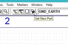
Figure 4: Get a new part
In the get new part window, type ‘r’ it will display a list of resistors available in PSPICE. From that list select a simple resistor as shown in the figure below,

Figure 5: Inserting a resistor
Again open the get new part window and in the part name block type ‘C’, select the capacitor from the list given, and then click on place & close as shown in the figure below

Figure 6: Capacitor placement
Again open the get new part window and in the pat name block type Vac, select the supply from the list given and then click on place & close as shown in the figure below
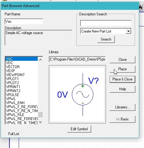
Figure 7: Place input sin
The next step is to place a ground. Repeat the same process and in the part name, type “Gnd” and select the ground. Then, click on “Place & Close” as shown in the figure below.
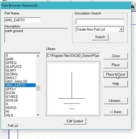
Figure 8: Placing ground
The placed components in the schematic window are shown in the figure below,

Figure 9: Placed components
Click on the draw wire icon at the top bar of the schematic window in order to connect the already placed components for circuit designing.

Figure 10: Drawing wire
Connect all the components to complete the circuit diagram as shown in the figure below,

Figure 11: Complete circuit diagram
Next, you need to set the attributes of the input AC supply. Double-click on the AC supply that you connected in the circuit previously, and set the magnitude of the supply voltage to 10V and the DC voltage to 0, as shown in the figure below:

Figure 12: AC attributes
Set the value of the capacitor according to the requirement of your circuit by double-clicking on the component and changing the value to 3u. Then, click “Save Attr” as I have set the value here to 3uF, as shown in the figure below:

Figure 13: Capacitor values
On the top of the schematic window, click on the Voltage/Level Marker button as shown in the figure below:

Figure 14: Voltage marker
Place it at the capacitor node as shown in the figure below:
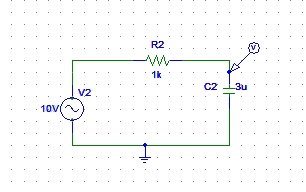
Figure 15: Placed voltage marker
Next step is to adjust the properties of the simulations to produce the graph of the voltage at the marker. Click on analysis and then click on Setup, as shown in the figure below:
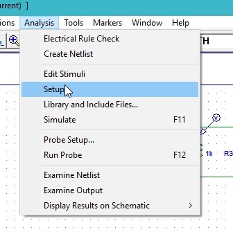
Figure 16: Simulation setup
A widow will appear, click on the AC Sweep block on the window, and adjust the properties of the window according to your requirement. Refer to the figure below:
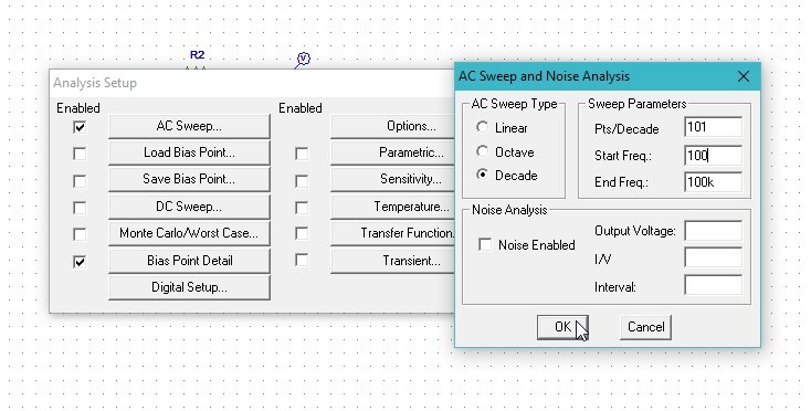
Figure 17: AC sweep properties
Change the start and end frequency in the property window according to the portion of the graph you want to see. If you are interested in checking the voltage on a specific wire instead of checking it at a node, double click on the wire and in the window that appears, type the name of the wire you want to label it with, as shown in the figure below.

Figure 18: Labeling the wire
Now comes the simulation part. Click on “Analysis” at the top bar of the schematic window, and then click on “Simulate” as shown in the figure below:

Figure 19: Simulation
The output voltage at the capacitor node is displayed in the figure below:
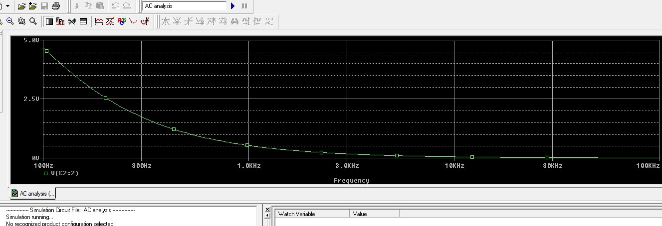
Figure 20: Output voltage at the capacitor node
The decreasing sweep at the capacitor node here implies the discharging of the capacitor. As in case of an AC circuit the input signal source consists of two half part or cycles. One is the positive half cycle of the AC signal and the other is the negative half cycle. During the positive half cycle, the direction of the current i.e. the polarity of the voltage will be in accordance with polarity of the capacitor and the capacitor will start charging during the positive half cycle, whereas during the negative half cycle due do the inversion the polarity of the voltage source, the polarity of the capacitor will be opposite to that of the source, hence taking into account the charging and discharging concept of a capacitor, the capacitor will start discharging the stored charge ( during the positive half cycle) to the circuit. The exponentially decreasing curve in the above graph implies the discharging phenomenon of the capacitor.
Connect another voltage marker at the input of the AC source to see the AC sweep of the source along with that of the capacitor, as shown in the figure below:

Figure 21: Marker at input
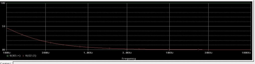
The output after connecting the voltage marker to the input is shown in the figure below:
View full size
Figure 22: Output displayed along with input
- The green line at the top represents the input AC sweep of the AC source connect. The straight line represents that the input source is constant (neither increasing nor decreasing with time) unlike that of the capacitor voltage.
Exercise
- Do the AC analysis of the circuit containing an inductor at the place of a capacitor.
Conclusion
In this tutorial, we learned about AC circuit analysis using PSPICE. We started with a brief introduction to AC circuits and how they differ from DC circuits. Then, we went through the step-by-step process of designing a simple AC circuit using PSPICE.
We learned how to place components, draw wires to connect them, and set the attributes of the AC supply and capacitor in the circuit. We also learned how to place voltage markers and set up the simulation properties to analyze the circuit.
By simulating the circuit, we were able to observe the voltage behavior at different nodes in the circuit. We saw how the capacitor charges and discharges during the positive and negative half cycles of the AC signal.
In the exercise, we were encouraged to perform AC analysis on a circuit with an inductor instead of a capacitor, which would give us insights into the behavior of inductors in AC circuits.
Overall, this tutorial provided a practical understanding of AC circuit analysis using PSPICE, and by applying these concepts, we can analyze more complex AC circuits in our future projects.