In this tutorial, we will explain how to use PSPICE to design a circuit schematic for the first time. We will explain the use of PSPICE schematics, including how to create a project, how to use basic components that are needed to design a very basic electrical circuit, and how to add libraries to the components part. An explanation of the basic components and their uses in circuit development is given. In the last tutorial, we saw how to download and install PSPICE software.
Introduction to PSpice Schematic
Cadence Design Systems developed the PSpice software. It is a powerful software with versatile schematic capture and simulation tools. This is the most commonly used in the field of electronics and electrical engineering. PSPICE is short for “Programmable Simulation Software with Integrated Circuit Emphasis”, as it provides circuit creation, analysis, and simulation for engineers and researchers. PSPICE provides a user-friendly interface for creating schematic diagrams that represent the circuit’s components and connections, enabling accurate simulation and analysis to predict circuit behavior before physical implementation. We will learn how to work with PSICE software and design a schematic in the next section.
Working with PSpice Schematics
Let’s see If we want to draw a simple circuit and test it virtually, the first step is to open the schematic. Open the search bar on the system or press the search key on the keyboard and type Capture, as shown in the figure below.

Creating Project
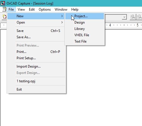
Click on the option as shown in the figure above; this will open the window for drawing the schematics of the required circuit. We have to create a project first in order to draw the circuit; for that purpose, click on the file at the top of the schematic window. A drop-down menu will appear. From that drop-down menu, select new, and from the sub-dropdown menu, select project, as shown in the figure below.
This will open a window asking to set the name and destination folder of the project we are going to create, as shown in the figure below.

First, we write the name of the project to assign to the project we want to create in the block labeled Name, as shown in the figure above. Check the type from the list, as I have checked the schematic in the above figure.
In the location labeled block, we have to type the address of the folder in which we want to save the project. For typing the address of the folder, a shortcut is available to browse the desired destination folder. When we click the browse button, it will ask us to select the destination folder.
Schematic
Now, we will select a folder of our choice and click OK. This will create a folder with the entered project name. After creating the folder, the PSPICE window will open the schematic, as shown in the figure below.
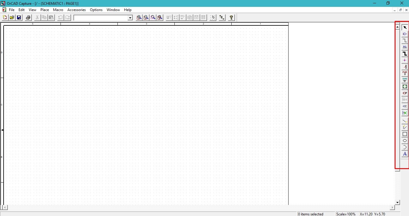
The highlighted portion in the above figure shows the components that we will be using in the later tutorials, where we will be working with extensive circuits and checking their response under different circumstances. I will list the use of all these components shortly. Let’s now start with the first component, named place part, as shown in the figure below.

This option will allow us to place very basic components regarding the circuit’s design, i.e., resistors, capacitors, or inductors. The installed version of PSpice includes only some basic components of electronics, like resistors, power supplies, and ground. But if we want to work on an extensive scale, which includes extensive circuitry and some high-power diodes, we must include the required libraries for that purpose.
Add Library
But this is not a big issue; the downloaded files that we got in the previous tutorial already contain almost every library included in the place part block. All we have to do is include them. Let us complete this task first. Click on the place block option and then click on include library, as shown in the figure below.

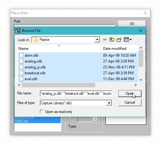
After clicking on add library, it asks us to specify the folder where the libraries are stored. Select the folder as shown in the figure below, and click OK.
It will include all the libraries in the place part block. We can select almost all the available components from here, as we will do in our upcoming tutorials. On the search bar, in the place block component, write Vac, which is the short form of AC voltage source.
Component Placement
It will allow us to place the AC source on our schematic, as shown in the figure below. Place the AC voltage power supply on the schematic, and let’s proceed with the design further.

Similarly, if we want to place a resistor, for instance, simply type resistor in the search bar. If we want to place a component on the schematic, we just have to know the name of that component and nothing else. Simply write the name of the component and select it from the list thus obtained. For the case of selecting a resistor, refer to the figure below. Place the resistor on the schematic too, along with the supply already placed.

We can also place a capacitor on an inductor by searching for it in the place part block and selecting the specified component from the list. Now let’s move to the second icon at the right of the schematic or PSPICE screen, which is place wire. As the name suggests, it is used to place a wire between two components. Referring to the figure below.

Placing Wires
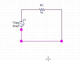
Selecting this icon will help us connect the supply and resistor we placed previously, as shown in the figure below.
While talking about the icons at the right of the PSPICE window, let’s discuss the most common icons and leave the further details for upcoming tutorials. The basic electrical components when talking about the circuit design are the supply and the ground. We have already talked about placing the supply on the schematic, and now we will discuss the ground. From the icons at the right, select the ground as shown in the figure below.

We can also place text blocks on the schematic for commenting or labeling purposes, from the icons present at the bottom, as shown in the figure below,

Above the text-placing icon, some other icons are also present that are used to place shapes, i.e., lines, an eclipse, a circle, or an arc, on our schematic. These shapes and text blocks have nothing to do with the circuitry of our design; they are just for labeling and commenting purposes and also for making the circuit more visually representable and effective. Refer to the figure below, which shows the place-shaped icons.

Edit Part Block
We can also change the value or style of already-placed components by clicking on them. For example, in our case, by double-clicking on one of the already placed components, i.e., the resistor, a box will appear allowing us to edit the details of the component, as shown in the figure below.
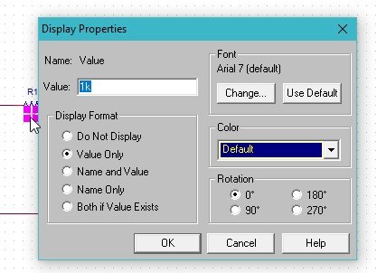
We can change the value of the block, resistance in our case, to our desired values, let’s say 200 ohms, as shown in the figure below, and click on the change button.

We can also change the color of the part or component in order to increase its visual effectiveness by selecting the desired color from the range as shown in the figure below.

Also, we can format the display of the component according to our choice from the list highlighted in the figure below.

Conclusion
In conclusion, this tutorial provides an in-depth overview of the PSpice software and how to build a schematic. It also covers a step-by-step example with an explanation. This helps us better understand the concept of PSpice software. You can utilize this tutorial to build more advanced circuits using the PSpice software. Hopefully, this tutorial gets you started with building schematics using PSpice.
You may also like to read
- ESP32 HTTPS Requests using Arduino IDE
- Difference Between Raspberry Pi and Arduino
- TEENSY 3.2 Development Board – Getting Started Tutorial
- Ethernet based Home Automation using Arduino – IOT
- IoT Sound Pollution Monitoring System using ESP32 – Decibel Meter
This concludes today’s article. If you face any issues or difficulties, let us know in the comment section below.