TEENSY Development Boards are quite famous for small projects, either for a hobbyist or designing small robots or entertainment stages. One of such boards is a TEENSY 3.2 Development Board made by PJRC. It is a bread-board compatible, USB development board of K20 Sub-Family with a 32-bit ARM Cortex-M4 microcontroller unit to implement different prototypes and designs. It has an excellent Central Processing speed of 72 MHz and I2S for a fine quality audio interfacing and a touch sensor interface.
This tutorial is an introduction to the TEENSY 3.2 Development Board. All the features, specifications, pin configuration, GPIO pins and peripherals, and applications will be discussed here.
Recommended Components
The following parts are used in this article, along with a generic electronics kit that is handy for building and testing the circuit.
| Component | How it’s used | Buy on Amazon |
|---|---|---|
| Teensy 3.2 development board | The Teensy 3.2 ARM Cortex-M4 board this article covers. | Check Price |
| Electronic component assortment kit (1390 pcs) | A handy assortment of resistors, capacitors, LEDs, diodes and transistors for building circuits. | Check Price |
| Digital multimeter (AstroAI) | Measures voltage, current, resistance and checks continuity while you build and debug. | Check Price |
| Breadboard | Solderless base for prototyping the circuit. | Check Price |
| Jumper Wires | Make the connections on the breadboard. | Check Price |
As an Amazon Associate we earn from qualifying purchases. Prices and availability are accurate as of the date/time indicated and are subject to change.
TEENSY 3.2 Introduction
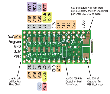
TEENSY 3.2 is an upgraded version of TEENSY 3.1 with 2X Flash memory. Though small but outstanding, TEENSY 3.2 comes with the MK20DX256VLH7 microcontroller unit. It has 34 GPIO pins and Communication ports for serial data transmission. But we use only solderless pinout, 24 GPIO pins are accessible. The remaining pins are accessible through the soldering connection shown at the backside of the TEENSY 3.2 development board
The board is energy-efficient but has a wide range of input power supply. TEENSY 3.2 is very simple and easy to use.
TEENSY 3.2 Pinout
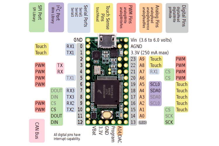
The following diagram shows the pinout of the TEENSY 3.2 Development Board from the front end:
The following figure shows the pinout diagram of TEENSY 3.2 from the back side:
Pin Configuration
Let us discuss the pinout of the TEENSY 3.2 Development Board. The pin configuration detail in tabular is mentioned below:
| Type | Pin Number | Function |
|---|---|---|
| Power | VIN3.3 Volts(250 mA)GNDAnalog GND | 1. Power Supply from USB or any external source pin 2. Operational Output Voltage pin 3. Ground for ADC/DAC pin 4. Ground Pin |
| Analog Pins ( ADC) | A0-A20 | 21 Analog channels with up to 16-bits programmable resolution. But the default resolution is 10-bit. But due to noise, only up to 13-bit resolution is useable. |
| I/O Pins | D0-D33 | Teensy 3.2 General Purpose I/O pins are 5V tolerant and can accept voltage in the range of 0-5V. All GPIO pins have internal PULL-UP and PULL-DOWN resistors. |
| External Interrupts | D0-D33 | All 34 GPIO pins can detect external changes. Hence, can be used as interrupt pins |
| PWM | D3-D6, D9-D10, D20-D23, D25, D32 | 12 Pulse-width Modulation pins |
| UART– Serial Communication | TX1 – D1, RX1 – D0, TX2 – D10, RX2 -D9, TX3 -D8, RX3 – D7 | 3 UART bases serial communication ports |
| SPI | DIN, DOUT, SCK, CS | Serial Peripheral Interface pins ( D7 -D12) |
| CAN | TX – D3, RX – D4 | Controller Area Network Bus pins |
| I2C | SCL0 – D19, SDA0 -D18 SCL1 – D29, SDA1 – D30 | Inter-Integrated Circuit Serial Data and Clock pins |
| Built-in LED | D13 | LED for Indication |
| TSI | D0-D1, D15-D19, D22-D23 | Touch Sensing Interface pins |
- Power pins: The board has three different pins to supply the power depending on our choice. One is through an external power supply with the mentioned voltage range in the table. The second is through USB Connector, which typically provides 5 Volts, and the third is through supplying a 3.3 Volts pin, which is usually avoided for the sake of MCU.
- Serial Comm Ports: The board has all the advanced serial data transmission ports(USART, I2C, CAN, SPI) for bi-directional, synchronous, bitwise serial communication between the chip and the peripherals.
- TSI: Touch Sensing Interface is a human-machine interface to detect input capacitive touch.
Features and Specifications
| Features and Peripherals | Availability |
|---|---|
| MCU | MK20DX256VLH7 |
| Number of Analog Comparators | 3 |
| SRAM | 64 KiloBytes |
| Serial wire Debug | No |
| Flash Memory | 256 KiloBytes |
| CPU speed | 72 MHz |
| USB Connector | Micro |
| ADC | 2 |
| Recommended Input Voltage | 3.6-6.0 Volts |
| EEPROM | 2 KiloBytes |
| USB module | Yes |
| I2C | 1 |
| SPI | 1 |
| Operational Temperature | -400C – 1050C |
| Number of Timers | 8 |
| Operational Voltage | 1.71V – 3.6V |
| USART module | 3 |
| Internal Oscillator | 3-32 MHz |
| JTAG debug Interface | 1 |
| Source/Sink Current | 10 mA |
- CPU Speed: 72 MHz
- Flash Memory: 256 Kilobytes
- EEPROM: 2 Kilobytes
- StaticRAM: 64 KiloBytes
- Pulse-width Modulation pins: 12 pins
- Analog Pins: 21 pins
- Digital Pins: 34 pins
TEENSY 3.2 Peripherals Specification
Some of the attributes of the extra features are laid out below:
- Provided with a 12-bit DAC to produce accurate voltage levels
- 16 direct memory access controllers for immediate access for 64 request sources
- A cyclic redundancy check for fast error monitoring
- A 32 kHz Oscillator for Real-Time Clock
- It comes with 8 different timers to give different delays
- An integrated I2S (Inter-IC-Sound) interface for connecting audio devices to the MCU for pulse code modulated data transmission
- It contains a watchdog and JTAG(Joint Test Action Group) interface
- A human-machine interface to provide easiness and authentic accessibility
- Each microcontroller unit chip has a distinct identification number for security purposes
How to Program TEENSY 3.2 Development Board
TEENSY Development Board can be programmed through
- Visual Micro
- Arduino Software with Teensyduino add-on
- PlatformIO
- Command-Line with Makefile
TEENSY Boards are very compatible with almost all of the Arduino libraries. Arduino has introduced an add-on for TEENSY known as Teensyduino. Check this tutorial for Arduino IDE getting started tutorials
If you know Arduino programming, you can easily use this development board. Because all libraries of Arduino IDE are compatible with the Teensy 3.2 board. We just need to install the library of the TEENSY 2.3 development Board in Arduino IDE.
Add Teensyduino Add-on to Arduino IDE
To program, TEENSY 3.2 development board with Ardino IDE, first download and install the ad-on from this link:
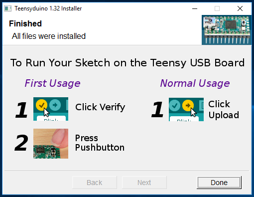
Add-on is available for Linux, Windows, and MAC OS. Download the Teensyduino according to your operating system and install it. Teensyduino installer adds all the required files for Teensy development board to use with Arduino IDE.
Once the addon installed successfully, you will see the screen like this. Click on the done button.
Open your Arduino IDE and select Teensy in the Tools > Boards menu.
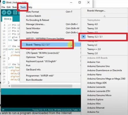
Now open the LED Blinking example. To upload a TEENSY’S MCU program, Select the Board name: TEENSY 3.2 from the “Tools ” and communication port through which the code/sketch will be burnt on the Microcontroller Unit. More or Less, all programs created are compatible with TEENSY too. But to visually see the compatibility, upload the Blink Sketch and observe the inbuilt LED, i.e., D13 on the board.
Applications
- Robotics
- Home automation systems
- LED walls
- Low-power embedded systems
- Entertainment platforms
Datasheet
The link to the datasheet is given below to see further details and specifications of the TEENSY 3.2 Development Board.
Other Development Boards:
- STM32F103C8T6 Blue Pill
- Raspberry Pi Pico
- TEENSY 3.6 development board
- STM32 Nucleo F401RE Development Board
- Arduino MKR1000 WiFi Board
- STM32F4 Discovery Board
- Raspberry Pi 4 Development Board
- LPC2148 Microcontroller
- ESP32
- ESP8266
- Tiva LaunchPad
- MSP430G2 Development Board
- BeagleBone Black
- Arduino Mini
- Arduino Nano