In this tutorial, we will build a data logger using Raspberry Pi Pico and MicroPython. We will log temperature and humidity readings acquired from a DHT22 sensor to a microSD card. The program creates a .txt file on the microSD card and appends fresh temperature and humidity readings every 30 seconds. This project demonstrates a complete, practical workflow: reading sensor data, formatting it as text, and writing it to persistent storage that survives power cycles.
Data logging is an essential technique in embedded systems. Instead of simply displaying readings on a screen, logging stores values over time so you can analyze trends, detect anomalies, or generate reports after a monitoring session ends. A microSD card is an ideal storage medium for this purpose: it is low cost, removable, and can hold years of sensor data even at high sampling rates.
For a getting-started guide to microSD cards with Raspberry Pi Pico, read: MicroPython: Micro SD Card Interfacing with Raspberry Pi Pico using MicroSD Module
This article is organized into the following sections:
- Introduction to the DHT22 sensor and its connection with Raspberry Pi Pico and the microSD card module
- Formatting the microSD card
- DHT22 data logging to microSD card (installing libraries, MicroPython code, and demonstration)
- CSV logging for spreadsheet compatibility
- Troubleshooting common issues
Prerequisites
Before starting this project, make sure you have MicroPython installed on your Raspberry Pi Pico and a working IDE for writing and uploading code. We will use Thonny IDE throughout this guide. If you have not set up your Pico yet, follow one of these guides first:
- Getting Started with Raspberry Pi Pico using Thonny IDE
- Getting Started with Raspberry Pi Pico using uPyCraft IDE
You will need the following components:
- Raspberry Pi Pico board
- MicroSD card (up to 32GB, formatted as FAT32)
- MicroSD card module
- DHT22 sensor
- 10k ohm resistor (if using bare DHT22 sensor; not needed for module)
- Breadboard
- Connecting wires
DHT22 Introduction
The DHT22 (also sold as AM2302) is a low-cost digital sensor that measures both relative humidity and ambient temperature. It communicates over a single-wire protocol and outputs a calibrated digital signal, so no analog-to-digital conversion is needed on the microcontroller side. Compared to the DHT11, the DHT22 offers higher measurement accuracy (±0.5°C for temperature, ±2–5% for humidity) and a wider operating range: −40°C to +80°C for temperature and 0–100% RH for humidity.
Internally, the DHT22 contains a resistive humidity sensor element and a thermistor. A small onboard chip conditions and digitizes both signals, then transmits them as a 40-bit serial packet when the host microcontroller sends a start pulse. The sensor is factory-calibrated, so no user calibration is required. MicroPython includes a built-in dht module that handles all the low-level timing automatically, making it straightforward to obtain readings with just a few lines of code.
DHT22 Pinout
The DHT22 sensor has four pins. When using the bare sensor (not the breakout module), you must add a 10k ohm pull-up resistor between the VCC pin and the data pin. DHT22 breakout modules have this resistor built in, so only three pins are exposed.
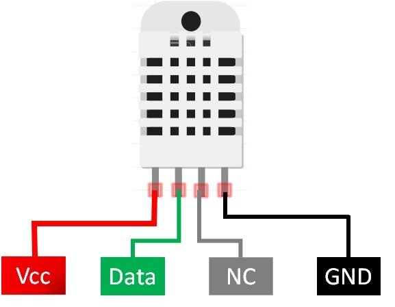
The table below describes the DHT22 pins and how they connect to Raspberry Pi Pico. Pin numbering starts from left to right when facing the sensor’s front (grid side).
| DHT22 Pin | Description | Raspberry Pi Pico |
|---|---|---|
| 1 (VCC) | Power supply (3.3V–5V) | 5V (VBUS) |
| 2 (Data) | Serial data output; requires 10k pull-up resistor | GP2 (with 10k to VCC if bare sensor) |
| 3 (NC) | Not connected | — |
| 4 (GND) | Ground | GND |
Recommended Reading: DHT11 DHT22 with Raspberry Pi Pico using MicroPython
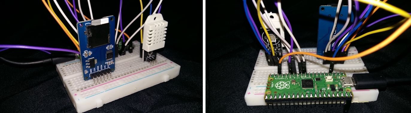
Interfacing Raspberry Pi Pico with DHT22 and MicroSD Card Module
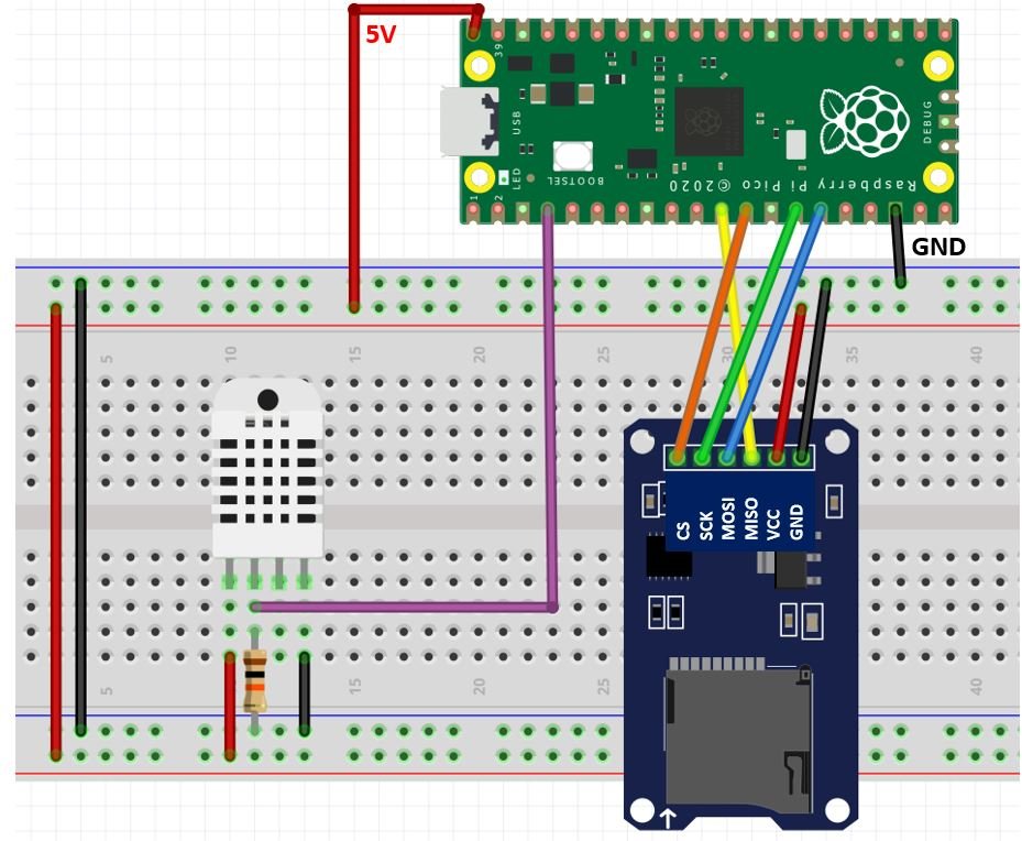
This section explains how to wire Raspberry Pi Pico to both the DHT22 sensor and the microSD card module simultaneously.
The DHT22 sensor’s VCC pin connects to the Pico’s 5V (VBUS) pin. The data pin connects to GP2. If you are using a bare DHT22 (not a module), place a 10k ohm resistor between VCC and the data pin. This pull-up resistor ensures the data line stays at a defined logic high level when the bus is idle — without it, communication will be unreliable or fail entirely. The fourth pin (NC) is left unconnected.
The microSD card module also draws power from the Pico’s 5V pin and shares a common GND. Communication between the Pico and the module uses the SPI bus. The four SPI data lines (MISO, MOSI, SCK, CS) connect to dedicated GPIO pins on SPI peripheral 1. All three GND connections — from the Pico, the DHT22, and the microSD module — must share a common ground.
Raspberry Pi Pico SPI Pins
Raspberry Pi Pico provides two hardware SPI peripherals (SPI0 and SPI1), each of which can be routed to several different GPIO pins. In this project we use SPI1. The table below shows all available SPI pin options; you can use any valid combination for your chosen peripheral, provided you configure the software accordingly.
| SPI Signal | Available GPIO Pins |
| SPI0_RX (MISO) | GP0 / GP4 / GP16 |
| SPI0_TX (MOSI) | GP3 / GP7 / GP19 |
| SPI0_SCK | GP2 / GP6 / GP18 |
| SPI0_CSn | GP1 / GP5 / GP17 |
| SPI1_RX (MISO) | GP8 / GP12 |
| SPI1_TX (MOSI) | GP11 / GP15 |
| SPI1_SCK | GP10 / GP14 |
| SPI1_CSn | GP9 / GP13 |

Schematic Diagram
The tables below summarize all wiring connections for this project. Use these as your reference when assembling the circuit on a breadboard.
| MicroSD Card Module Pin | Raspberry Pi Pico Pin |
|---|---|
| GND | GND |
| VCC | 5V (VBUS) |
| CS | GP9 (SPI1_CSn) |
| MOSI | GP11 (SPI1_TX) |
| SCK | GP10 (SPI1_SCK) |
| MISO | GP8 (SPI1_RX) |
| DHT22 Sensor Pin | Raspberry Pi Pico Pin |
|---|---|
| 1 (VCC) | 5V (VBUS) |
| 2 (Data) | GP2 (+ 10k pull-up if bare sensor) |
| 3 (NC) | — |
| 4 (GND) | GND |
Formatting the MicroSD Card
MicroPython’s uos.VfsFat() function only supports FAT32 (and FAT16 for very small cards). Cards formatted as exFAT or NTFS will not mount correctly. Use a card no larger than 32GB, since most cards in that range ship pre-formatted as FAT32. If your card is formatted differently, follow the steps below to reformat it on Windows.
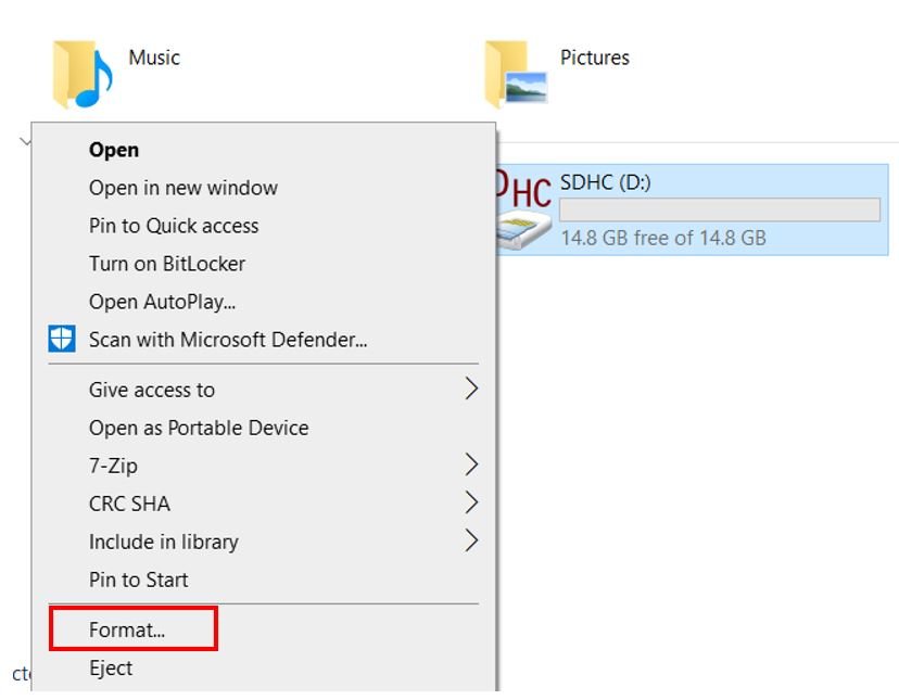
- Insert your microSD card into your computer. Open File Explorer, right-click the drive, and select Format.
- In the Format window, set File System to FAT32 and click Start.

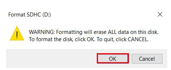
- A warning will appear stating that all existing data will be erased. Click OK to proceed.
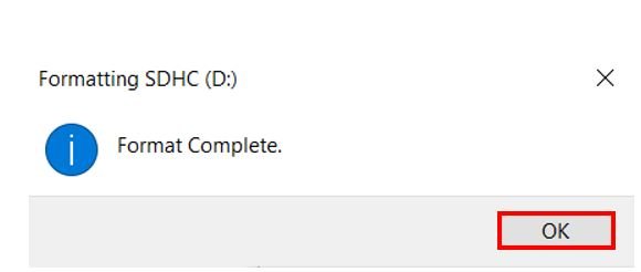
- After a few seconds the format will complete. Click OK. Your card is ready.
On macOS, open Disk Utility, select the card, click Erase, choose MS-DOS (FAT) as the format and Master Boot Record as the scheme, then click Erase.
Installing the SD Card Library
MicroPython does not include an SD card driver by default, so we need to install sdcard.py from the official MicroPython repository. This driver handles all low-level SPI communication with the card, including sending initialization commands, negotiating card version, reading the Card Specific Data (CSD) register to determine capacity, and performing block-level read/write operations that the FAT filesystem layer can use.
Open a new file in Thonny, paste the library code from the GitHub link, and save it to Raspberry Pi Pico as sdcard.py inside the lib folder (create the folder if it does not exist).
sdcard.py
"""
MicroPython driver for SD cards using SPI bus.

Requires an SPI bus and a CS pin.  Provides readblocks and writeblocks
methods so the device can be mounted as a filesystem.

Example usage on pyboard:

    import pyb, sdcard, os
    sd = sdcard.SDCard(pyb.SPI(1), pyb.Pin.board.X5)
    pyb.mount(sd, '/sd2')
    os.listdir('/')

Example usage on ESP8266:

    import machine, sdcard, os
    sd = sdcard.SDCard(machine.SPI(1), machine.Pin(15))
    os.mount(sd, '/sd')
    os.listdir('/')

"""

from micropython import const
import time


_CMD_TIMEOUT = const(100)

_R1_IDLE_STATE = const(1 << 0)
# R1_ERASE_RESET = const(1 << 1)
_R1_ILLEGAL_COMMAND = const(1 << 2)
# R1_COM_CRC_ERROR = const(1 << 3)
# R1_ERASE_SEQUENCE_ERROR = const(1 << 4)
# R1_ADDRESS_ERROR = const(1 << 5)
# R1_PARAMETER_ERROR = const(1 << 6)
_TOKEN_CMD25 = const(0xFC)
_TOKEN_STOP_TRAN = const(0xFD)
_TOKEN_DATA = const(0xFE)


class SDCard:
    def __init__(self, spi, cs, baudrate=1320000):
        self.spi = spi
        self.cs = cs

        self.cmdbuf = bytearray(6)
        self.dummybuf = bytearray(512)
        self.tokenbuf = bytearray(1)
        for i in range(512):
            self.dummybuf[i] = 0xFF
        self.dummybuf_memoryview = memoryview(self.dummybuf)

        # initialise the card
        self.init_card(baudrate)

    def init_spi(self, baudrate):
        try:
            master = self.spi.MASTER
        except AttributeError:
            # on ESP8266
            self.spi.init(baudrate=baudrate, phase=0, polarity=0)
        else:
            # on pyboard
            self.spi.init(master, baudrate=baudrate, phase=0, polarity=0)

    def init_card(self, baudrate):

        # init CS pin
        self.cs.init(self.cs.OUT, value=1)

        # init SPI bus; use low data rate for initialisation
        self.init_spi(100000)

        # clock card at least 100 cycles with cs high
        for i in range(16):
            self.spi.write(b"\xff")

        # CMD0: init card; should return _R1_IDLE_STATE (allow 5 attempts)
        for _ in range(5):
            if self.cmd(0, 0, 0x95) == _R1_IDLE_STATE:
                break
        else:
            raise OSError("no SD card")

        # CMD8: determine card version
        r = self.cmd(8, 0x01AA, 0x87, 4)
        if r == _R1_IDLE_STATE:
            self.init_card_v2()
        elif r == (_R1_IDLE_STATE | _R1_ILLEGAL_COMMAND):
            self.init_card_v1()
        else:
            raise OSError("couldn't determine SD card version")

        # get the number of sectors
        # CMD9: response R2 (R1 byte + 16-byte block read)
        if self.cmd(9, 0, 0, 0, False) != 0:
            raise OSError("no response from SD card")
        csd = bytearray(16)
        self.readinto(csd)
        if csd[0] & 0xC0 == 0x40:  # CSD version 2.0
            self.sectors = ((csd[8] << 8 | csd[9]) + 1) * 1024
        elif csd[0] & 0xC0 == 0x00:  # CSD version 1.0 (old, <=2GB)
            c_size = csd[6] & 0b11 | csd[7] << 2 | (csd[8] & 0b11000000) << 4
            c_size_mult = ((csd[9] & 0b11) << 1) | csd[10] >> 7
            self.sectors = (c_size + 1) * (2 ** (c_size_mult + 2))
        else:
            raise OSError("SD card CSD format not supported")

        # CMD16: set block length to 512 bytes
        if self.cmd(16, 512, 0) != 0:
            raise OSError("can't set 512 block size")

        # set to high data rate now that it's initialised
        self.init_spi(baudrate)

    def init_card_v1(self):
        for i in range(_CMD_TIMEOUT):
            self.cmd(55, 0, 0)
            if self.cmd(41, 0, 0) == 0:
                self.cdv = 512
                return
        raise OSError("timeout waiting for v1 card")

    def init_card_v2(self):
        for i in range(_CMD_TIMEOUT):
            time.sleep_ms(50)
            self.cmd(58, 0, 0, 4)
            self.cmd(55, 0, 0)
            if self.cmd(41, 0x40000000, 0) == 0:
                self.cmd(58, 0, 0, 4)
                self.cdv = 1
                return
        raise OSError("timeout waiting for v2 card")

    def cmd(self, cmd, arg, crc, final=0, release=True, skip1=False):
        self.cs(0)

        buf = self.cmdbuf
        buf[0] = 0x40 | cmd
        buf[1] = arg >> 24
        buf[2] = arg >> 16
        buf[3] = arg >> 8
        buf[4] = arg
        buf[5] = crc
        self.spi.write(buf)

        if skip1:
            self.spi.readinto(self.tokenbuf, 0xFF)

        for i in range(_CMD_TIMEOUT):
            self.spi.readinto(self.tokenbuf, 0xFF)
            response = self.tokenbuf[0]
            if not (response & 0x80):
                for j in range(final):
                    self.spi.write(b"\xff")
                if release:
                    self.cs(1)
                    self.spi.write(b"\xff")
                return response

        self.cs(1)
        self.spi.write(b"\xff")
        return -1

    def readinto(self, buf):
        self.cs(0)

        for i in range(_CMD_TIMEOUT):
            self.spi.readinto(self.tokenbuf, 0xFF)
            if self.tokenbuf[0] == _TOKEN_DATA:
                break
            time.sleep_ms(1)
        else:
            self.cs(1)
            raise OSError("timeout waiting for response")

        mv = self.dummybuf_memoryview
        if len(buf) != len(mv):
            mv = mv[: len(buf)]
        self.spi.write_readinto(mv, buf)

        self.spi.write(b"\xff")
        self.spi.write(b"\xff")

        self.cs(1)
        self.spi.write(b"\xff")

    def write(self, token, buf):
        self.cs(0)

        self.spi.read(1, token)
        self.spi.write(buf)
        self.spi.write(b"\xff")
        self.spi.write(b"\xff")

        if (self.spi.read(1, 0xFF)[0] & 0x1F) != 0x05:
            self.cs(1)
            self.spi.write(b"\xff")
            return

        while self.spi.read(1, 0xFF)[0] == 0:
            pass

        self.cs(1)
        self.spi.write(b"\xff")

    def write_token(self, token):
        self.cs(0)
        self.spi.read(1, token)
        self.spi.write(b"\xff")
        while self.spi.read(1, 0xFF)[0] == 0x00:
            pass

        self.cs(1)
        self.spi.write(b"\xff")

    def readblocks(self, block_num, buf):
        nblocks = len(buf) // 512
        assert nblocks and not len(buf) % 512, "Buffer length is invalid"
        if nblocks == 1:
            if self.cmd(17, block_num * self.cdv, 0, release=False) != 0:
                self.cs(1)
                raise OSError(5)  # EIO
            self.readinto(buf)
        else:
            if self.cmd(18, block_num * self.cdv, 0, release=False) != 0:
                self.cs(1)
                raise OSError(5)  # EIO
            offset = 0
            mv = memoryview(buf)
            while nblocks:
                self.readinto(mv[offset : offset + 512])
                offset += 512
                nblocks -= 1
            if self.cmd(12, 0, 0xFF, skip1=True):
                raise OSError(5)  # EIO

    def writeblocks(self, block_num, buf):
        nblocks, err = divmod(len(buf), 512)
        assert nblocks and not err, "Buffer length is invalid"
        if nblocks == 1:
            if self.cmd(24, block_num * self.cdv, 0) != 0:
                raise OSError(5)  # EIO
            self.write(_TOKEN_DATA, buf)
        else:
            if self.cmd(25, block_num * self.cdv, 0) != 0:
                raise OSError(5)  # EIO
            offset = 0
            mv = memoryview(buf)
            while nblocks:
                self.write(_TOKEN_CMD25, mv[offset : offset + 512])
                offset += 512
                nblocks -= 1
            self.write_token(_TOKEN_STOP_TRAN)

    def ioctl(self, op, arg):
        if op == 4:  # get number of blocks
            return self.sectors
Raspberry Pi Pico MicroPython: DHT22 Data Logging on MicroSD Card
Open Thonny IDE and go to File > New to create a new file. Copy the code below into it and save it to Raspberry Pi Pico as main.py.
This program reads temperature (in °C) and relative humidity (%) from the DHT22 sensor and appends each reading to a file named data.txt on the microSD card. A new line is added every 30 seconds, so the file grows continuously as long as power is supplied.
import machine
from machine import Pin
from time import sleep
import dht
import sdcard
import uos

# Initialize DHT22 sensor on GP2
sensor = dht.DHT22(Pin(2))

# Configure CS pin and SPI1 bus
CS = machine.Pin(9, machine.Pin.OUT)
spi = machine.SPI(1,
                  baudrate=1000000,
                  polarity=0,
                  phase=0,
                  bits=8,
                  firstbit=machine.SPI.MSB,
                  sck=machine.Pin(10),
                  mosi=machine.Pin(11),
                  miso=machine.Pin(8))

# Initialize SD card and mount filesystem
sd = sdcard.SDCard(spi, CS)
vfs = uos.VfsFat(sd)
uos.mount(vfs, "/sd")
print("SD card mounted successfully.")

while True:
    try:
        sensor.measure()
        temperature = sensor.temperature()
        humidity = sensor.humidity()
        print("Temperature: {}°C   Humidity: {:.0f}%".format(temperature, humidity))

        with open("/sd/data.txt", "a") as file:
            print("Writing to data.txt...")
            file.write("Temperature: {}°C   Humidity: {:.0f}%\r\n".format(temperature, humidity))

        print("Done\n")
    except Exception as e:
        print("Sensor error:", e)

    sleep(30)
How the Code Works
Importing Libraries
The code begins by importing the necessary modules. The machine module provides hardware access, including SPI and GPIO control. The built-in dht module handles the DHT22’s one-wire protocol. The sdcard module (the driver you installed) manages SPI communication with the card, and uos provides the filesystem functions for mounting and file operations.
import machine
from machine import Pin
from time import sleep
import dht
import sdcard
import uos
Sensor and SPI Initialization
The DHT22 object is created by passing the GPIO pin number to dht.DHT22(). Here GP2 is used as the data line.
sensor = dht.DHT22(Pin(2))GP9 is configured as an output pin and used as the SPI chip-select (CS) line. The CS pin must be driven high when the SD card is idle and pulled low to start a transaction — the sdcard.py driver handles this automatically once you pass the pin object to it.
CS = machine.Pin(9, machine.Pin.OUT)The SPI bus is initialized with baudrate=1000000 (1 MHz), which is a safe operating speed for most microSD modules. The polarity=0 and phase=0 settings select SPI Mode 0, which the SD card specification requires. Data is transferred most-significant bit first (firstbit=machine.SPI.MSB), and GP8, GP10, and GP11 serve as MISO, SCK, and MOSI respectively.
spi = machine.SPI(1, baudrate=1000000, polarity=0, phase=0, bits=8,
                  firstbit=machine.SPI.MSB,
                  sck=machine.Pin(10), mosi=machine.Pin(11), miso=machine.Pin(8))
Mounting the MicroSD Card Filesystem
sdcard.SDCard(spi, CS) creates a block device object that handles raw sector-level read/write operations. uos.VfsFat(sd) wraps this block device with a FAT filesystem layer, and uos.mount(vfs, "/sd") attaches it to the virtual filesystem tree under the path /sd. After mounting, you can use standard Python file operations (open, read, write, close) just as you would on any other filesystem.
sd = sdcard.SDCard(spi, CS)
vfs = uos.VfsFat(sd)
uos.mount(vfs, "/sd")
Data Logging Loop
Inside the infinite while True loop, sensor.measure() triggers a single measurement. After the call returns, sensor.temperature() and sensor.humidity() read the cached values from memory. The readings are printed to the Thonny shell terminal for immediate visual feedback.
The file is opened in append mode ("a"), which moves the write pointer to the end of the file so each new line is added without overwriting previous data. If the file does not exist yet, Python creates it automatically. Using a with statement ensures the file is closed (and the write buffer is flushed to the card) even if an exception occurs. Always closing the file after each write is important: an unclosed file on a FAT filesystem may result in data loss if power is cut before the FAT directory entry is updated.
The sleep(30) call pauses execution for 30 seconds before taking the next measurement. You can adjust this interval to suit your application — shorter intervals for fast-changing environments, longer for slowly varying conditions to reduce wear on the card.
    sensor.measure()
    temperature = sensor.temperature()
    humidity = sensor.humidity()
    print("Temperature: {}°C   Humidity: {:.0f}%".format(temperature, humidity))

    with open("/sd/data.txt", "a") as file:
        file.write("Temperature: {}°C   Humidity: {:.0f}%\r\n".format(temperature, humidity))

    sleep(30)
Reading Data Back from the File
To verify that data was written correctly, you can open the file in read mode ("r") and print its contents to the Thonny shell. The with statement again handles closing the file automatically.
with open("/sd/data.txt", "r") as file:
    print("Reading data.txt...")
    data = file.read()
    print(data)
Logging Data in CSV Format
Plain text files are easy to read on screen, but if you want to analyze or visualize the data in a spreadsheet application such as Microsoft Excel or Google Sheets, a CSV (Comma-Separated Values) file is far more convenient. You can open a CSV file directly in any spreadsheet program, and columns are aligned automatically. The only change needed is to use a comma as the field separator and to add a header row on first run.
The example below checks whether the file already exists before writing the header, so the header appears only once at the top of the file regardless of how many times the program restarts.
import machine
from machine import Pin
from time import sleep
import dht
import sdcard
import uos

sensor = dht.DHT22(Pin(2))
CS = machine.Pin(9, machine.Pin.OUT)
spi = machine.SPI(1, baudrate=1000000, polarity=0, phase=0, bits=8,
                  firstbit=machine.SPI.MSB,
                  sck=machine.Pin(10), mosi=machine.Pin(11), miso=machine.Pin(8))

sd = sdcard.SDCard(spi, CS)
vfs = uos.VfsFat(sd)
uos.mount(vfs, "/sd")

# Write CSV header only if file doesn't exist yet
try:
    uos.stat("/sd/data.csv")
except OSError:
    with open("/sd/data.csv", "w") as f:
        f.write("Reading,Temperature_C,Humidity_pct\r\n")

reading = 1

while True:
    try:
        sensor.measure()
        temperature = sensor.temperature()
        humidity = sensor.humidity()

        with open("/sd/data.csv", "a") as f:
            f.write("{},{:.1f},{:.1f}\r\n".format(reading, temperature, humidity))

        print("#{}: {}°C, {:.0f}%".format(reading, temperature, humidity))
        reading += 1
    except Exception as e:
        print("Error:", e)

    sleep(30)
When you insert the card into a computer and open data.csv, each row will appear in its own spreadsheet row with temperature and humidity in separate columns. This makes it straightforward to create charts or apply statistical functions to your logged data.
Demonstration
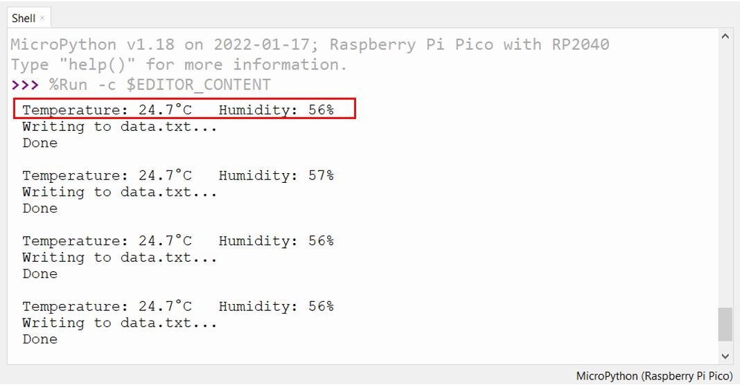
Upload the main.py file to Raspberry Pi Pico. In the Thonny shell terminal you will see messages confirming that the SD card was mounted and that data is being written every 30 seconds. The temperature and humidity values are also printed on each iteration so you can confirm the sensor is reading correctly.
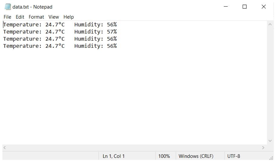
After letting the logger run for a few minutes, remove the microSD card from the module and insert it into your computer. Open the data.txt (or data.csv) file to view the accumulated readings.
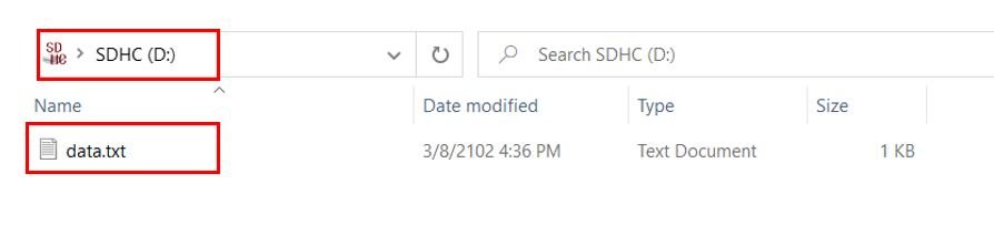
Inside the file you will find lines of logged data, each containing the temperature in degrees Celsius and the relative humidity in percentage, one reading per line.
Troubleshooting
If the project does not work as expected, the following common issues and solutions should help you diagnose and fix the problem.
OSError: no SD card — The driver could not communicate with the card during initialization. Check that VCC and GND are connected correctly, verify all four SPI wires (MISO, MOSI, SCK, CS) are properly seated, and confirm the card is fully inserted into the module. Try lowering the SPI baudrate to 400000 if the issue persists on longer or lower-quality wiring.
OSError: [Errno 22] EINVAL when mounting — The card is not formatted as FAT32, or the partition table is corrupted. Remove the card, reformat it as FAT32 on your computer, and try again.
DHT22 sensor error / invalid checksum — The DHT22 requires a minimum of 2 seconds between consecutive measurements. If you call sensor.measure() too frequently it will raise an exception. Also check that the 10k pull-up resistor is present if you are using the bare sensor (not the breakout module). A loose or missing pull-up causes the data line to float, resulting in corrupted readings.
Data not saved after power loss — Always close the file after each write (or use a with block). The FAT filesystem buffers writes in RAM and only updates the directory entry when the file is closed. If power is cut before closing, the most recently written data may be lost. For maximum safety, consider calling uos.sync() after each write to flush pending changes to the card.
File grows too large — For long-running deployments, log files can eventually fill the card. Consider rotating the file daily by including the date in the filename, or checking available space with uos.statvfs("/sd") before writing and creating a new file when free space falls below a threshold.
Conclusion
In this tutorial, we built a complete DHT22 data logger using Raspberry Pi Pico and MicroPython. We covered sensor wiring, microSD card formatting, installing the sdcard.py driver, writing temperature and humidity readings to a text file, and logging data in CSV format for easy spreadsheet import. We also added error handling and troubleshooting guidance to help you get reliable results in real-world deployments. With this foundation, you can extend the project further — for example, adding a real-time clock module to timestamp each reading, or logging data from multiple sensors simultaneously.
You may also like these related SD card guides:
- BME280 Data Logger with Arduino and Micro SD Card
- DHT22 Data Logger with Arduino and Micro SD Card
- GPS Data Logger with Arduino and Micro SD Card – GPS Tracker
SD card interfacing with other development boards:
nice