In this tutorial, we will look at the workings of a DC-to-DC buck converter. At first, we will discuss the introduction of the DC-to-DC buck converter. Then we will look at the workings of this circuit. Finally, we will design a Simulink model and simulate it. After this, we will see the results. At the end, we will provide a video demonstration of the DC-to-DC buck converter simulation using Simulink.
Introduction of DC-to-DC Buck Converter
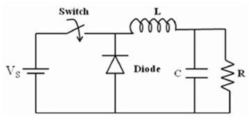
A DC-to-DC buck converter is a converter with which we can step down DC voltages to a desirable level by high-frequency switching of semiconductor switches such as MOSFETs or IGBTs. We can call this type of converter a step-down converter. If we talk about regulated supply, then it is not so difficult on the AC side, but on the DC side it is so much more difficult, and this is only possible with high-frequency switching of semiconductor switches. We can mainly use this type of converter in switch-mode power supplies and DC motor control systems. The schematic diagram of the buck converter is shown below.
Working Principles of DC-to-DC Buck Converter simulation
This DC-to-DC buck converter works in two states: close switch and open switch. When the switch is in a closed state. It causes the diode to be in reverse bias mode, and the input source provides energy to the inductor as well as the output load. Similarly, when the switch is in an open state, the inductor discharges through the diode and transfers some of its stored energy to the output load. Because the switching states of open and close are at such a high frequency. It generates higher orders of harmonics, which require filtering through a low-pass filter.
For turning the switch on or off at high frequency, we use the PWM (pulse width modulation) technique. We can calculate the duty cycle of this PWM using the following formula: D = Vo – Vin / Vo. Here D is the duty cycle, Vo is the output voltage, and Vin is the input voltage. We can see that the output voltage is directly proportional to duty cycle D, meaning that when we increase duty ratio, the output voltage also increases, and when duty cycle decreases, the output voltage also decreases. We will prove this by using the MATLAB Simulink model. The Simulink model is shown below.
Simulink Model
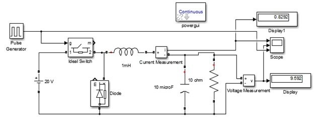
In this MATLAB Simulink model, an ideal switch regulates the 20 V DC voltage into a 10 V DC voltage. The ideal switch is on or off through the pulse generator, which gives the 20 V amplitude switching pulse of 20 KHz frequency at 50% duty ratio. All the calculations for this were done using the duty ratio formula. The output of this converter is not pure DC; it contains high-frequency harmonic content, which we remove through a low-pass filter. In this model, we use a 1 mH inductor and a 10 uF capacitor as low-pass filters. We use a 10 Ohm resistor as an output load. When we simulate this model in Simulink MATLAB, we can see that it shows a 9.562 output voltage and 0.8292 inductor current. Which are shown in the below simulation results.
Simulation
The inductor current, output voltage, and switching pulse of a DC-to-DC buck converter are shown below.

Every dc to dc converter works in two modes of operation: one is CCM (continuous conduction mode), in which the inductor current never goes to zero, and the second is DCM (discontinuous conduction mode), in which the inductor current goes to zero at every switching pulse. As we can see in the above figure, this DC-to-DC buck converter works in CCM mode because the inductor current never goes to zero. When the switching pulse is positive, the inductor charges at its peak value, and during this time, the output capacitor continuously provides the voltage to the output load. Similarly, when the switch pulse is negative, this inductor discharges through the diode and charges the capacitor. This process continues at every switch pulse of the DC-to-DC buck converter.
Video of Simulation
Conclusion
In conclusion, this tutorial provides an overview of simulating a DC-to-DC buck converter with the help of Simulink. It provides an explanation of basic principles along with working concepts to help us better understand the concept. You can utilize this concept to design and simulate more complex circuits in Simulink. Hopefully, this tutorial was helpful in expanding your knowledge in regards to simulation using Simulink.
You may also like to read:
- Stepper Motor Interfacing with TM4C123 Tiva Launchpad
- Voltage Sensor Module Interfacing with Arduino – DC Voltage Measurement
- ESP32 Erase Flash Memory Perform Factory Reset
- BME680 with ESP32 using Arduino IDE (Gas, Pressure, Temperature, Humidity)
- ATMega32 Microcontroller
- ESP32-CAM Take Photo and Save to MicroSD Card with Timestamp Date and Time
This concludes today’s article. If you face any issues or difficulties, let us know in the comment section below.
I want to calculate the transfer function in matlab simulink. In this tutorial, I put the input perturbation point in the pulse generator wire (connect to the gate of the mosfet). I put the output measurement point in the output voltage. Bu transfer function is wrong actually there is nothing. Also bode diagram and step response graph is empty. What is the problem here ? Can you help me ?