In this tutorial, we will learn to interface DS1307 RTC module with ESP8266 NodeMCU board. Firstly, we will look into these questions: What is RTC (Real-time clock)? Why real-time clock is used? How a RTC module communicates with ESP8266 on an I2C communication bus? How to make a digital clock using ESP8266 and DS1307 RTC module? Secondly, we will discuss pinout, pin configuration details, interfacing circuit with ESP8266, and example code at the end.
We have similar guides with ESP32 and Arduino:
- ESP32 Real Time Clock (RTC) using DS1307 Module and display on OLED
- Interface DS1307 RTC Module with Arduino – Display Date/Time on OLED
What is RTC or Real time Clock?
As its name suggests, a real-time clock is used to keep a record of the time and to display time. It is used in many digital electronic devices like computers, digital smartwatches, data loggers, and situations where you need to keep track of time. one of the great benefits of a real-time clock is that it also keeps a record of time even if the power supply is not available.
Now the question is how can an electronics device like real-time clockwork without the use of a power supply. Because almost all RTC modules come with small coin size 20mm 3V lithium coin cells which can work for years. Usually, CR2032 coil cells are used.
DS1307 RTC IC
At the center of the DS1307 RTC module is an 8-pin DS1307 chip. It provides a real-time clock that is used to keep track of seconds, minutes, hours, days, months, and years. It uses the I2C communication protocol for communicating with other devices like in our case we are using ESP32. ESP32 reads values of time and date from DS1307 using the I2C communication protocol. Moreover, it also has a feature to keep a record of the exact time in case of power failure with the help of a backup battery. It is used to make a real-time clock using some other electronic components.
DS1307 Chip Pinout
The following figure shows the pinout diagram of DS1307 IC.
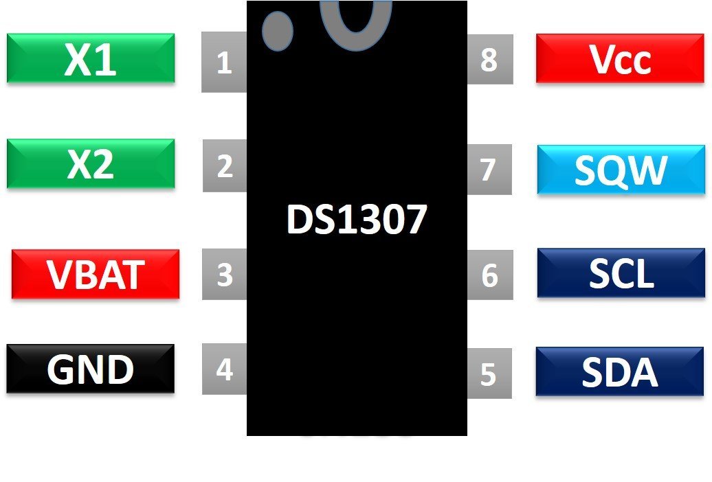
Now let’s see the functionality of each pin one by one.
- X1 and X2 are used for crystal oscillators. The crystal oscillator value usually used with DS1307 is 32.768k Hz.
- VBAT: Connect a CR2032 coil cell as backup power. Its value should be between 3-5 volt. voltage more than 5 volts may burn DS1307 permanently. A backup battery is used to keep track of time in case of power failure.
- Vcc and GND are power supply pins
- SDA and SCL are used to communicate with other devices over of I2C communication bus.
- SQW pin provides square waves of different frequencies such as 1Hz, 4kHz, 8kHz, or 32kHz. The frequency of output wave can be selected by sending a signal to DS1307 over an I2C bus.
If you want to use this IC directly with ESP8266, you need to use external components to connect with DS1307. The following circuit diagram shows the connections of all required components with DS1306:
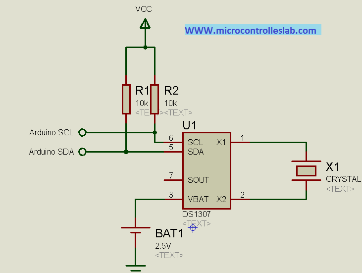
But instead of using DS1307 chip alone and making your own PCB design, you can get a ready to use DS1307 RTC module in very low cost.
DS1307 RTC Module
DS1307 RTC module has all onboard components which are required for the correct functionality of a DS3107 chip. On top of that, it contains a holder to connect a 20mm 3V lithium coin cell. This holder can contain any CR2032 battery. Now let’s discuss the components of this module one by one.
At the center of the DS1307 RTC module is a chip which we have discussed earlier. This chip keeps track of seconds, minutes, hours, days, and months. At the end of every month, this chip automatically adjusts its seconds, minutes, hours, and date. It is also possible to configure time display in 12-hour with an AM and PM or 24-hour format.

32kHz Crystal Oscillator
As discussed earlier, the DS1307 chip requires 32KHz of an external crystal oscillator for its operation (time-keeping). Therefore, the RTC module comes with 32KHz of an external crystal oscillator.
But there is one problem with this 32KHz crystal oscillator that is a change in environmental temperature affects the oscillation frequency of the crystal oscillator. This change in 32KHz of external crystal oscillation frequency is negligible. But it shows an error in the long run. It gives a clock drift of 2-3 minutes per month.
Onboard 24C32 EEPROM
DS1307 RTC module also contains onboard 24C32 EEPROM. This EEPROM can store 32 bytes and have limited read-write operations. We can use this memory to save time when we want to use an RTC module for Alarm based projects. For example, we want to set an alarm at 8:00 AM every day. We can save this time value into EEPROM and whenever the time matches with this saved value, an alarm starts.
These EEPROM chips also communicate with microcontrollers over the I2C bus. Hence, it shares the same I2C bus as DS1307. Different slave addresses are assigned to EEPROM (o 0x50 Hex) and DS1307 chip to communicate with them on the same I2C bus.
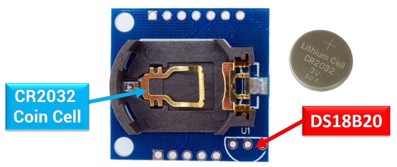
Backup Battery
On the back side of a RTC module, there is a holder to connect the CR2032 coil cell. This backup battery is used to keep track of time accuracy even when the main power source which is connected to DS1307 fails. This chip contains a power sensing circuitry which senses the main power and whenever the main power shutdown, it switches to the backup coil cell.
In backup mode, DS1307 consumes only 300nA current. That means a backup battery based on a coin cell can work for more than 17 years. Because, generally, the capacity of CR2032 battery is 47mAh and chip consumes only 300nA when powers through a battery.
Life_time = 47mAh/300nA = 156666 hours = 6527 days = 17+ years
DS18B20 Sensor
There is an empty slot available on this module to connect an external DS18B20 digital thermometer. The three empty pinouts in the bottom right corner is a place holder for the DS18B20 sensor and output of the sensor can be received from DS pin of RTC module.
DS1307 RTC Module Pinout
The following figure shows the pinout diagram. This module exposes a total of 7 pins out of which two are power supply pins and two are for SCL and SDA pins for the I2C communication bus. We have already seen the functionality of all these pins in the previous sections.

DS1307 and ESP8266 Wiring Diagram
As mentioned previously, the DS1307 module uses I2C communication protocol to communicate with the microcontroller. For ESP8266, the default I2C pin for SDA is GPIO4 and for SCL is GPIO5..
First make connections with DS1307 RTC module and ESP8266 according to this connection diagram:

| ESP8266 | DS1307 RTC Module |
|---|---|
| Vin | VCC |
| GND | GND |
| GPIO4 (D2) | SDA |
| GPIO5 (D1) | SCL |

Setting up Arduino IDE
We will use Arduino IDE to program our ESP8266 development board. Thus, you should have the latest version of Arduino IDE. Additionally, you also need to install the ESP8266 plugin. If your IDE does not have the plugin installed you can visit the link below:
Install DS1307 Library In Arduino IDE
To program a DS1307 RTC module, we use I2C communication pins of ESP8266. If you don’t understand about I2C communication, you can read this report:
But it demands an exercise to write a code from scratch. Luckily, an Arduino RTClib library is available, which implements callback functions to get time measurements from an RTC module. This library hides all the complexity to interact with an RTC module over I2C communication. We can use simple callback functions implemented by RTClib to read data from DS1307.
Therefore, to program a DS1307 RTC module with ESP8266, you will use the RTClib library available in Arduino IDE.
To apply this library, first, we need to install this library in Arduino IDE by going to Arduino’s library manager. Open Arduino IDE, go to Tools > Manage Libraries.

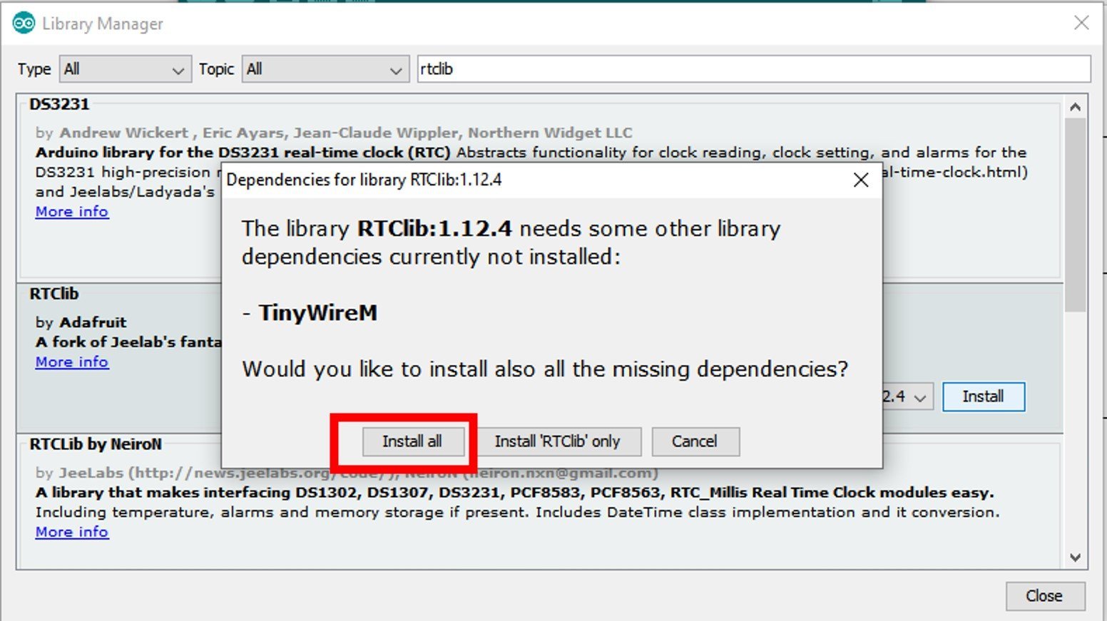
After that, this window library manager window will appear. Search for “RTClib” by typing in the search bar. You will see many options for DS1307. But the one that we will use in this tutorial is RTClib by Adafruit. Select RTClib by Adafruit and click on the install button.

When you click on the install button, you may get a message that RTClib may require other libraries dependencies which is currently not installed in your Arduino IDE. We recommend you to install all dependencies by clicking on install button. Otherwise, RTClib will not work properly.
ESP8266 Arduino Sketch Real Time Clock with DS1307 Module
Open your Arduino IDE and go to File > New to open a new file. Copy the code given below in that file.
// Date and time functions using a DS1307 RTC connected via I2C and Wire lib
#include "RTClib.h"

RTC_DS1307 DS1307_RTC;

char Week_days[7][12] = {"Sunday", "Monday", "Tuesday", "Wednesday", "Thursday", "Friday", "Saturday"};

void setup () {
  Serial.begin(115200);

#ifndef ESP8266
  while (!Serial); // wait for serial port to connect. Needed for native USB
#endif

  if (!DS1307_RTC.begin()) {
    Serial.println("Couldn't find RTC");
    while(1);
  }
   DS1307_RTC.adjust(DateTime(F(__DATE__), F(__TIME__)));
}

void loop () {
    DateTime now = DS1307_RTC.now();

    Serial.print(now.year(), DEC);
    Serial.print('/');
    Serial.print(now.month(), DEC);
    Serial.print('/');
    Serial.print(now.day(), DEC);
    Serial.print(" (");
    Serial.print(Week_days[now.dayOfTheWeek()]);
    Serial.print(") ");
    Serial.print(now.hour(), DEC);
    Serial.print(':');
    Serial.print(now.minute(), DEC);
    Serial.print(':');
    Serial.print(now.second(), DEC);
    Serial.println();

    Serial.print(" since midnight 1/1/1970 = ");
    Serial.print(now.unixtime());
    Serial.print("s = ");
    Serial.print(now.unixtime() / 86400L);
    Serial.println("d");

    // calculate a date which is 7 days, 12 hours, 30 minutes, 6 seconds into the future
    DateTime future (now + TimeSpan(7,12,30,6));

    Serial.print(" now + 7d + 12h + 30m + 6s: ");
    Serial.print(future.year(), DEC);
    Serial.print('/');
    Serial.print(future.month(), DEC);
    Serial.print('/');
    Serial.print(future.day(), DEC);
    Serial.print(' ');
    Serial.print(future.hour(), DEC);
    Serial.print(':');
    Serial.print(future.minute(), DEC);
    Serial.print(':');
    Serial.print(future.second(), DEC);

    Serial.println();
    Serial.println();
    delay(3000);
}
How the Code Works?
We will start off by including the necessary libraries for this project. The RTClib.h will help us access functions to build the RTC.
#include "RTClib.h"Next create an object of RTC_DS1307 called ‘DS1307_RTC.’
RTC_DS1307 DS1307_RTC;Also, create a 2d array of characters called ‘Week_days’ that holds the days of the week.
char Week_days[7][12] = {"Sunday", "Monday", "Tuesday", "Wednesday", "Thursday", "Friday", "Saturday"};setup()
Inside our setup() function, we will initialize the serial communication at a baud rate of 112500.
Serial.begin(115200); Moreover, we will also initialize the RTC module by using DS1307_RTC.begin().
  if (!DS1307_RTC.begin()) {
    Serial.println("Couldn't find RTC");
    while(1);
  }
After that we call DS1307_RTC.adjust(DateTime(F(DATE), F(TIME))) function. This function is responsible for aligning the time according to our computer.
DS1307_RTC.adjust(DateTime(F(__DATE__), F(__TIME__)));loop()
Inside the loop() function, we acquire the current date and time using DS1307_RTC.now() and save it in the variable DateTime now.
DateTime now = DS1307_RTC.now();Then, we display the current date, day and time on the serial monitor. Moreover, the time since midnight of 1/1/1970 is also printed along with the future date and time.
Serial.print(now.year(), DEC);
    Serial.print('/');
    Serial.print(now.month(), DEC);
    Serial.print('/');
    Serial.print(now.day(), DEC);
    Serial.print(" (");
    Serial.print(Week_days[now.dayOfTheWeek()]);
    Serial.print(") ");
    Serial.print(now.hour(), DEC);
    Serial.print(':');
    Serial.print(now.minute(), DEC);
    Serial.print(':');
    Serial.print(now.second(), DEC);
    Serial.println();

    Serial.print(" since midnight 1/1/1970 = ");
    Serial.print(now.unixtime());
    Serial.print("s = ");
    Serial.print(now.unixtime() / 86400L);
    Serial.println("d");

    // calculate a date which is 7 days, 12 hours, 30 minutes, 6 seconds into the future
    DateTime future (now + TimeSpan(7,12,30,6));

    Serial.print(" now + 7d + 12h + 30m + 6s: ");
    Serial.print(future.year(), DEC);
    Serial.print('/');
    Serial.print(future.month(), DEC);
    Serial.print('/');
    Serial.print(future.day(), DEC);
    Serial.print(' ');
    Serial.print(future.hour(), DEC);
    Serial.print(':');
    Serial.print(future.minute(), DEC);
    Serial.print(':');
    Serial.print(future.second(), DEC);

    Serial.println();
    Serial.println();
    delay(3000);
Demonstration
Choose the correct board and COM port before uploading your code to the board. Therefore go to Tools > Board and select NodeMCU 1.0.
Select the NodeMCU module as follows:

Then, go to Tools > Port and select the appropriate port through which your board is connected.
Click on the upload button to upload the code to ESP8266 development board.
After you have uploaded your code to the ESP8266 development board, press its RST button.

In your Arduino IDE, open up the serial monitor and set the baud rate to 115200. The serial monitor will start displaying the current date and time along with future date and time and time since midnight of 1/1/1970.

OLED with DS1307 and ESP8266

We will require the following components for this project.
- ESP8266 board
- DS1307 RTC Module with Coin Cell
- SSD1306 OLED Display
- Connecting Wires
- Breadboard
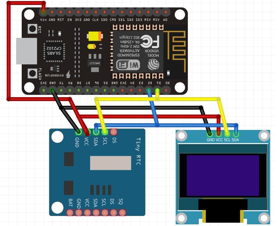
As mentioned previously, the DS1307 module uses I2C communication protocol to communicate with the microcontroller. The SSD1306 OLED that we are using also has an I2C interface. Hence, we will use the same I2C pins of ESP8266 to connect with both the RTC module and the OLED.
We will connect the VCC terminals of the OLED and the RTC Module with Vin of ESP8266 board. SCL of the display and the RTC module will be connected with the SCL pin of ESP8266. Likewise, the SDA of the display and RTC module will be connected with the SDA of ESP8266. The ground of all the devices will be held common.
The connections between the three devices can be seen below:
| ESP8266 board | DS1307 Module | SSD1306 OLED Display |
|---|---|---|
| Vin | VCC | VCC |
| GPIO4 (D2) | SDA | SDA |
| GPIO5 (D1) | SCL | SCL |
| GND | GND | GND |
Follow the schematic diagram below to connect the devices.
Install SSD1306 OLED Library
To use the OLED display in our project, we have to install the Adafruit SSD 1306 library and Adafruit GFX library in Arduino IDE. Follow the steps below to successfully install them.
Open Arduino IDE and click on Sketch > Library > Manage Libraries
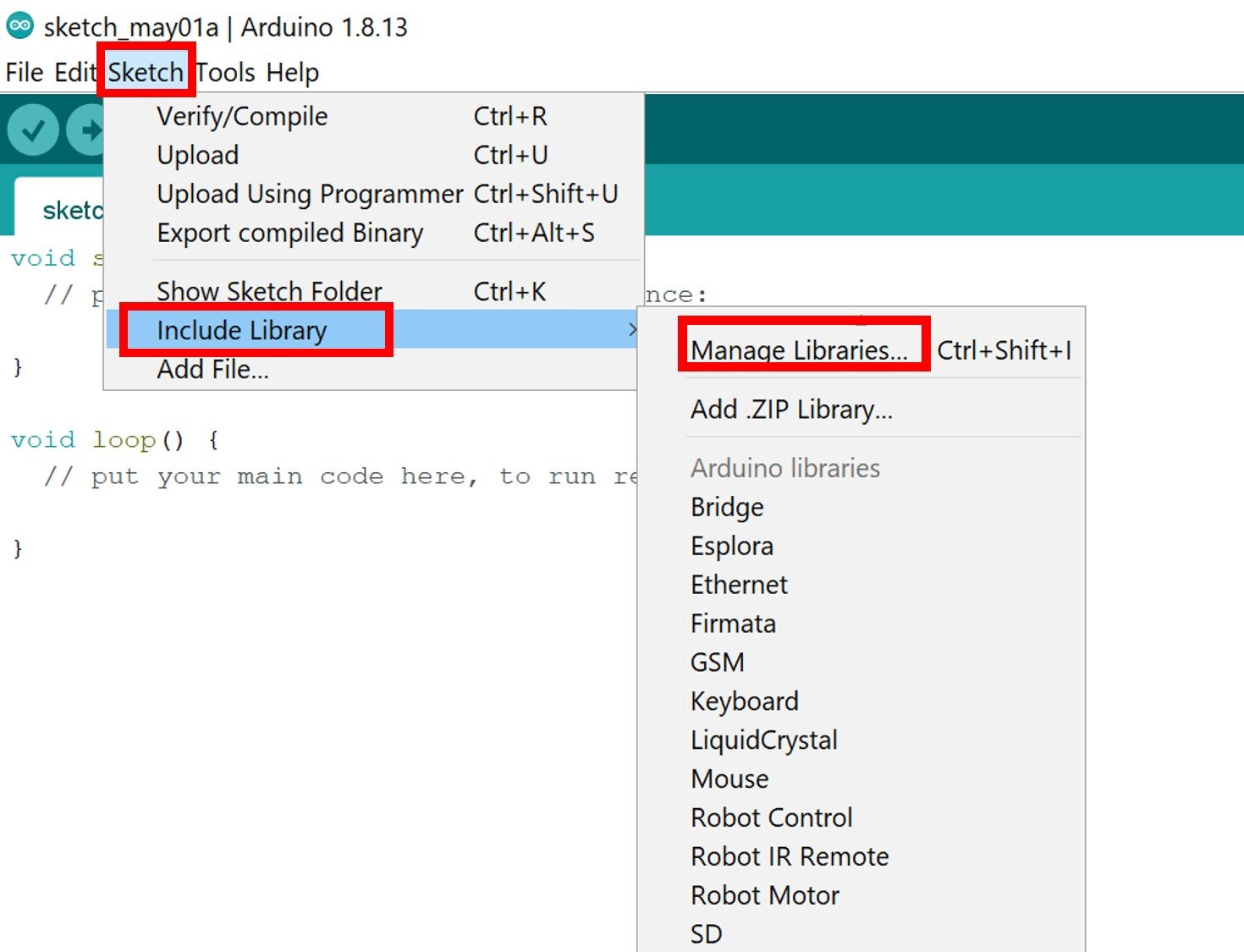
The following window will open up.

Type ‘SSD1306’ in the search tab and install the Adafruit SSD1306 OLED library.

We will also require the Adafruit GFX library which is a dependency for SSD1306. Type ‘Adafruit GFX’ in the search tab and install it as well.
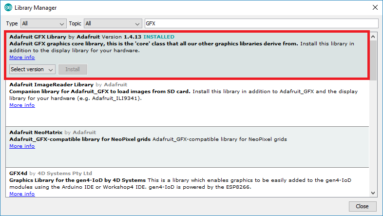
After installing the libraries, restart your IDE.
Arduino Code OLED and DS1307
Open your Arduino IDE and go to File > New to open a new file. Copy the code given below in that file.
#include <Wire.h>
#include <Adafruit_GFX.h>
#include <Adafruit_SSD1306.h>
#include "RTClib.h"

#define SCREEN_WIDTH 128 // OLED display width, in pixels
#define SCREEN_HEIGHT 64 // OLED display height, in pixels

// Declaration for an SSD1306 display connected to I2C (SDA, SCL pins)
Adafruit_SSD1306 display(SCREEN_WIDTH, SCREEN_HEIGHT, &Wire, -1);
RTC_DS1307 RTC;
char days[7][12] = {"Sunday", "Monday", "Tuesday", "Wednesday", "Thursday", "Friday", "Saturday"};

void setup() {
  Serial.begin(115200);

  if (!RTC.begin()) {
    Serial.println("Couldn't find RTC");
    while (1);
  }
  RTC.adjust(DateTime(F(__DATE__), F(__TIME__)));

  if (!display.begin(SSD1306_SWITCHCAPVCC, 0x3C)) { // Address 0x3C for 128x64
    Serial.println(F("SSD1306 allocation failed"));
    for (;;);
  }
  delay(1000);
  display.clearDisplay();

  display.setTextSize(2);
  display.setTextColor(WHITE);
  display.setCursor(30, 20);
  // Display static text
  display.println("RTC");
  display.display();
  delay(3000);
  display.clearDisplay();
}

void loop() {
  DateTime now = RTC.now();

  display.clearDisplay();
  display.setTextSize(2);
  display.setCursor(0, 0);
  display.print(now.day());
  display.print('/');
  display.print(now.month());
  display.print('/');
  display.print(now.year());
  display.println(days[now.dayOfTheWeek()]);
  display.println(' ');
  display.setCursor(0, 40);
  if (now.hour() < 10)
    display.print('0');
  display.print(now.hour());
  display.print(':');
  if (now.minute() < 10)
    display.print('0');
  display.print(now.minute());
  display.print(':');
  if (now.second() < 10)
    display.print('0');
  display.println(now.second());
  display.display();
}
How the Code Works?
We will start off by including the necessary libraries for this project. Wire.h will allow us to communicate through the I2C protocol. Whereas the OLED libraries are the ones which we previously installed and are required for the proper functionality of the OLED display. The RTClib.h will help us access functions to build the RTC.
#include <Wire.h>
#include <Adafruit_GFX.h>
#include <Adafruit_SSD1306.h>
#include "RTClib.h"
Next create an object of RTC_DS1307 called ‘RTC.’
RTC_DS1307 RTC;Also, create a 2d array of characters called ‘days’ that holds the days of the week.
char days[7][12] = {"Sunday", "Monday", "Tuesday", "Wednesday", "Thursday", "Friday", "Saturday"};Then, we will initialize the OLED display by creating an object of Adafruit_SSD1306 and specifying the width, height, I2C instance (&Wire), and -1 as parameters inside it.’ -1′ specifies that the OLED display which we are using does not have a RESET pin. If you are using the RESET pin then specify the GPIO through which you are connecting it with your development board.
#define SCREEN_WIDTH 128 // OLED display width, in pixels
#define SCREEN_HEIGHT 64 // OLED display height, in pixels

// Declaration for an SSD1306 display connected to I2C (SDA, SCL pins)
Adafruit_SSD1306 display(SCREEN_WIDTH, SCREEN_HEIGHT, &Wire, -1);
setup()
Inside our setup() function, we will initialize the serial communication at a baud rate of 112500.about:blank
Serial.begin(115200); Moreover, we will also initialize the OLED display and the RTC module by using display.begin() and RTC.begin() respectively. Make sure you specify the correct address of your OLED display. In our case, it is 0X3C.
 if (!RTC.begin()) {
    Serial.println("Couldn't find RTC");
    while (1);
  }


  if (!display.begin(SSD1306_SWITCHCAPVCC, 0x3C)) { // Address 0x3C for 128x64
    Serial.println(F("SSD1306 allocation failed"));
    for (;;);
  }
After that we call RTC.adjust(DateTime(DATE, TIME)) function. This function is responsible for aligning the time according to our computer.
RTC.adjust(DateTime(F(__DATE__), F(__TIME__)));Then, we will clear the buffer by using clearDisplay() on the Adafruit_SSD1306 object.
First, we will set the size of the text using setTextSize() and pass the size as a parameter inside it. Next, we will control the color of the text by using the setTextColor() function and passing WHITE as an argument. We will use the setCursor() function to denote the x and the y axis position from where the text should start. Then we print the text ‘RTC’ on the display for 3 seconds using display.println().
  display.clearDisplay();

  display.setTextSize(2);
  display.setTextColor(WHITE);
  display.setCursor(30, 20);
  // Display static text
  display.println("RTC");
  display.display();
  delay(3000);
  display.clearDisplay();
loop()
Inside the loop() function, we acquire the current date and time using RTC.now() and save it in the variable DateTime now.
DateTime now = RTC.now();Then, we display the time in HH:MM:SS along with the day, date, month and year on the OLED. This is achieved by first clearing the display, setting the text size, setting the cursor position and then printing the text using display.println().
display.clearDisplay();
  display.setTextSize(2);
  display.setCursor(0, 0);
  display.print(now.day());
  display.print('/');
  display.print(now.month());
  display.print('/');
  display.print(now.year());
  display.println(days[now.dayOfTheWeek()]);
  display.println(' ');
  display.setCursor(0, 40);
  if (now.hour() < 10)
    display.print('0');
  display.print(now.hour());
  display.print(':');
  if (now.minute() < 10)
    display.print('0');
  display.print(now.minute());
  display.print(':');
  if (now.second() < 10)
    display.print('0');
  display.println(now.second());
  display.display();
Demonstration
Choose the correct board and COM port before uploading your code to the board. Therefore go to Tools > Board and select NodeMCU 1.0.
Select the NodeMCU module as follows:
Then, go to Tools > Port and select the appropriate port through which your board is connected.
Click on the upload button to upload the code to ESP8266 development board.
After you have uploaded your code to the ESP8266 development board, press its RST button.
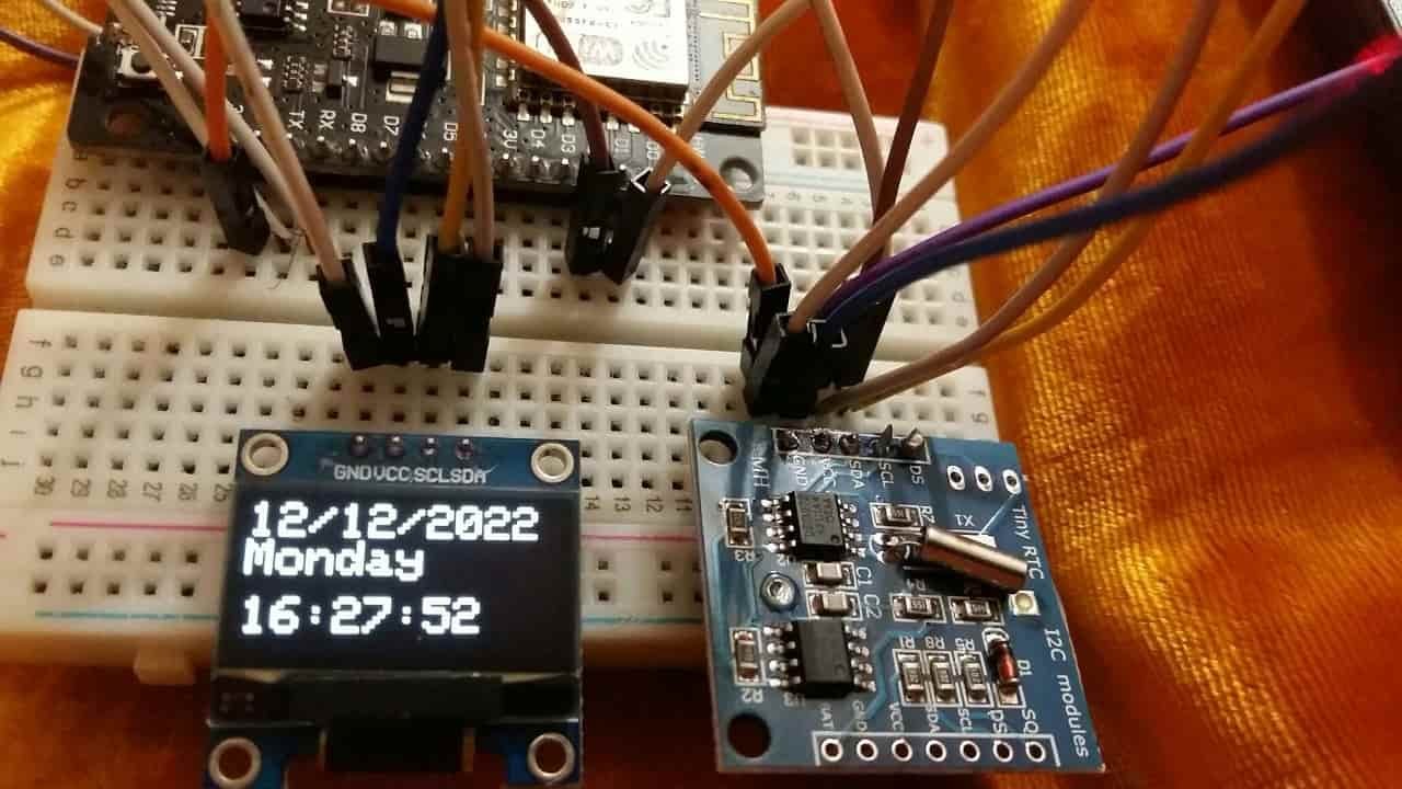
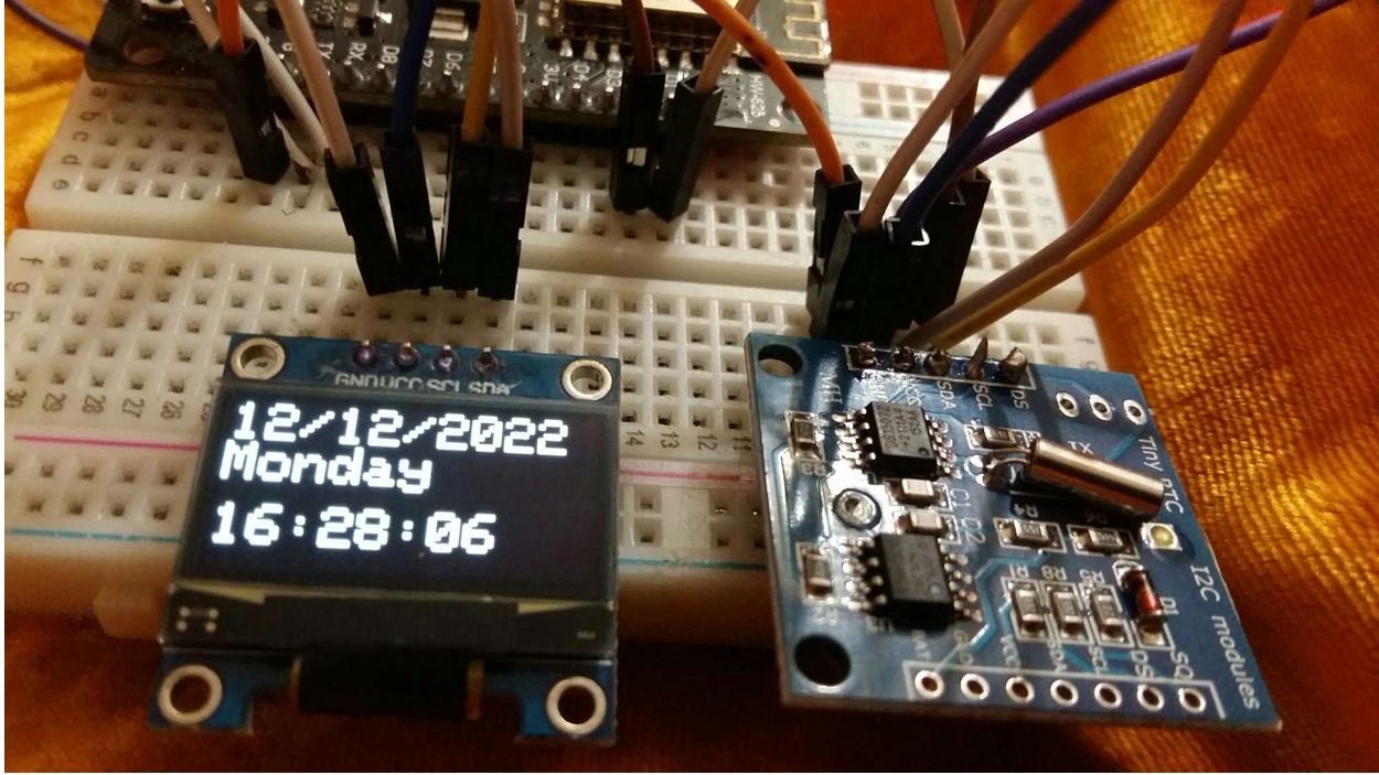
The OLED will start displaying the current date, day and time.
Video demo:
You may also like to read:
- ESP8266 NodeMCU Real Time Clock (RTC) with DS3231 and OLED
- IoT Based Analog and Digital Clock using OLED and ESP32/ESP8266
- Internet Based Digital Clock using ESP32 and MAX7219 Dot Matrix Display
- Interface DS1307 RTC Module with Arduino – Display Date/Time on OLED
- Digital clock ds1307 using PIC microcontroller
- Interface DS3231 RTC Module with Arduino – Set/Read Date and Time