In this tutorial, we will discuss the workings of a three phase voltage source inverter. We will design and simulate it with the help of Simulink. At first, we will provide an introduction to the three phase voltage source. Then, we will design the Simulink model, simulate it, and compare the results with the theoretical discussion.
Introduction to Three Phase Voltage Source Inverter
The three-phase voltage source inverter inverts the DC voltages into three phase AC voltages. Normally, we use two types of inverters with respect to their phases: a single-phase voltage source inverter for low-power applications and a three-phase voltage source inverter for high-power applications. Thus, the main advantage of these types of inverters is that they are controllable voltage source inverters, meaning we can easily control the frequency, amplitude, and voltage. Usually, these have applications in UPS (Uninterruptible Power Supply), ASDs (Adjust Speed Drives), and FACTs (Flexible Alternating Current Transmission System) devices.
Simulink Model Design of Three Phase Voltage Source Inverter
In this article, we will explain how we make a three-phase voltage source inverter in MATLAB Simulink, as well as how we make a new model with the help of power electronics components. First, we will open MATLAB and then click on the MATLAB Simulink library. The MATLAB Simulink library browser will open on a new page, as shown in the figure below.
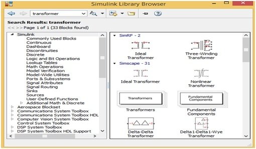
This MATLAB Simulink library browser has different options on their menu bar, but for making a new simulating circuit, first we must need a new model, and then click on the new model option. The new model will open on a new page, as shown in the figure below.

Components Library Simulink
On this new MATLAB Simulink model, we can easily make our new circuits as we want. At first, we will make a new circuit, and then we will choose the power electronics components. So, for choosing power electronics components, we will just write the word power electronics on the search menu bar of the MATLAB Simulink library browser, and a new page will open with different blocks of power electronics components. We can see this in the figure below.

We can easily drag these power electronics blocks onto a new MATLAB Simulink model by clicking on any specific block. We can also add these blocks to a new model by right-clicking on any block and then selecting the option Add Block to a “New Model”. This will automatically add the block to the new Simulink model. Similarly, for choosing the other blocks such as display and oscilloscope, just write the word sink in the MATLAB Simulink library, and a new page will open. We can see this in the figure below.

Simulink Model
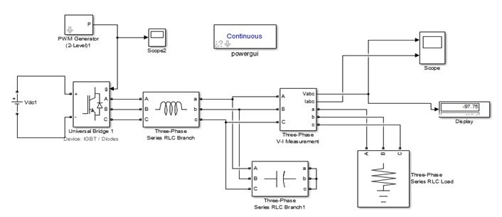
Similarly, we can choose and drag all the other blocks, such as inductor, capacitor, voltmeter, ammeter, PWM generator, sine wave generator, etc. Here we have made a three-phase voltage source inverter with the help of these Simulink blocks, which are shown in figure below.
Setting Parameters
This three phase voltage source inverter has been made with the help of a three phase universal bridge block whose parameters are set according to the figure below and has been powered up with DC 314 V.

We use a two-level PWM generator to give the pulses to the three arms of this universal bridge. The parameters are set for this PWM generator block according to the figure below.

Simulation
The output of this three phase voltage source inverter is not pure AC; it consists of higher-order harmonic content; therefore, the circuit requires an LC filter to gain pure AC. Here we connect a three-phase LC filter, which has an inductance of 40 mH and a capacitance of 120 μF. Then we provide a 1 KW load at the output. Its voltage, current waveforms, and PWM generator pulses are shown in the figures below.
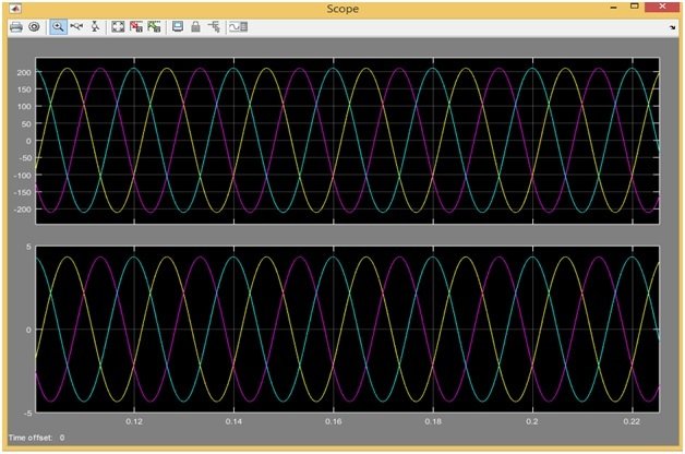

So this is the simulation of our designed model in Simulink. Hence, we can say that the design of our three phase voltage source inverter is working effectively.
Video Demonstration
Conclusion
In conclusion, this tutorial provides an in-depth overview of designing and simulating a three-phase voltage source inverter using Simulink. It covers step-by-step procedures with examples along with explanations to help us better understand the concept. You can utilize this to design and simulate more complex models using Simulink. Hopefully, this was helpful in expanding your knowledge in regards to designing and simulating models with the help of Simulink.
You may also like to read:
- ESP32 ESP-NOW Getting Started Tutorial with Arduino IDE
- GPIO External Interrupts STM32 Nucleo with STM32CubeIDE
- LCD Interfacing with TM4C123 Tiva LaunchPad – Keil uvision
- HC-05 Bluetooth Interfacing with TM4C123G Tiva C Launchpad – Keil uvision
- I2C LCD interfacing with ESP32 and ESP8266 in Arduino IDE
- ESP32 Bluetooth Classic with Arduino IDE: Getting Started Guide
This concludes today’s article. If you face any issues or difficulties, let us know in the comment section below.
Sir,
I have simulated this project but the the 3 phase AC signal I am getting is distorted.
1)Amplitude distortion
The peak of output sine wave is increasing and then decreasing as the cycle proceeds.This is happening in all the three phases.
2)Phase distortion
In all the three phases of output phase is not proper. It appears like a tilted sine wave.
In my block parameter for Universal Bridge [Tf, Tt] parameter is absent.
Please help me out.
how to connect MPPT Boost Converter to this voltage source inverter