In this tutorial, we will explore how to use the Bluetooth Classic on ESP32 with Arduino IDE. For demonstration, we will establish bidirectional data communication between the ESP32 and an Android cell phone over Bluetooth Classic. Firstly, we will see a simple example to send data from ESP32 to an Android app. After that, we will make a demo project to send any sensor readings to an Android app. As an example, we will use a DS18B20 temperature sensor with ESP32 to transmit temperature readings to an Android smartphone using ESP32 Bluetooth Classic.
You may also like to read about the ESP32 BLE module:
ESP32 Bluetooth Low Energy (BLE) using Arduino IDE
In this tutorial, we will learn the following:
- Transfer data to Andriod app with ESP32 Bluetooth
- Send DS18B20 Temperature readings to Andriod app
- Controlling ESP32 GPIO with Andriod app
Recommended Components
The following components are used in this project or are helpful for building it with the ESP32.
| Component | How it’s used in this project | Buy on Amazon |
|---|---|---|
| ESP32 Development Board (DevKit V1) | The main board that runs the project firmware. | Check Price |
| Micro USB Cable | Connects the board to your computer to upload code and power it. | Check Price |
| Breadboard | Holds the board and components together while you wire up the project. | Check Price |
| Jumper Wires | Make the connections between the board and any external parts. | Check Price |
As an Amazon Associate we earn from qualifying purchases. Prices and availability are accurate as of the date/time indicated and are subject to change.
Bluetooth Classic
Bluetooth Classic, also known as “Bluetooth Basic Rate/Enhanced Data Rate” (BR/EDR), is one of the two main Bluetooth communication protocols, the other being Bluetooth Low Energy (BLE). It was the original version of Bluetooth, introduced in 1999, and is designed for various applications that require relatively high data transfer rates.
Range
Bluetooth Classic operates in the 2.4 GHz ISM (Industrial, Scientific, and Medical) band and provides robust wireless communication between devices over short distances, typically up to 10 meters. It offers a maximum data transfer rate of up to 3 Mbps, making it suitable for applications like audio streaming, file transfer, and wireless peripherals such as keyboards, mice, and speakers.
Advantages
One of the advantages of Bluetooth Classic is its backward compatibility with older Bluetooth devices, ensuring interoperability between different generations of Bluetooth-enabled products. This has contributed to its widespread adoption in various consumer electronics, automotive systems, and industrial applications.
However, with the emergence of Bluetooth Low Energy, Bluetooth Classic is now more commonly used in applications that demand higher data rates and continuous data streaming. As the technology landscape evolves, developers can choose between Bluetooth Classic and Bluetooth Low Energy based on the specific requirements of their projects, each protocol catering to different use cases in the realm of wireless communication.
In this tutorial, we will focus on Classic Bluetooth which is designed for a connection-oriented one-to-one two-way data transfer.
ESP32 Bluetooth Classic
The ESP32, being a versatile and powerful microcontroller, can act as both a Bluetooth Classic device (using Bluetooth Basic Rate/Enhanced Data Rate) and a Bluetooth Low Energy (BLE) device.
When using Bluetooth Classic on the ESP32, the microcontroller can establish connections with other Bluetooth Classic devices, such as smartphones, computers, or other peripherals. This enables data exchange over short distances, allowing the ESP32 to send and receive information like audio, files, and commands. Bluetooth Classic is well-suited for applications that require relatively higher data transfer rates, making it suitable for audio streaming or sending larger amounts of data quickly.
The ESP32’s support for Bluetooth Classic and BLE gives developers the flexibility to choose the appropriate Bluetooth technology based on their project requirements. For instance, if a project needs to connect to older Bluetooth devices or requires higher data rates, Bluetooth Classic can be the preferred choice on the ESP32. On the other hand, if low power consumption and wireless sensor applications are the priority, developers can opt for BLE on the ESP32. This flexibility empowers developers to design a wide range of wireless applications with the ESP32, catering to various use cases in the Internet of Things (IoT), home automation, and smart device domains.
Android Smart Phone Terminal Application
In this guide, we will connect our ESP32 development board to an Android smartphone. To do this, you’ll need an Android phone and a Bluetooth terminal application. The Bluetooth terminal app helps link the two devices together, allowing them to communicate. So, make sure you have your Android phone ready to follow along with the steps.
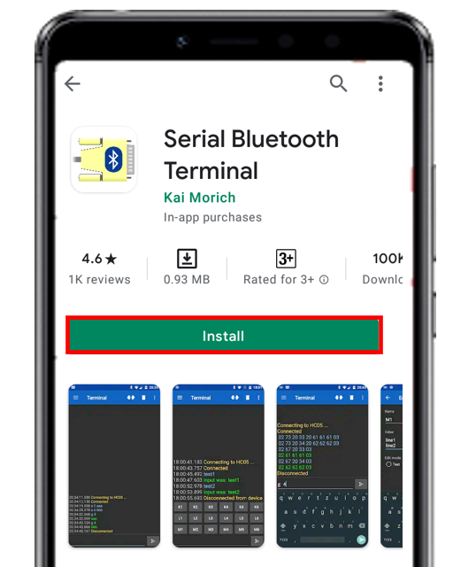
Go to the Play Store and download the application by the name: Serial Bluetooth terminal. This can be seen in the figure below.
ESP32 Bluetooth Classic Example Transmit Data to Andriod App
Arduino IDE does not come with the ESP32 installed by default. Before proceeding further, make sure you have the ESP32 add-on installed in your IDE. We will use an example sketch from the Arduino IDE. This is already available in the Bluetooth Serial library. It will demonstrate how two devices can be connected through serial communication.
- Open your Arduino IDE and click on File > Examples > BluetoothSerial > SerialtoSerialBT
- A new file will open which will contain the following program code.
#include "BluetoothSerial.h"

#if !defined(CONFIG_BT_ENABLED) || !defined(CONFIG_BLUEDROID_ENABLED)
#error Bluetooth is not enabled! Please run `make menuconfig` to and enable it
#endif

BluetoothSerial SerialBT;

void setup() {
  Serial.begin(115200);
  SerialBT.begin("ESP32test"); //Bluetooth device name
  Serial.println("The device started, now you can pair it with bluetooth!");
}

void loop() {
  if (Serial.available()) {
    SerialBT.write(Serial.read());
  }
  if (SerialBT.available()) {
    Serial.write(SerialBT.read());
  }
  delay(20);
}
How does the Code Work?
We will first include the BluetoothSerial library. Through this library, we will use the functionalities needed for two-way serial communication over Bluetooth.
#include "BluetoothSerial.h"Then, we will ensure whether Bluetooth is enabled or not. If there is an error associated with it then ensure its proper enablement.
#if !defined(CONFIG_BT_ENABLED) || !defined(CONFIG_BLUEDROID_ENABLED)
#error Bluetooth is not enabled! Please run `make menuconfig` to and enable it
#endif
Next, we will create an object for our BluetoothSerial which we will access later on in the code.
BluetoothSerial SerialBT;Inside the void setup() function, we will start the serial communication with a baud rate of 115200. Then we will pass the name of the Bluetooth device as a parameter inside SerialBT.begin(). By default, it is set as ESP32test but you can change it according to your preference. This will be the name associated with the Bluetooth device or the server. Through the print functionality, we will display on the serial monitor that the device is ready to be paired with Bluetooth.
Serial.begin(115200);
SerialBT.begin("ESP32test"); //Bluetooth device name
Serial.println("The device started, now you can pair it with bluetooth!")
Inside the void loop() function we will use two if statements. One to send data and the second to receive it.
The first if statement checks if there is any data being received through the serial port. It will then send that data to the device which will be paired to the transmitting device through SerialBT.write() function and pass Serial.read() as a parameter inside it. This will return the information which will be received in the serial port.
The second if statement reads for data in the Bluetooth serial port. It checks whether any data is present there SerialBT.read(). If it is then it prints that on the serial monitor of the Arduino IDE through Serial.write() function.
if (Serial.available()) {
  SerialBT.write(Serial.read());
}
if (SerialBT.available()) {
  Serial.write(SerialBT.read());
}
Demonstration
After uploading the above code in your Arduino IDE press the ENABLE button on your ESP32 board.

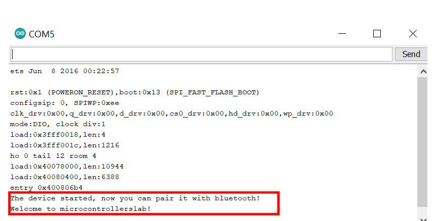
A few moments later, a message will be displayed on the serial monitor as shown below:
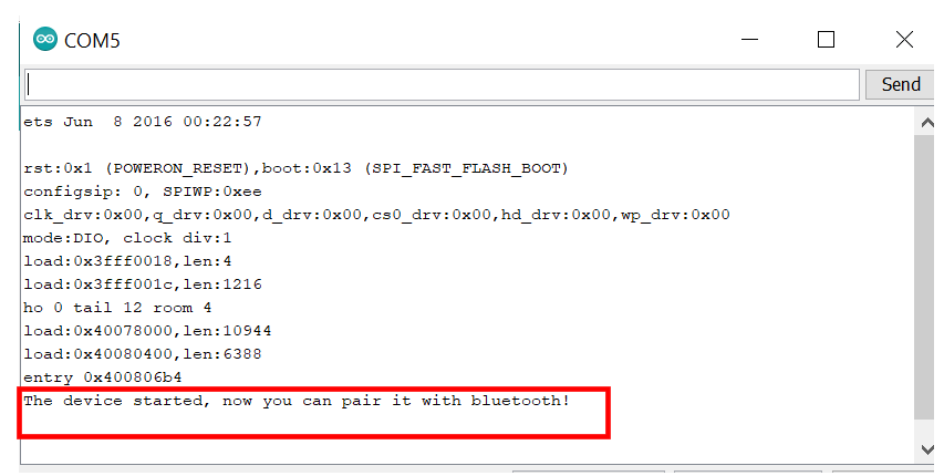
If you see this message, it means that a successful connection was established with your ESP32 module. Now it can perform serial-to-serial communication with another device. We will use an Android smartphone to connect with our ESP32 module. To do that you will have to perform a series of steps.
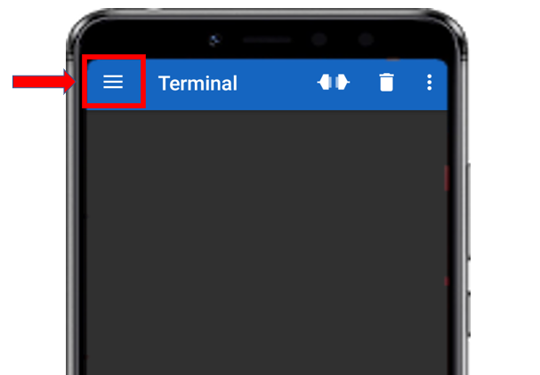
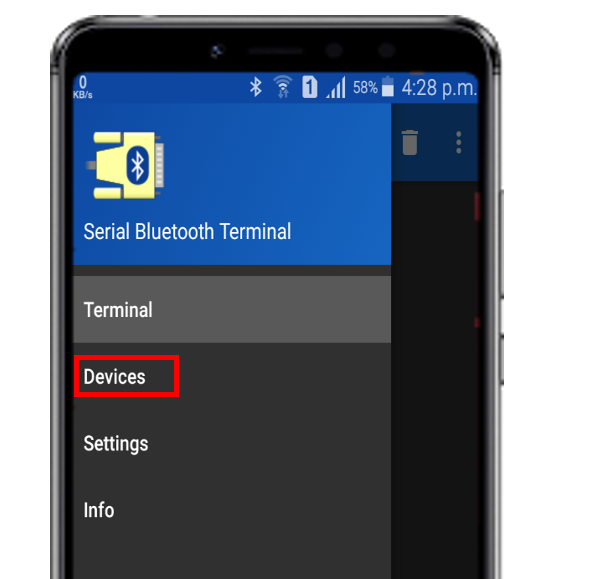
In your smartphone settings, enable Bluetooth. After you have installed the ‘Serial Bluetooth Terminal app, open it. On the top left corner of the screen, you will find three horizontal bars. Tap it.
Now, tap on the Devices tab.
In the ‘available devices’ section, select ‘ESP32test.’
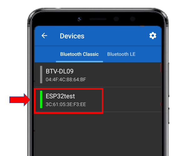
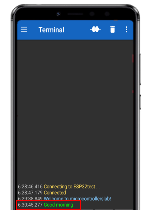
After you have selected your ESP32 module then tap the ‘link’ icon at the top of the screen. At first, you will get the message: ‘Connecting to ESP32test.’ After a successful connection, you will get the message: ‘Connected.’

For testing purposes, type a message in the app such as ‘Welcome to microcontrollerslab!’
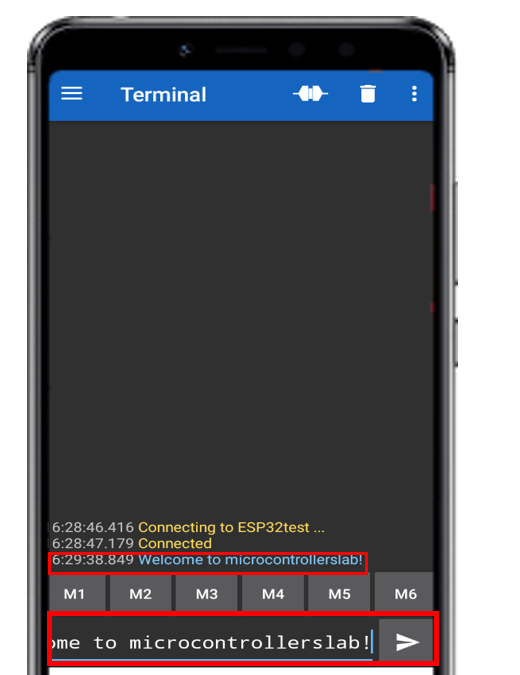
This message will be received instantly and will be displayed on the serial monitor on your Arduino IDE.
Similarly, we can also send a message on our serial monitor in the IDE. This will then be displayed on the serial Bluetooth app on the smartphone. On the serial monitor bar type, ‘Good morning’ and click the send button.

At the same time, you will receive this message on your smartphone app.
Send DS18B20 Readings and Control LED with Android App and ESP32
As we have seen how to establish two-way communication between our ESP32 module and our smartphone let us proceed a bit further and make our project more practical. We will achieve the following outputs through this project.
- Transmit sensor readings from the DS18B20 temperature sensor from the ESP32 development board to our smartphone.
- Use the serial Bluetooth terminal app in our smartphone to send a message of LED_ON and LED_OFF to turn a led on/off which will be connected to the ESP32 development board.
We will require the following components:
Required Components
- ESP32 development board
- Bluetooth enabled android smartphone
- One DS18b20 temperature sensor
- One 5mm LED
- One 220-ohm resistor
- One 4.5k-ohm resistor
- Breadboard
- Connecting Wires
Assemble the circuit as shown in the schematic diagram below:
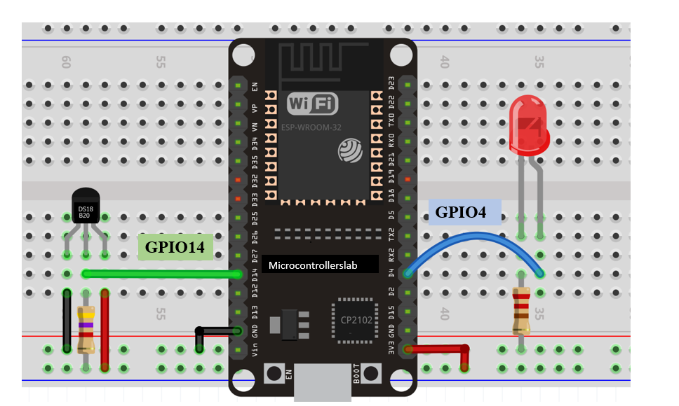
In the connection diagram above, we have connected the ds18b20 sensor’s middle terminal with GPIO14 through the 4.5k ohm resistor. The other terminals are powered by 3.3V and ground respectively. The 5mm LED’s anode is connected with GPIO4. The cathode is connected with 3.3V through the 220-ohm resistor.
Installing One Wire Library and Dallas Temperature Library
To use ds18b20 temperature sensor in Arduino IDE we will download two libraries by following the steps below.
- To install One wire library for free, click here. You will download the library as a .zip folder. Then you will extract it and rename it as ‘OneWire.’ Then, transfer this folder to the installation library folder in your Arduino IDE.
- To install Dallas Temperature library for free, click here. You will download the library as a .zip folder. Then you will extract it and rename as ‘DallasTemperature.’ Then, transfer this folder to the installation library folder in your Arduino IDE.
Alternatively, you can also go to your Arduino IDE and click Sketch > Include Library > Add .ZIP Library to include the two libraries individually. After installation of the libraries, restart your IDE.
ESP32 Code
Open the SerialtoSerialBT sketch we discussed above and make the following changes as shown below to incorporate the ds12b20 sensor and LED.
#include "BluetoothSerial.h"
#include <OneWire.h>
#include <DallasTemperature.h>

// Check if Bluetooth configs are enabled
#if !defined(CONFIG_BT_ENABLED) || !defined(CONFIG_BLUEDROID_ENABLED)
#error Bluetooth is not enabled! Please run `make menuconfig` to and enable it
#endif

// Bluetooth Serial object
BluetoothSerial SerialBT;


const int led = 4;  //LED is connected to GPIO4
const int temp_sensor = 14;     //ds18b20 is connected to GPIO14

OneWire oneWire(temp_sensor); //oneWire object created
DallasTemperature sensors(&oneWire);


String message = "";
char incomingChar;
String temperature = "";


unsigned long previousMillis = 0;    // Stores last time temperature was published
const long interval = 20000;

void setup() {
  pinMode(led, OUTPUT);
  Serial.begin(115200);
  SerialBT.begin("ESP32");
  Serial.println("Start pairing!");
}

void loop() {
  unsigned long currentMillis = millis();
  // Send temperature readings
  if (currentMillis - previousMillis >= interval){
    previousMillis = currentMillis;
    sensors.requestTemperatures();
    temperature = String(sensors.getTempCByIndex(0)) + "C  " +  String(sensors.getTempFByIndex(0)) + "F";
    SerialBT.println(temperature);
  }

  if (SerialBT.available()){
    char incomingChar = SerialBT.read();
    if (incomingChar != '\n'){
      message += String(incomingChar);
    }
    else{
      message = "";
    }
    Serial.write(incomingChar);
  }

  if (message =="led_ON"){
    digitalWrite(led, HIGH);
  }
  else if (message =="led_OFF"){
    digitalWrite(led, LOW);
  }
  delay(20);
}
How does the Code work?
Firstly, we will include the OneWire and DallasTemperature libraries that we download previously. These will be used to access the functions of the ds18b20 temperature sensor. The BluetoothSerial library will help in serial communication through Bluetooth.
#include "BluetoothSerial.h"
#include <OneWire.h>
#include <DallasTemperature.h>
Creating Object of BluetoothSerial Library
Then, create an object named SerialBT of the BluetoothSerial library. We will access the functionalities of two-way communication via this object.
BluetoothSerial SerialBT;Defining outputs variables
We will create two variables to define the GPIO pins through which the LED named led and the temperature sensor named ‘temp_sensor’ will be connected. The led will be connected with GPIO4 and the temp_sensor (ds18b20) will be connected with GPIO14.
const int led = 4;  //LED is connected to GPIO4
const int temp_sensor = 14;     //ds18b20 is connected to GPIO14
Creating instance
Then, we will create an instance of oneWire. We will use its reference as a parameter for the DallasTemperature function.
OneWire oneWire(temp_sensor);
DallasTemperature sensors(&oneWire);
Saving Data
By using the string data type, we will create a variable named message. This will hold a series of letters or numbers. The char data type will store the letters which we will receive through the Bluetooth connection. These will be stored in the ‘incomingChar’ variable. Also, the temperature variable of the type string will store the sensor readings which we will obtain.
String message = "";
char incomingChar;
String temperature = "";
Setting Time Interval
The timer interval will be set at 20000 milliseconds. Thus, after every 20 seconds, we will receive a new set of temperature readings.
unsigned long previousMillis = 0;   // Stores last time temperature was published
const long interval = 20000;        // interval at which to publish sensor readings
Setup()
Inside, the void setup() function, we will start the serial communication with a baud rate of 115200. By using the pinMode() function, we will specify the ‘led’ as the output pin. This is done because we have to turn the led on and off through the Bluetooth signal.
Then we will initialize our Bluetooth device’s name. It is named ‘ESP32.’ When the smartphone will try to pair with our device, this is the name which will be visible to it.
void setup() {
  pinMode(led, OUTPUT);    //Specifying led as output
  Serial.begin(115200);
  SerialBT.begin("ESP32");
  Serial.println("Start pairing!");
}
loop()
In the void loop() function we will perform the major operations of transmission and reception of data.
This block of code will look over the time passed since the last reading was sent. We had set the time interval as 20 seconds previously. If the 20 seconds have passed then the new temperature reading will get saved in the temperature variable. This reading will be both in Celsius and Fahrenheit SI units.
unsigned long currentMillis = millis();
if (currentMillis - previousMillis >= interval) {
    previousMillis = currentMillis;
    sensors.requestTemperatures();
    temperature = " " + String(sensors.getTempCByIndex(0)) + "C  " +  String(sensors.getTempFByIndex(0)) + "F";
Now, we will have to send the ‘temperature’ readings through the Bluetooth connection. Hence, we will use SerialBT.print() and pass the ‘temperature’ as the parameter inside it.
SerialBT.println(temperature); We will use a series of if statements to ensure the proper transmission of data. The first if statement will check if there is any message available in the Bluetooth serial port. Then we check to see whether the particular message that was present in the serial port is complete or not. This will be done by checking if the incomingChar is /n or not as “/n” indicates the end of a sentence. If /n is not detected then the previous characters are concatenated together to form a sentence.
if (SerialBT.available()) {

char incomingChar = SerialBT.read();
if (incomingChar!= '\n'){
  message += String(incomingChar);
}
After one message is read successfully, we clear the variable ‘message’ or else all further characters will get compiled together.
message = "";LED ON/OFF mechanism
Now, we will check for the content of the message. As we want to turn our LED on whenever a message of led_ON is detected and turn it off whenever ‘led_OFF’ message is detected.
This will be achieved by using the digitalWrite() function. This function takes in two parameters. The first parameter is the GPIO pin which is connected to our LED and the second parameter denotes whether we want to turn that pin HIGH or LOW. High means passing a logic signal 1 so the LED turns ON and low means passing a logic signal 0 so the LED turns OFF.
if (message =="led_ON"){
   digitalWrite(led, HIGH);
}

else if (message =="led_OFF"){
  digitalWrite(led, LOW);
}
Demonstration
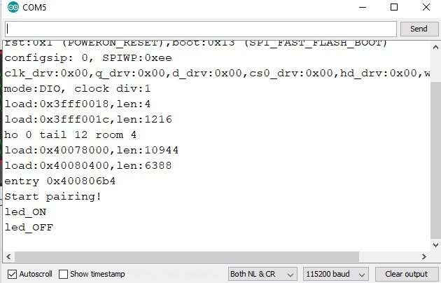
Upload the code given above to your ESP32 module and press the ENABLE button. In your serial monitor, the following message will be displayed: ‘Start pairing!’
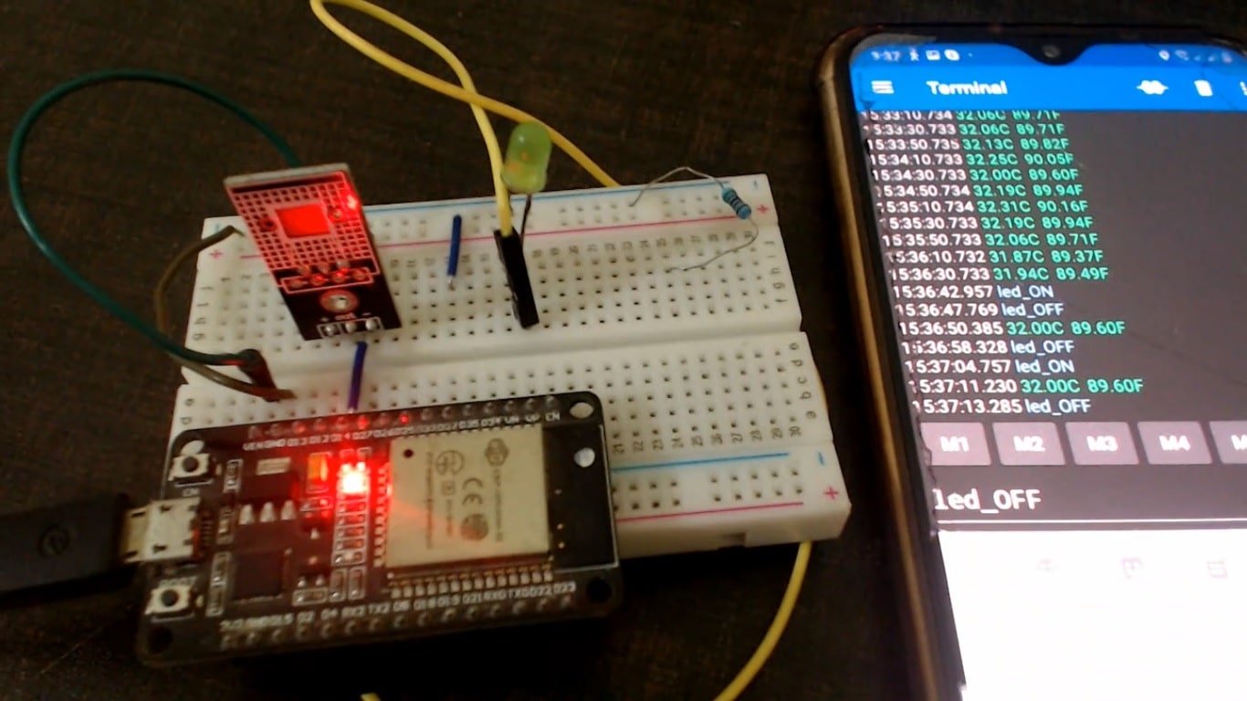
Now, you will be able to connect both the smartphone and the ESP32 module through Bluetooth. After you have paired your devices go to the serial terminal app and write LED_ON and LED_OFF to control the GPIO pins of ESP32.
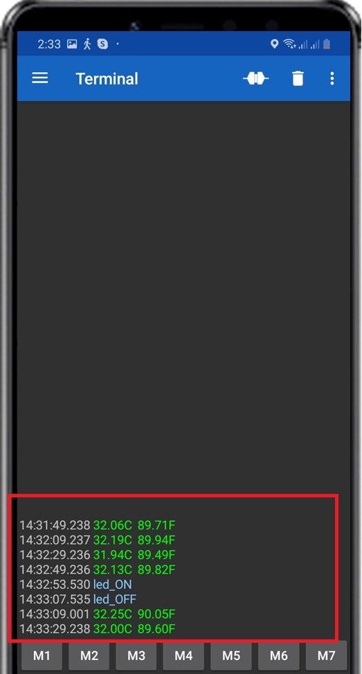
In the serial monitor of your Arduino IDE, you will be able to view data received from an Android app to control an LED.
Video Demo
Conclusion
In summary, we learned how to establish two-way communication with ESP32 and Android via Bluetooth Classic using Arduino IDE.
Related Bluetooth tutorials and projects:
- HC-05 Bluetooth Interfacing with TM4C123G Tiva C Launchpad – Keil uvision
- HC06 Bluetooth Module Guide with Arduino Interfacing
- HM-10 Bluetooth Module – Interfacing Example with Arduino
- Introduction to Bluetooth Low Energy
- Control 2 DC Motors via Bluetooth and Arduino
- Bluetooth Based Home Automation project using Arduino
- HC-05 Bluetooth module interfacing with arduino with LED control example
- Bluetooth module HC 05 interfacing with pic microcontroller
dear sir,
I am so thanks fully to you. I respact to you . you shear his knowleg. I am so proud of you.
I know that 2 years have passed since the publication of the article, but I have a question: how can you connect ESP32 via classic Bluetooth with a smartphone that has Android 12 or 13? With Android 11 or older it works perfectly but with 12 it only pairs but does not connect.