In this tutorial, we will learn about the 28BYJ-48 stepper motor and how to interface it with Raspberry Pi Pico using a ULN2003 driver. The 28BYJ-48 stepper motor is one of the most inexpensive and widely used stepper motors available today. It comes with a ULN2003 motor driver board that is responsible for driving the stepper motor. The Raspberry Pi Pico GPIO pins cannot provide enough driving current for the 28BYJ-48 stepper motor, so a dedicated driver is essential. The driver also protects the board’s GPIO pins from damage caused by the high current demands of the stepper motor.
We have a similar guide using MicroPython for ESP32:
Recommended Components
The following components are used in this project or are helpful for getting started with Raspberry Pi Pico development.
| Component | How it’s used in this project | Buy on Amazon |
|---|---|---|
| Raspberry Pi Pico | The RP2040 microcontroller board used in this tutorial. | Check Price |
| 28BYJ-48 Stepper + ULN2003 | 28BYJ-48 stepper motor with ULN2003 driver board. | Check Price |
| Breadboard | Solderless breadboard for building the circuit. | Check Price |
| Jumper Wires | Male-to-male / male-to-female wires for the connections. | Check Price |
As an Amazon Associate we earn from qualifying purchases. Prices and availability are accurate as of the date/time indicated and are subject to change.
Prerequisites
Before starting this tutorial, make sure you have the latest version of Python 3 installed on your system and MicroPython set up on your Raspberry Pi Pico. You will also need a working IDE for programming. We will be using Thonny IDE throughout this guide.
If you are using uPyCraft IDE, you can check this getting started guide:
Required Components
- Raspberry Pi Pico board
- One 28BYJ-48 Stepper Motor with ULN2003 motor driver
- External 5V power supply
- Connecting wires
Stepper Motors Introduction
Stepper motors are DC brushless and synchronous motors. They rotate in discrete steps of predefined angles and can rotate both clockwise and counterclockwise. Unlike standard DC motors, stepper motors offer precise positional control based on the number of steps per revolution. A complete revolution of a stepper motor is divided into a fixed number of discrete steps. This makes them ideal for applications that require accurate positioning, such as CNC machines, robotics, 3D printers, and camera sliders.
Stepper motors do not need feedback sensors for positional control under most conditions. Each input pulse moves the shaft by one step, allowing you to track position by counting steps in software. This open-loop control capability makes them simple and cost-effective for many automation projects.
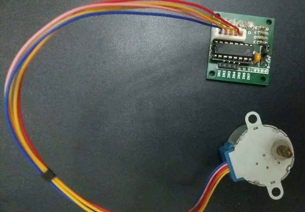
For this guide, we will use a 28BYJ-48 stepper motor controlled through the ULN2003 motor driver.
28BYJ-48 Stepper Motor
The 28BYJ-48 is the most commonly used stepper motor in hobbyist and low-power industrial projects. It is compact, inexpensive, and very easy to control with a microcontroller.
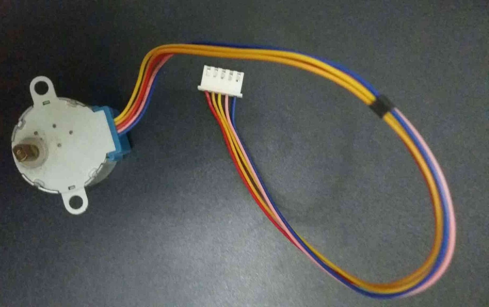
The 28BYJ-48 is a unipolar 5V stepper motor that converts electrical signals into mechanical rotation. It consists of 4 stationary coils (the stator) rated at +5V arranged around the rotor. Because of its 5V operating voltage, you can easily drive this motor using microcontrollers like the Raspberry Pi Pico, ESP32, ESP8266, Arduino, or TM4C123 Tiva Launchpad. It has a 1/64 reduction gear set and moves in precise half steps, resulting in 512 steps per revolution. These motors are quiet compared to other DC motors and servo motors, and you can achieve reliable positional control without additional feedback circuitry.
Stride Angle
The 28BYJ-48 has a stride angle of 5.625 degrees in half-step mode. That means it completes one revolution in 64 steps (360 / 5.625 = 64), with each step covering 5.625 degrees. In full-step mode, the stride angle doubles to 11.25 degrees, and the motor completes one revolution in just 32 steps. The half-step method is generally recommended because it provides smoother rotation and better positional accuracy than full-step mode.
In order to move one step forward or backward, the coils of the motor must be energized in a specific sequence. Changing the order of this sequence reverses the direction of rotation.
Steps per Revolution & Step Angle
The output shaft of the 28BYJ-48 is driven through an internal gear ratio of 64:1, also known as the speed variation ratio. This means the internal motor must rotate 64 times for the output shaft to complete one full rotation.
From this we can conclude:
- One full shaft rotation requires a total of 2048 steps (32 steps per internal revolution × 64 gear ratio = 2048).
- This gives the motor a step angle of 360° / 2048 = 0.18° per step, enabling very fine positional control.
Specifications
- Unipolar motor with 5 pins and a rated DC voltage of 5V
- 4 phases with a stride angle of 5.625°/64
- Speed variation ratio: 1/64
- Operating frequency: 100 Hz
- Insulated power: 600VAC / 1mA / 1s
- Half-step drive method is recommended
- Pull-in torque: 300 gf·cm
- Current consumption: approximately 240mA
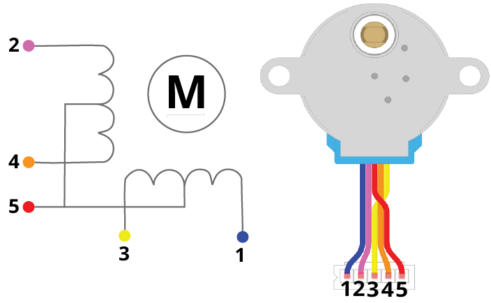
Pinout
The 28BYJ-48 has a 5-pin connector. Four of these pins connect to the individual stator coils, and one pin is the +5V supply. The table below describes each pin:
Pin Configuration Details
| Pin Number | Coil Number | Colour |
| 1 | 4 | Blue |
| 2 | 2 | Pink |
| 3 | 3 | Yellow |
| 4 | 1 | Orange |
| 5 | Vcc | Red |
Coil 1 to Coil 4: These coils control the step sequence of the stepper motor. One end of each coil connects to +5V, while the other end connects to a ULN2003 driver output. Activating the coils in the correct sequence causes the rotor to step forward or backward.
Vcc: Supplies +5V to the stepper motor. This voltage appears across each coil when the corresponding coil is grounded through the driver IC.
ULN2003 Stepper Motor Driver Module
To drive the 28BYJ-48 stepper motor with Raspberry Pi Pico, you must use the ULN2003 motor driver. The reason is that the 28BYJ-48 consumes approximately 240mA during operation, which is far beyond the ~4mA that a single Raspberry Pi Pico GPIO pin can safely source. The ULN2003 translates the low-current GPIO output signals from the Pico into the higher current levels required to energize the stepper motor coils.
The ULN2003 breakout board contains high-voltage, high-current Darlington transistor arrays. Each channel can independently drive up to 500mA at 50V, making it ideal for inductive loads like stepper motor coils. The board also includes freewheeling diodes on each output to suppress voltage spikes generated when the coil current is switched off — this protects both the driver IC and the microcontroller.
Recommended reading: ULN2003 introduction, pinout, example and features
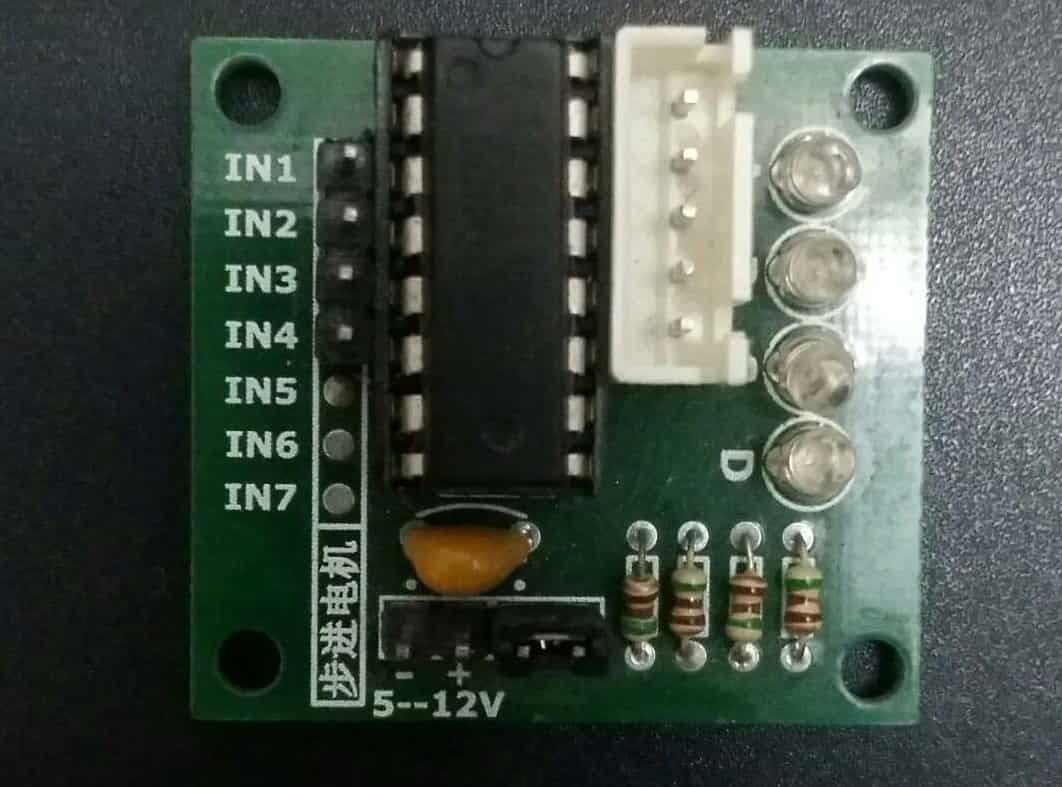
Stepper Motor Driver Module Pinout
The ULN2003 driver IC contains 7 Darlington pair transistor outputs. Each output can drive a 500mA, 50V load. To control the 28BYJ-48, only four of the seven channels are used (IN1 through IN4). The input signals from the Raspberry Pi Pico GPIO pins go directly into these four input channels.
The following diagram shows the ULN2003 motor driver board:
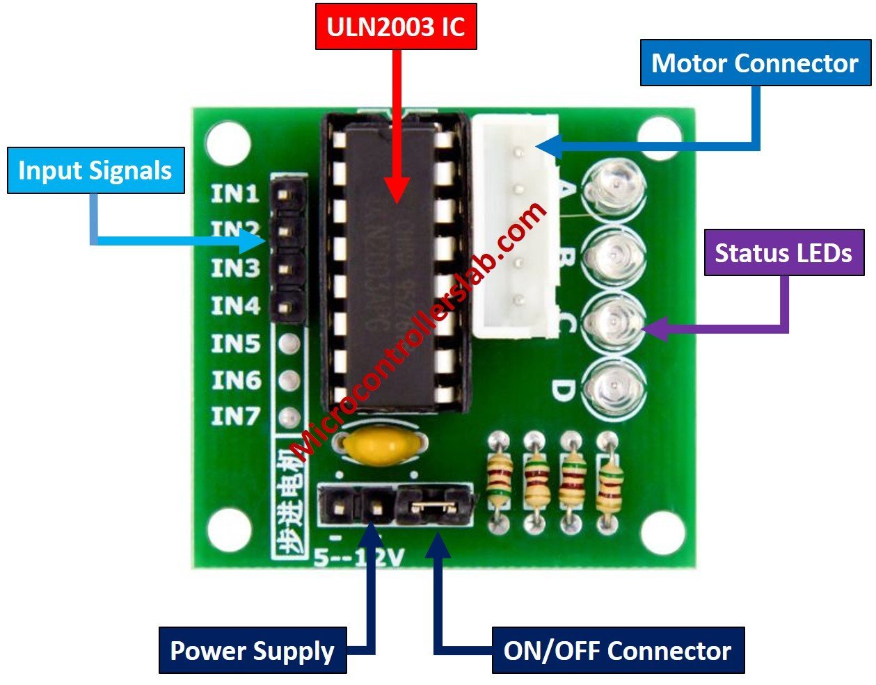
The motor connector header plugs directly into the 5-pin connector of the 28BYJ-48 stepper motor. This provides the four controlled ground paths for each coil.
| Pin | Description |
| IN1 to IN4 | Input pins that receive control signals from the Raspberry Pi Pico GPIO pins. These signals define the coil energization sequence. |
| Vcc and GND | Power supply pins. Connect Vcc to an external 5V supply and GND to the common ground shared with the Pico. |
Important: The 28BYJ-48 stepper motor draws approximately 240mA and also consumes power when idle. Do not power it directly from the Raspberry Pi Pico’s 3.3V or 5V pins. Always use a dedicated external 5V power supply to avoid damaging your Pico board.
Interfacing Raspberry Pi Pico with 28BYJ-48 Stepper Motor and ULN2003 Motor Driver
To connect Raspberry Pi Pico with the stepper motor and driver, we use the driver’s IN1–IN4 input pins, the power supply pins, and the motor connector header. The 28BYJ-48 stepper motor plugs directly into the driver board via its 5-pin connector. We then connect four GPIO pins of the Raspberry Pi Pico to the IN1–IN4 inputs of the driver board. The pin mapping used in this tutorial is shown below:
| Raspberry Pi Pico | Motor Driver |
|---|---|
| GP2 | IN1 |
| GP3 | IN2 |
| GP4 | IN3 |
| GP5 | IN4 |
You may use any other available GPIO pins on the Raspberry Pi Pico as long as you update the pin numbers in the MicroPython script accordingly.
Power the ULN2003 driver board using an external 5V power supply. Connect the GND of the external power supply to the GND pin of the Raspberry Pi Pico to establish a common ground reference. Without a common ground, the logic signals from the Pico will not be interpreted correctly by the driver.
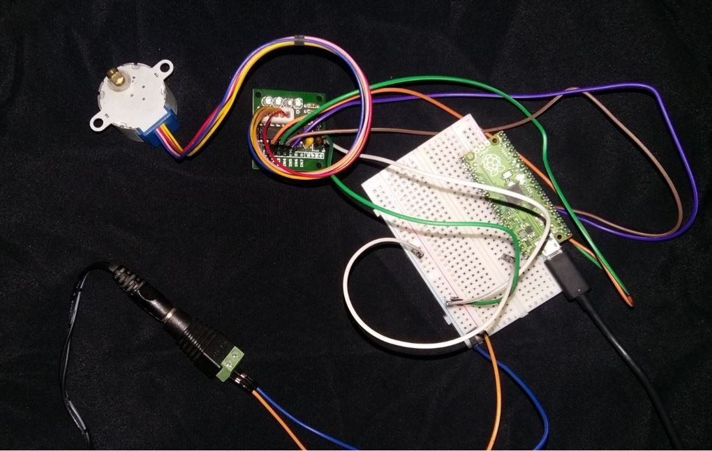
The wiring diagram is shown below:

MicroPython Script: 28BYJ-48 Stepper Motor with Raspberry Pi Pico
The MicroPython script below rotates the stepper motor in the clockwise direction. To achieve this, we provide a sequence of high (1) and low (0) values to the four stepper motor control pins in a repeating pattern. Each pattern in the sequence energizes a different combination of coils, causing the rotor to advance by one step.
from machine import Pin
from time import sleep

IN1 = Pin(2, Pin.OUT)
IN2 = Pin(3, Pin.OUT)
IN3 = Pin(4, Pin.OUT)
IN4 = Pin(5, Pin.OUT)

pins = [IN1, IN2, IN3, IN4]

sequence = [[1,0,0,0],[0,1,0,0],[0,0,1,0],[0,0,0,1]]

while True:
    for step in sequence:
        for i in range(len(pins)):
            pins[i].value(step[i])
            sleep(0.001)
How the Code Works
Let us go through the code step by step to understand how it controls the stepper motor.
Importing Libraries
We start by importing the Pin class from the machine module and the sleep function from the time module. The machine module gives us access to the hardware peripherals of the Raspberry Pi Pico, including GPIO pins. The sleep function allows us to insert small delays between steps, which is necessary for smooth and reliable motor movement.
from machine import Pin
from time import sleep
Configuring GPIO Pins
Next, we configure GP2, GP3, GP4, and GP5 as digital output pins using the Pin() constructor. The first argument is the GPIO number, and the second argument Pin.OUT sets the pin direction as output. We then store all four pin objects in a list called pins for easy iteration.
IN1 = Pin(2, Pin.OUT)
IN2 = Pin(3, Pin.OUT)
IN3 = Pin(4, Pin.OUT)
IN4 = Pin(5, Pin.OUT)

pins = [IN1, IN2, IN3, IN4]
Defining the Step Sequence
The sequence is a 2D list that defines the pattern of high and low signals sent to the four coil pins. This is a full-step sequence where only one coil is energized at a time. Each row in the list represents one step.
sequence = [[1,0,0,0],[0,1,0,0],[0,0,1,0],[0,0,0,1]]To rotate the motor in the counterclockwise direction, simply reverse the sequence list:
sequence = [[0,0,0,1],[0,0,1,0],[0,1,0,0],[1,0,0,0]]Main Loop
The while True loop runs the motor continuously. For each step in the sequence, we iterate through all four pins and apply the corresponding high or low value. A 1ms delay (sleep(0.001)) is inserted after each pin update to ensure stable switching. Reducing this delay speeds up the motor, while increasing it slows it down. If the delay is too small, the motor may skip steps or stall due to insufficient time for the coils to energize.
while True:
    for step in sequence:
        for i in range(len(pins)):
            pins[i].value(step[i])
            sleep(0.001)
Controlling the Number of Steps and Rotations
In many real-world applications, you may want to rotate the motor by a specific number of degrees or complete a set number of full rotations rather than spinning indefinitely. Since each complete cycle through the 4-step sequence moves the motor 4 steps, and we need 2048 steps for one full shaft rotation, you can use the following approach:
from machine import Pin
from time import sleep

IN1 = Pin(2, Pin.OUT)
IN2 = Pin(3, Pin.OUT)
IN3 = Pin(4, Pin.OUT)
IN4 = Pin(5, Pin.OUT)

pins = [IN1, IN2, IN3, IN4]

# Full-step sequence (clockwise)
sequence = [[1,0,0,0],[0,1,0,0],[0,0,1,0],[0,0,0,1]]

def rotate_steps(steps):
    for _ in range(steps):
        for step in sequence:
            for i in range(len(pins)):
                pins[i].value(step[i])
            sleep(0.002)

# Rotate 1 full revolution (2048 steps)
rotate_steps(2048)

# Stop motor by de-energizing all coils
for pin in pins:
    pin.value(0)
This function is much more practical for applications like valve control, conveyor belts, or any mechanism where you need to move to a specific position and stop.
Troubleshooting Tips
If you encounter issues while running this project, here are some common problems and their solutions:
- Motor not moving at all: Check that your external 5V power supply is properly connected to the ULN2003 driver’s Vcc pin. Also verify that the GND of the power supply is connected to the GND of the Raspberry Pi Pico.
- Motor vibrating but not rotating: This usually indicates incorrect wiring or a wrong step sequence. Verify that IN1–IN4 on the driver match the GPIO pin assignments in your code.
- Motor getting hot quickly: De-energize the coils when the motor is not moving by setting all pins to 0. Leaving the coils energized while stationary wastes power and generates unnecessary heat.
- Motor losing steps or stalling: The step delay may be too short. Try increasing
sleep(0.001)tosleep(0.002)or higher. Running under a heavy mechanical load can also cause stalling. - Erratic behavior: Ensure the motor’s 5-pin connector is securely seated in the ULN2003 board’s connector. A loose connection can cause unpredictable behavior.
Practical Applications
The 28BYJ-48 stepper motor combined with the Raspberry Pi Pico is suitable for a wide range of hobbyist and educational projects, including:
- Pan and tilt camera platforms: Use two stepper motors to precisely position a camera in two axes for time-lapse photography or surveillance.
- Automated blinds or curtains: Control the opening and closing of window blinds with exact step counting for precise positioning.
- Robot joints: Drive low-torque robot arm joints where precise angular movement is needed.
- Conveyor mechanisms: Move objects by a specific distance in a production or sorting system.
- Miniature CNC plotters: Build a small drawing machine or plotter using two stepper motors for X and Y axis movement.
- Smart locks and valves: Rotate a mechanism to a specific locked or unlocked position using step counting.
Demonstration
To test the code, copy the main script into Thonny IDE and upload it to your Raspberry Pi Pico. Connect the stepper motor and ULN2003 driver to the Pico according to the wiring diagram above. When you run the script, the stepper motor will begin rotating in the clockwise direction continuously.
You may also like to read about other motor types with Raspberry Pi Pico:
- Servo Motor with Raspberry Pi Pico using MicroPython
- Control DC Motor using L298N Driver with Raspberry Pi Pico and MicroPython
Related tutorials and projects:
- Stepper Motor Interfacing with TM4C123 Tiva Launchpad
- Stepper Motor Control with L293D Motor Driver IC and Arduino
- 28BYJ-48 5 Volt Stepper Motor Guide
- NEMA 23 Stepper Motor Pinout, Features and Example with Arduino
- Stepper Motor Interfacing with 8051 Microcontroller
- TMC2209 Stepper Motor Driver Module – SilentStepStick
- NEMA 34 Stepper Motor
- Stepper Motor Interfacing with PIC16F877A Microcontroller
Nice one!
I’m beginning to experiment with pico and it was easy to setup my motor with your help, thanks!
I now would like to add a push button to start/stop the motor, any ideia on how to do it?