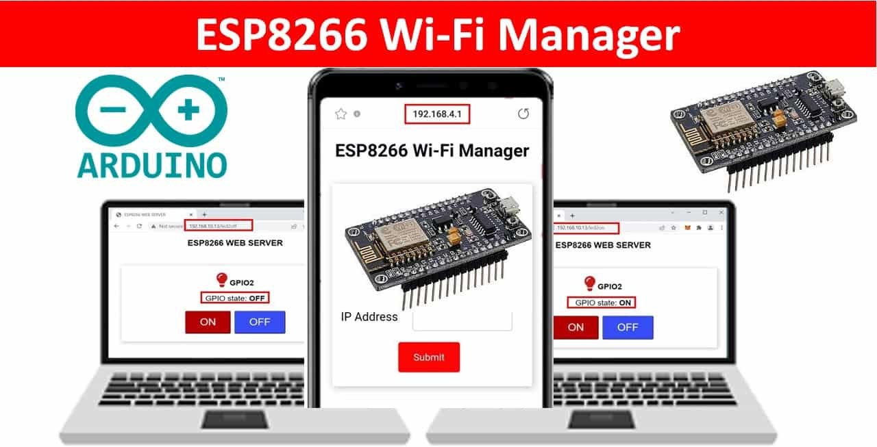
In this user guide, we will learn how to incorporate WiFi manager with ESP8266 Web Server projects using an ESPAsyncWebServer library. WiFi manager allows us to connect ESP8266 to a network without having to hardcode our network credentials in an Arduino sketch. We will be using a previous example when we learned how to build a web server (ESP8266 NodeMCU Web Server using LittleFS (Flash File System)) and include the WiFimanager in it for better functionality. That ESP8266 Web server revolved around the working of LittleFS, where we created and stored individual HTML and CSS files through which we built a web server that controlled the onboard LED of the ESP8266 module. This time we will take it a step ahead and incorporate WiFi manager with it. So let us begin.
We have a similar guide for ESP32/ESP8266 WiFi Manager in MicroPython as well. You may want to have a look:
- MicroPython: WiFi Manager with ESP32 and ESP8266
- Create a Wi-Fi Manager for ESP32 using AsyncWebServer library
ESP8266 NodeMCU WiFi Manager Introduction
With the addition of the WiFi manager with the ESPAsyncWebServer library, we no longer have to separately provide the SSID and password of the local network in our Arduino sketch. No hard coding would be required. We will be able to connect through other networks (Access Points) with our ESP8266 boards automatically without any hassle of manually entering the network credentials every time. Multiple SSID connections, as well as additional custom variables, can also be implemented through this.
Working Process
- Initially, our ESP8266 will be set up as an Access Point when it starts. This is because the ESP8266 board starts with reading the ssid.txt, pass.txt, and ip.txt files. These will be empty at present.
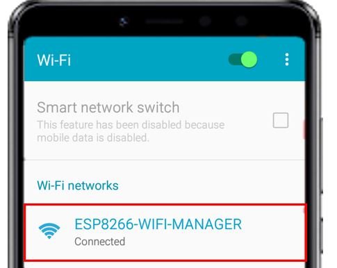
- Next, to connect to our ESP8266 board which acts as an AP we will connect to “ESP8266-WiFi-Manager” on our smartphone. At this point, the access point will be set.
- We will go to the IP address 192.168.4.1. The ESP8266 WiFi manager web page will open up. Here we will provide the SSID, the password, and an available IP address to connect to. They will get saved in their respective files: ssid.txt, pass.txt, and ip.txt. These settings will get configured once we press the ‘Submit’ button.
- These network credentials of the network we chose, will get saved in our ESP8266.
- The ESP8266 will restart and now will be able to connect with the network we selected because the files now contain the parameters needed to connect to station mode. In this phase, the ESP8266 board now acts in the Station mode.
- Now we will enter the IP address that we just set in a new web page and the ESP8266 Control GPIO Outputs Webserver will open up. This will allow us to control the onboard LED of our ESP8266 board by clicking the two ON and OFF buttons.
- If however the connection was not successfully established, then the ESP8266 board again goes in AP mode and the user will have to input the network parameters again on the ESP8266 WiFi Manager web page accessed at IP address 192.168.4.1.
This WiFi manager can be set up with any relevant ESP8266 Web server projects that we have created. For simplicity purposes, we have chosen a web server that controls a single GPIO output.
Setting up Arduino IDE
To follow this LittleFS-based WiFi manager web server project, make sure you have the latest version of Arduino IDE and the ESP8266 add-on installed on your Arduino IDE. If you have not installed it before you can follow this tutorial:
Install ESP8266 in Arduino IDE ( Windows, Linux, and Mac OS)
Also, you will have to download and install the ESP8266 NodeMCU Filesystem Uploader Plugin in your Arduino IDE so that you are able to upload the LittleFS files on your ESP8266 NodeMCU board. If you haven’t, you can follow this tutorial:
LittleFS Introduction & Install ESP8266 NodeMCU Filesystem Uploader in Arduino IDE
Installing ESPAsyncWebServer Library and ESPAsyncTCP Library
We will need two additional libraries to build our web server. The ESPAsyncWebServer library will help us in creating our web server easily. With this library, we will set up an asynchronous HTTP server. ESPAsyncTCP is another library that we will be incorporating as it a dependency for the ESPAsyncWebServer library. Both of these libraries are not available in the Arduino library manager so we will have to download and load them in our ESP8266 NodeMCU board ourselves.
- To install the ESPAsyncWebServer library for free, click here to download. You will download the library as a .zip folder which you will extract and rename as ‘ESPAsyncWebServer.’ Then, transfer this folder to the installation library folder in your Arduino IDE.
- To install the ESPAsyncTCP library for free, click here to download. You will download the library as a .zip folder which you will extract and rename as ‘ESPAsyncTCP.’ Then, transfer this folder to the installation library folder in your Arduino IDE.
Likewise, you can also go to Sketch > Include Library > Add .zip Library inside the IDE to add the libraries as well. After installation of the libraries, restart your IDE.
You can read about asynchronous web server here:
- ESP32 Asynchronous Web Server using Arduino IDE and ESPAsyncWebServer library
- ESP8266 NodeMCU Asynchronous Web Server using Arduino IDE and ESPAsyncWebServer library
Creating Files for LittleFS
To build our ESP8266 WiFi manager web server using LittleFS, we will create four different files: two HTML files (index.html for the web page that will control the onboard LED and wifimanager.html for the WiFi manager web page when our ESP8266 will be in AP mode), CSS, and Arduino sketch and organize them in a project folder like shown below:
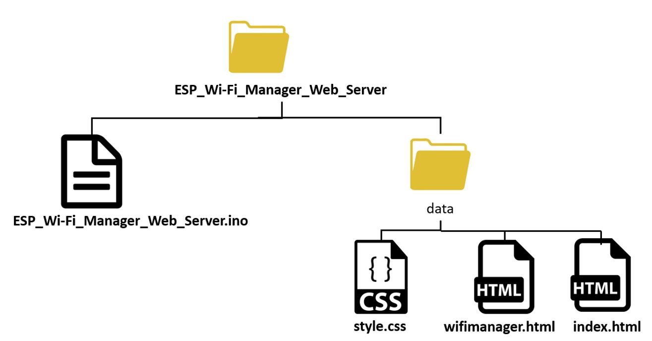
Note: You should place HTML and CSS files inside the data folder. Otherwise, the LittleFS library will not be able to read these files.
Creating HTML files
As mentioned before our project consists of two HTML files: index.html and wifimanager.html. One will be responsible for building the ESP8266 web server that controls the onboard LED and the other will be responsible for building the WiFi manager web page.
index.html
Inside our index.html file, we will include the title, a paragraph for the GPIO state, and two on/off buttons.
Now, create an index.html file and replicate the code given below in that file.
<!DOCTYPE html>
<html>

<head>
  <title>ESP8266 WEB SERVER</title>
  <meta name="viewport" content="width=device-width, initial-scale=1">
  <link rel="icon" href="data:,">
  <link rel="stylesheet" href="https://use.fontawesome.com/releases/v5.7.2/css/all.css"
    integrity="sha384-fnmOCqbTlWIlj8LyTjo7mOUStjsKC4pOpQbqyi7RrhN7udi9RwhKkMHpvLbHG9Sr" crossorigin="anonymous">
  <link rel="stylesheet" type="text/css" href="style.css">
</head>

<body>
  <h2>ESP8266 WEB SERVER</h2>
  <div class="content">
    <div class="card-grid">
      <div class="card">
        <p><i class="fas fa-lightbulb fa-2x" style="color:#c81919;"></i>     <strong>GPIO2</strong></p>
        <p>GPIO state: <strong> %GPIO_STATE%</strong></p>
        <p>
          <a href="/led2on"><button class="button">ON</button></a>
          <a href="/led2off"><button class="button button2">OFF</button></a>
        </p>
      </div>
    </div>
  </div>
</body>

</html>
To understand how this HTML file works go to our previous article here. You will find a detailed explanation of all the parts.
wifimanager.html
The WiFi manager web page consists of an asynchronous web server that will allow us to input data types of ‘string’ via input fields. Inside the web page, there will be a heading ‘ESP8266 WiFi Manager’. Underneath it, there will be three input fields for the user to enter and save the values and a ‘Submit’ button. The first input field will take in the SSID name, the second input field will take the password and the third one will take the IP address. After you click the submit button, the respective values will get saved in the variables that we will define in the Arduino program code.
<!DOCTYPE html>
<html>
<head>
  <title>ESP8266 Wi-Fi Manager</title>
  <meta name="viewport" content="width=device-width, initial-scale=1">
  <link rel="icon" href="data:,">
  <link rel="stylesheet" href="https://use.fontawesome.com/releases/v5.7.2/css/all.css" integrity="sha384-fnmOCqbTlWIlj8LyTjo7mOUStjsKC4pOpQbqyi7RrhN7udi9RwhKkMHpvLbHG9Sr" crossorigin="anonymous">
  <link rel="stylesheet" type="text/css" href="style.css">
</head>
<body>
    <h1>ESP8266 Wi-Fi Manager</h1>
  </div>
  <div class="content">
    <div class="card-grid">
      <div class="card">
        <form action="/" method="POST">
          <p>
            <label for="ssid">SSID</label>
            <input type="text" id ="ssid" name="ssid"><br>
            <label for="pass">Password</label>
            <input type="text" id ="pass" name="pass"><br>
            <label for="ip">IP Address</label>
            <input type="text" id ="ip" name="ip">
            <input type ="submit" value ="Submit">
          </p>
        </form>
      </div>
    </div>
  </div>
</body>
</html>
Underneath the heading, we will add the user inputs which need to be filled. This will be of the type ‘form.’ We will define its action as “/POST” which means an HTTP POST request will be sent when the user will input the fields and press the submit button. As we are displaying three input fields on our web page thus, we will define separate labels and ids for them. The first input box saves the value for “ssid” and is of type text. The second input box saves the value for “pass” and is also of type text. Lastly, the third input box saves the value for “ip” and is also of type text.
Basically we have three input fields each of type text which update their respective variables whenever a valid value is entered in the box and the submit button is pressed.
<form action="/" method="POST">
          <p>
            <label for="ssid">SSID</label>
            <input type="text" id ="ssid" name="ssid"><br>
            <label for="pass">Password</label>
            <input type="text" id ="pass" name="pass"><br>
            <label for="ip">IP Address</label>
            <input type="text" id ="ip" name="ip">
            <input type ="submit" value ="Submit">
          </p>
        </form>
We have a dedicated article where we discussed in depth how to build a web page with input fields. You can refer to the article from here: ESP32/ESP8266 Web Server with Input Data on HTML Form using Arduino IDE
Creating CSS File
Next, create another file “style.css” in the same folder as the HTML files and replicate the code given below in that file.
html {
  font-family: Arial, Helvetica, sans-serif;
  display: inline-block;
  text-align: center;
}

h1 {
  font-size: 1.8rem;
  color: #070812;

}

p {
  font-size: 1.4rem;
}

body {
  margin: 0;
}

.content {
  padding: 5%;
}

.card-grid {
  max-width: 800px;
  margin: 0 auto;
  display: grid;
  grid-gap: 2rem;
  grid-template-columns: repeat(auto-fit, minmax(300px, 1fr));
}

.card {
  background-color: white;
  box-shadow: 2px 2px 12px 1px rgba(140,140,140,.5);
}


input[type=submit] {
  border: none;
  color: #FEFCFB;
  background-color: #fa0505;
  padding: 15px 15px;
  text-align: center;
  text-decoration: none;
  display: inline-block;
  font-size: 16px;
  width: 100px;
  margin-right: 10px;
  border-radius: 4px;
  transition-duration: 0.4s;
  }


input[type=text], input[type=number], select {
  width: 50%;
  padding: 12px 20px;
  margin: 18px;
  display: inline-block;
  border: 1px solid #ccc;
  border-radius: 4px;
  box-sizing: border-box;
}

label {
  font-size: 1.2rem;
}
.value{
  font-size: 1.2rem;
  color: #1282A2;
}


.button {
  display: inline-block;
  background-color: #b30000; //red color
  border: none;
  border-radius: 4px;
  color: white;
  padding: 16px 40px;
  text-decoration: none;
  font-size: 30px;
  margin: 2px;
  cursor: pointer;
}
.button2 {
  background-color: #364cf4; //blue color
}
Inside our CSS file which will be used to give styles to our web page, we will specify the font types, size and colors of the headings, paragraphs and the buttons. We will set the display text to font type Arial and align it in the centre of the webpage.
To understand more about CSS styling refer to our previous ESP Web Server articles.
Arduino Sketch ESP8266 WiFi Manager Web Server
Finally, we will create a new file and save it as ESP_Wi-Fi_Manager_Web_Server. Copy the code given below in that file.
#include <Arduino.h>
#include <ESP8266WiFi.h>
#include <ESPAsyncTCP.h>
#include <ESPAsyncWebServer.h>
#include "LittleFS.h"

AsyncWebServer server(80);

const char* input_parameter1 = "ssid";
const char* input_parameter2 = "pass";
const char* input_parameter3 = "ip";

//Variables to save values from HTML form
String ssid;
String pass;
String ip;

// File paths to save input values permanently
const char* SSID_path = "/ssid.txt";
const char* Password_path = "/pass.txt";
const char* IP_path = "/ip.txt";

boolean restart = false;

IPAddress localIP;
IPAddress gateway(192, 168, 1, 1);
IPAddress subnet(255, 255, 0, 0);

unsigned long previous_time = 0;
const long Delay = 10000;

const int ledPin = 2;
String ledState;

// Read File from LittleFS
String readFile(fs::FS &fs, const char * path){
  Serial.printf("Reading file: %s\r\n", path);

  File file = fs.open(path,"r");
  if(!file || file.isDirectory()){
    Serial.println("- failed to open file for reading");
    return String();
  }

  String fileContent;
  while(file.available()){
    fileContent = file.readStringUntil('\n');
    break;
  }
  file.close();
  return fileContent;
}

// Write file to LittleFS
void writeFile(fs::FS &fs, const char * path, const char * message){
  Serial.printf("Writing file: %s\r\n", path);

  File file = fs.open(path,"w");
  if(!file){
    Serial.println("- failed to open file for writing");
    return;
  }
  if(file.print(message)){
    Serial.println("- file written");
  } else {
    Serial.println("- frite failed");
  }
}

// Initialize WiFi
bool initialize_Wifi() {
  if(ssid=="" || ip==""){
    Serial.println("Undefined SSID or IP address.");
    return false;
  }

  WiFi.mode(WIFI_STA);
  localIP.fromString(ip.c_str());

  if (!WiFi.config(localIP, gateway, subnet)){
    Serial.println("STA Failed to configure");
    return false;
  }
  WiFi.begin(ssid.c_str(), pass.c_str());
  Serial.println("Connecting to WiFi...");
  delay(20000);
  if(WiFi.status() != WL_CONNECTED) {
    Serial.println("Failed to connect.");
    return false;
  }

  Serial.println(WiFi.localIP());
  return true;
}

// Replaces placeholder with LED state value
String processor(const String& var) {
  if(var == "GPIO_STATE") {
    if(digitalRead(ledPin)) {
      ledState = "OFF";
    }
    else {
      ledState = "ON";
    }
    return ledState;
  }
  return String();
}

void setup() {
  Serial.begin(115200);

  if (!LittleFS.begin()) {
    Serial.println("An error has occurred while mounting LittleFS");
  }
  else{
   Serial.println("LittleFS mounted successfully");
  }

  pinMode(ledPin, OUTPUT);
  digitalWrite(ledPin, HIGH);  // Initially ESP8266 onboard LED OFF

  ssid = readFile(LittleFS, SSID_path);
  pass = readFile(LittleFS, Password_path);
  ip = readFile(LittleFS, IP_path);
  Serial.println(ssid);
  Serial.println(pass);
  Serial.println(ip);

  if(initialize_Wifi()) {
    server.on("/", HTTP_GET, [](AsyncWebServerRequest *request) {
      request->send(LittleFS, "/index.html", "text/html", false, processor);
    });
    server.serveStatic("/", LittleFS, "/");

    server.on("/led2on", HTTP_GET, [](AsyncWebServerRequest *request) {
      digitalWrite(ledPin, LOW);
      request->send(LittleFS, "/index.html", "text/html", false, processor);
    });

    server.on("/led2off", HTTP_GET, [](AsyncWebServerRequest *request) {
      digitalWrite(ledPin, HIGH);
      request->send(LittleFS, "/index.html", "text/html", false, processor);
    });
    server.begin();
  }
  else {
    Serial.println("Setting Access Point");
    WiFi.softAP("ESP8266-WIFI-MANAGER", NULL);

    IPAddress IP = WiFi.softAPIP();
    Serial.print("AP IP address: ");
    Serial.println(IP);

    // Web Server Root URL
    server.on("/", HTTP_GET, [](AsyncWebServerRequest *request){
      request->send(LittleFS, "/wifimanager.html", "text/html");
    });

    server.serveStatic("/", LittleFS, "/");

    server.on("/", HTTP_POST, [](AsyncWebServerRequest *request) {
      int params = request->params();
      for(int i=0;i<params;i++){
        AsyncWebParameter* p = request->getParam(i);
        if(p->isPost()){
          // HTTP POST ssid value
          if (p->name() == input_parameter1) {
            ssid = p->value().c_str();
            Serial.print("SSID set to: ");
            Serial.println(ssid);
            // Write file to save value
            writeFile(LittleFS, SSID_path, ssid.c_str());
          }
          // HTTP POST pass value
          if (p->name() == input_parameter2) {
            pass = p->value().c_str();
            Serial.print("Password set to: ");
            Serial.println(pass);
            // Write file to save value
            writeFile(LittleFS, Password_path, pass.c_str());
          }
          // HTTP POST ip value
          if (p->name() == input_parameter3) {
            ip = p->value().c_str();
            Serial.print("IP Address set to: ");
            Serial.println(ip);
            // Write file to save value
            writeFile(LittleFS, IP_path, ip.c_str());
          }
        }
      }
      restart = true;
      request->send(200, "text/plain", "Success. ESP8266 will now restart. Connect to your router and go to IP address: " + ip);
    });
    server.begin();
  }
}

void loop() {
   if (restart){
    delay(5000);
    ESP.restart();
  }


}
How the Code Works?
We will start by including the relevant libraries which are needed for this project. As we have to connect our ESP8266 to a wireless network, we need ESP8266WiFi.h library for that purpose. The ESPAsyncWebServer and ESPAsyncTCP libraries are the ones that we recently downloaded and will be required to build the asynchronous HTTP web server. Also, the LittleFS library will allow us to access the flash memory file system of our ESP8266 core.
#include <Arduino.h>
#include <ESP8266WiFi.h>
#include <ESPAsyncTCP.h>
#include <ESPAsyncWebServer.h>
#include "LittleFS.h"
The AsyncWebServer object will be used to set up the ESP8266 web server. We will pass the default HTTP port which is 80, as the input to the constructor. This will be the port where the server will listen to the incoming HTTP requests.
AsyncWebServer server(80);Defining Variables
Now, we will create three global variables for each input field. They will be used to monitor if an HTTP POST request was received from the input fields. If it was the case then the new updated values will get saved in each variable accordingly. The first is input_parameter1 with value ‘ssid’ saved. The second variable is input_parameter2 with value ‘pass’ saved. Lastly, the third one is input_parameter3 with value ‘ip’ saved. These variables will be updated whenever the user will enter a value in the respective input field and press the submit button on the WiFi manager web server.
const char* input_parameter1 = "ssid";
const char* input_parameter2 = "pass";
const char* input_parameter3 = "ip";
Next, we will define three string variables that will hold the values for the SSID, password, and the IP address entered by the user in the form.
String ssid;
String pass;
String ip;
The next three global variables will hold the paths for the SSID, password, and IP address .txt files in the ESP8266 filesystem.
const char* SSID_path = "/ssid.txt";
const char* Password_path = "/pass.txt";
const char* IP_path = "/ip.txt";
The following lines of code will define the gateway and subnet IP address.
IPAddress localIP;
IPAddress gateway(192, 168, 1, 1);
IPAddress subnet(255, 255, 0, 0);
Next, define the variable ledPin to give a symbolic name to the GPIO2 pin through which the onboard LED will be connected. The ledState variable will be used to store the current LED state which will be used later on in the program code.
const int ledPin = 2;
String ledState;
The following readFile() and writeFile() functions will be used to read and write the files to the LittleFS.
// Read File from LittleFS
String readFile(fs::FS &fs, const char * path){
  Serial.printf("Reading file: %s\r\n", path);

  File file = fs.open(path,"r");
  if(!file || file.isDirectory()){
    Serial.println("- failed to open file for reading");
    return String();
  }

  String fileContent;
  while(file.available()){
    fileContent = file.readStringUntil('\n');
    break;
  }
  file.close();
  return fileContent;
}

// Write file to LittleFS
void writeFile(fs::FS &fs, const char * path, const char * message){
  Serial.printf("Writing file: %s\r\n", path);

  File file = fs.open(path,"w");
  if(!file){
    Serial.println("- failed to open file for writing");
    return;
  }
  if(file.print(message)){
    Serial.println("- file written");
  } else {
    Serial.println("- frite failed");
  }
}
initialize_Wifi()
The following function will initialize the WiFi. It will set up the ESP8266 board in station mode and connect the board with the network credentials (ssid and pass) entered by the user on the form. This is achieved using the WiFi.begin() function and passing ssid.c_str() and pass.c_str() as parameters inside it. After the ESP8266 board successfully connects with the network parameters the IP address will get displayed in the Serial monitor. Notice that it will be the same IP address that the user will enter on the form. The initialize_Wifi() function will show whether the ESP8266 module was successfully able to connect with the network or not.
// Initialize WiFi
bool initialize_Wifi() {
  if(ssid=="" || ip==""){
    Serial.println("Undefined SSID or IP address.");
    return false;
  }

  WiFi.mode(WIFI_STA);
  localIP.fromString(ip.c_str());

  if (!WiFi.config(localIP, gateway, subnet)){
    Serial.println("STA Failed to configure");
    return false;
  }
  WiFi.begin(ssid.c_str(), pass.c_str());
  Serial.println("Connecting to WiFi...");
  delay(20000);
  if(WiFi.status() != WL_CONNECTED) {
    Serial.println("Failed to connect.");
    return false;
  }

  Serial.println(WiFi.localIP());
  return true;
}
processor()
Inside the processor() function, we will replace the placeholder %GPIO_STATE% with the LED state (1 or 0). The series of if-else statements will check whether the placeholder is indeed the one that we created in our HTML file. If it is, then it will check for the variable ledPin which specifies the GPIO2 connected to the onboard LED. If the state is 1(HIGH) then ledState variable will be saved as ‘OFF’ otherwise it will be saved as ‘ON.’ As a result, this variable will be returned and will replace GPIO_STATE with the ledState value.
Note: For ESP8266, the onboard LED works on an opposite logic as compared to ESP32. To turn the onboard LED ON, a low signal is sent, and to turn it OFF, a high signal is sent. This is the opposite in the case of ESP32.
// Replaces placeholder with LED state value
String processor(const String& var) {
  if(var == "GPIO_STATE") {
    if(digitalRead(ledPin)) {
      ledState = "OFF";
    }
    else {
      ledState = "ON";
    }
    return ledState;
  }
  return String();
}
setup()
Inside the setup() function, we will open a serial connection at a baud rate of 115200. By using the pinMode() function, the ledPin will be passed as a parameter inside the function which will be configured as an output pin.
 Serial.begin(115200);
 pinMode(ledPin, OUTPUT);
These lines of code will initialize LittleFS.
 if (!LittleFS.begin()) {
    Serial.println("An error has occurred while mounting LittleFS");
  }
  else{
   Serial.println("LittleFS mounted successfully");
  }
Also, set the ledPin state to HIGH so that initially the onboard LED will be OFF.
digitalWrite(ledPin, HIGH); // Initially ESP8266 onboard LED OFFThe SSID, password and IP address will be read from their respective files in LittleFS and saved in the string varaibles ‘ssid,”pass’ and ‘ip.’ Additionally, these three parameters will also get printed in the serial monitor.
  ssid = readFile(LittleFS, SSID_path);
  pass = readFile(LittleFS, Password_path);
  ip = readFile(LittleFS, IP_path);
  Serial.println(ssid);
  Serial.println(pass);
  Serial.println(ip);
ESP8266 Station Mode
If the initialize_Wifi() function returns true meaning that the ESP8266 is now connected in station mode then we will handle the http requests received from a client. We can configure the Async Web Server to listen to specific HTTP requests based on configured routes and execute particular function whenever a HTTP request is received on that route.
Handling Requests
We will use the on() method on the server object to listen to the incoming HTTP requests and execute functions accordingly.
The send() method uses to return the HTTP response. The index.html file will send to the client, whenever the server will receive a request on the “/” URL. We will replace the placeholder with the value saved in the variable ledState as we will be using processor as the last argument of the send() function.
As you already know, when the user will click the ON/OFF buttons the web page will redirect to either /led2on or /led2off URL. Therefore, this section of code deals with what happens when either of the buttons is clicked.
Whenever an HTTP POST request is made on either of the two /led2on or /led2off, the on-board LED of the ESP8266 module will turn ON or OFF and HTML page will be sent in response to a client.
  if(initialize_Wifi()) {
    server.on("/", HTTP_GET, [](AsyncWebServerRequest *request) {
      request->send(LittleFS, "/index.html", "text/html", false, processor);
    });
    server.serveStatic("/", LittleFS, "/");

    server.on("/led2on", HTTP_GET, [](AsyncWebServerRequest *request) {
      digitalWrite(ledPin, LOW);
      request->send(LittleFS, "/index.html", "text/html", false, processor);
    });

    server.on("/led2off", HTTP_GET, [](AsyncWebServerRequest *request) {
      digitalWrite(ledPin, HIGH);
      request->send(LittleFS, "/index.html", "text/html", false, processor);
    });
    server.begin();
  }
ESP8266 AP Mode
If the ESP8266 board does not connect to a network in station mode then it will be set up in AP mode.
else {
    Serial.println("Setting Access Point");
    WiFi.softAP("ESP8266-WIFI-MANAGER", NULL);

    IPAddress IP = WiFi.softAPIP();
    Serial.print("AP IP address: ");
    Serial.println(IP);

    // Web Server Root URL
    server.on("/", HTTP_GET, [](AsyncWebServerRequest *request){
      request->send(LittleFS, "/wifimanager.html", "text/html");
    });

    server.serveStatic("/", LittleFS, "/");

    server.on("/", HTTP_POST, [](AsyncWebServerRequest *request) {
      int params = request->params();
      for(int i=0;i<params;i++){
        AsyncWebParameter* p = request->getParam(i);
        if(p->isPost()){
          // HTTP POST ssid value
          if (p->name() == input_parameter1) {
            ssid = p->value().c_str();
            Serial.print("SSID set to: ");
            Serial.println(ssid);
            // Write file to save value
            writeFile(LittleFS, SSID_path, ssid.c_str());
          }
          // HTTP POST pass value
          if (p->name() == input_parameter2) {
            pass = p->value().c_str();
            Serial.print("Password set to: ");
            Serial.println(pass);
            // Write file to save value
            writeFile(LittleFS, Password_path, pass.c_str());
          }
          // HTTP POST ip value
          if (p->name() == input_parameter3) {
            ip = p->value().c_str();
            Serial.print("IP Address set to: ");
            Serial.println(ip);
            // Write file to save value
            writeFile(LittleFS, IP_path, ip.c_str());
          }
        }
      }
      restart = true;
      request->send(200, "text/plain", "Success. ESP8266 will now restart. Connect to your router and go to IP address: " + ip);
    });
    server.begin();
  }
The WiFi.softAP(“ESP8266-WIFI-MANAGER”, NULL) function creates an open access point of name “ESP8266-WIFI_Manager.” The WiFi.softAPIP() function is used to get the IP address of ESP8266 through which we will access the web server. This line saves the IP address value in a variable ‘IP’. After that, Serial.print() function prints the value of IP of address in the serial monitor.
You may refer to: ESP32 soft access point web server in Arduino IDE
    Serial.println("Setting Access Point");
    WiFi.softAP("ESP8266-WIFI-MANAGER", NULL);

    IPAddress IP = WiFi.softAPIP();
    Serial.print("AP IP address: ");
    Serial.println(IP);
After the ESP8266 board is set up in AP mode, we will open the WiFi manager web page. This will be accessed from the access point. The wifimanager.html file will be sent as a response.
Handling Requests
Whenever the user enters data in the input fields and presses the submit button, an HTTP POST request is sent on the route URL. The SSID, password and IP address values entered by the user will get saved in their respective variables. After that the values will be written to the respective files on LittleFS.
// Web Server Root URL
    server.on("/", HTTP_GET, [](AsyncWebServerRequest *request){
      request->send(LittleFS, "/wifimanager.html", "text/html");
    });

    server.serveStatic("/", LittleFS, "/");

    server.on("/", HTTP_POST, [](AsyncWebServerRequest *request) {
      int params = request->params();
      for(int i=0;i<params;i++){
        AsyncWebParameter* p = request->getParam(i);
        if(p->isPost()){
          // HTTP POST ssid value
          if (p->name() == input_parameter1) {
            ssid = p->value().c_str();
            Serial.print("SSID set to: ");
            Serial.println(ssid);
            // Write file to save value
            writeFile(LittleFS, SSID_path, ssid.c_str());
          }
          // HTTP POST pass value
          if (p->name() == input_parameter2) {
            pass = p->value().c_str();
            Serial.print("Password set to: ");
            Serial.println(pass);
            // Write file to save value
            writeFile(LittleFS, Password_path, pass.c_str());
          }
          // HTTP POST ip value
          if (p->name() == input_parameter3) {
            ip = p->value().c_str();
            Serial.print("IP Address set to: ");
            Serial.println(ip);
            // Write file to save value
            writeFile(LittleFS, IP_path, ip.c_str());
          }
        }
      }
      restart = true;
      request->send(200, "text/plain", "Success. ESP8266 will now restart. Connect to your router and go to IP address: " + ip);
    });
    server.begin();
When the user clicks the submit button the send() method will be used to return the HTTP response. It takes in three parameters. The first parameter is the response code which we will specify as 200. It is the HTTP response code for ok. The second parameter is the content type of the response which we will specify as “text/html” and the third parameter is the actual message which will be sent as the HTTP response. This is set as “Success. ESP8266 will now restart. Connect to your router and go to IP address: ” + ip”. The arrow operator will be used to call the send method on the AsyncWebServerRequest object.
request->send(200, "text/plain", "Success. ESP32 will now restart. Connect to your router and go to IP address: " + ip);Moreover, the boolean variable, ‘restart’ will be set to true.
restart = true;To start the server, we will call begin() on our server object.
server.begin();loop()
Inside the loop() function we will check if restart variable is true. If it is then after a delay of 5 seconds we will restart our ESP8266.
void loop() {
   if (restart){
    delay(5000);
    ESP.restart();
  }
}
Demonstration
After you have saved all files go to Sketch > Show Sketch Folder and create a new folder. Place both the HTML and CSS files inside that folder and save the folder as ‘data.’
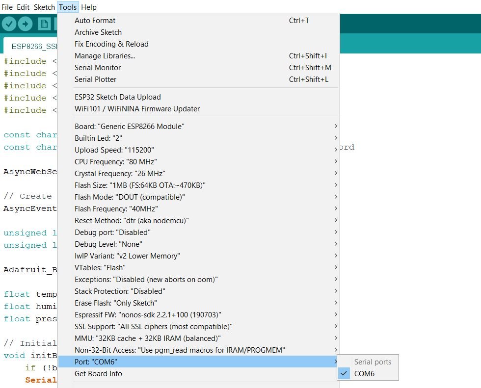
Make sure you choose the correct board and COM port before uploading your code to the board. Go to Tools > Board and select NodeMCU1.0.

Next, go to Tools > Port and select the appropriate port through which your board is connected.
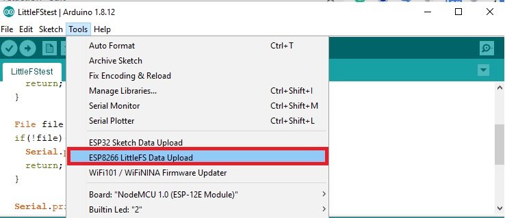
Now, we will upload the files into our ESP8266 board. Go to Tools > ESP8266 LittleFS Data Upload. After a few moments, the files will be uploaded.
Next, click on the upload button to upload the code into the ESP8266 development board.
After you have uploaded your code and the files to the ESP8266 development board, press its RST button.

In your Arduino IDE, open up the serial monitor and you will be able to see that the access point has been set. This is because the files are not yet created.

Now to connect the access point, open your mobile device’s WiFi option and search for available WiFi networks. You will see the name “ESP8266-WIFI-Manager”.
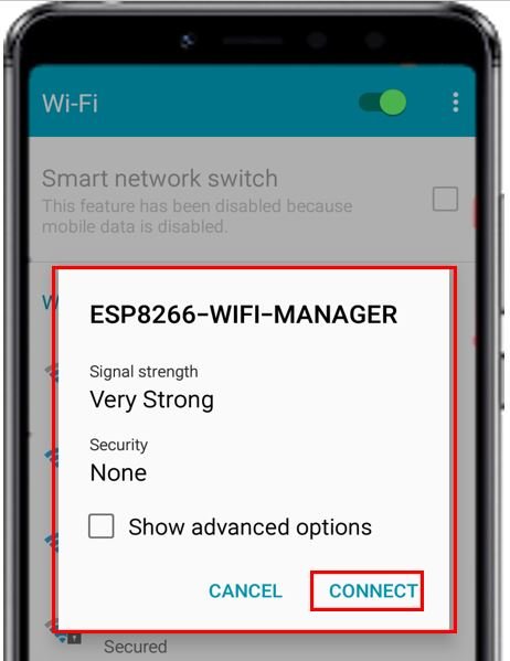
As we configured it as an open access point so you will be able to connect to it without any password.
Now go to the web browser of your mobile device and search with the IP address that was displayed in the serial monitor. The WiFi manager web page will open up.
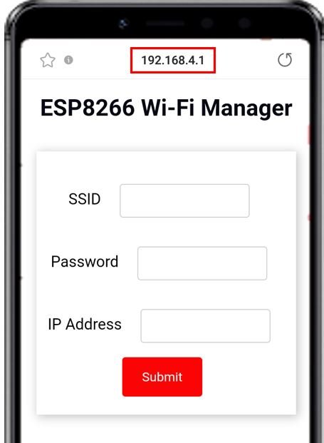
Now specify the SSID and password of your network along with an available IP address and press the Submit button. The following web page will open up indicating success.
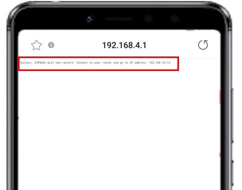
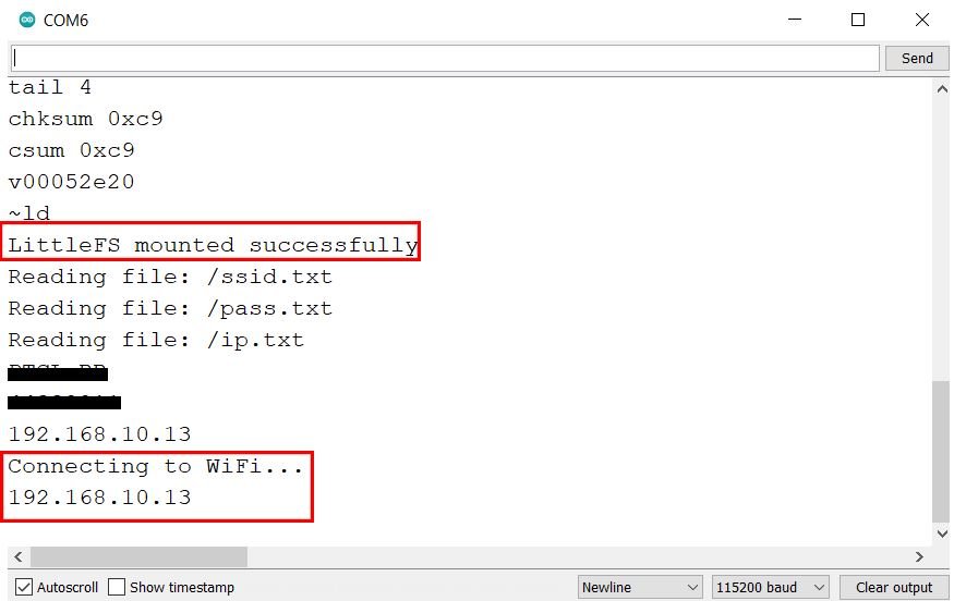
Now the ESP8266 board restarts and you can view it in the Serial Monitor. The files are read again and all three parameters get specified in the serial monitor. Additionally, the ESP8266 now connects to the IP address submitted by the user and goes in station mode.
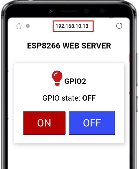
Now open a new web page and enter the IP address in the search bar and press enter. The ESP8266 web server opens which allows the user to control the onboard LED of their board.
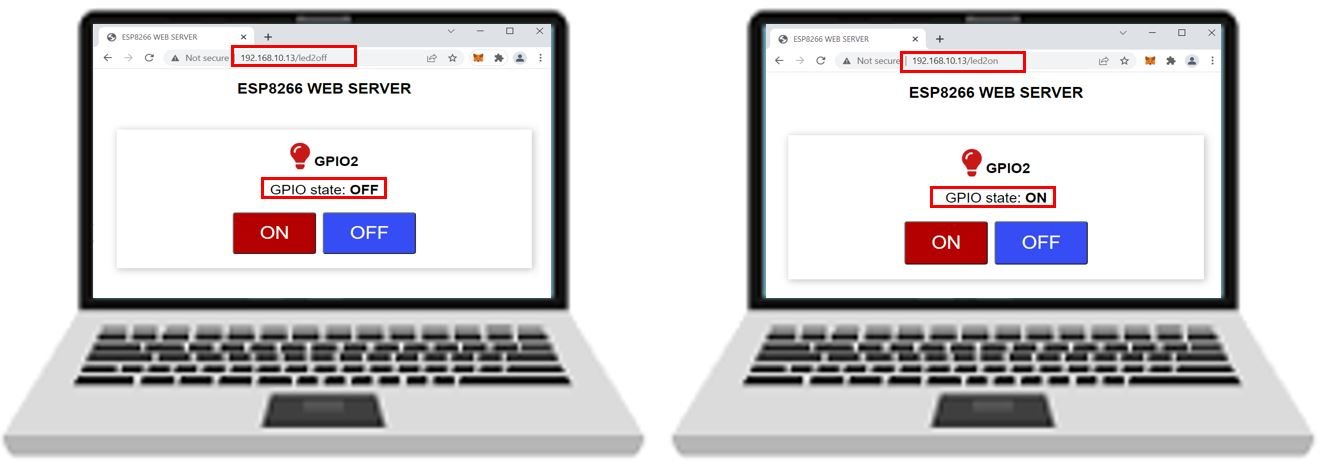
Now, press the ON and OFF buttons and the on-board LED will turn on and off accordingly. The GPIO state on the web server will also change and get updated.
By using the WiFi manager, we do not have to hardcode our network credentials in our Arduino script. WiFi-Manager sets the ESP8266 in soft access point mode and allows the user to specify the SSID, password, and an available IP address. Once your ESP8266 board is connected to the network, it will automatically work in station mode.
You may like to read:
- IoT Sound Pollution Monitoring System using ESP32 – Decibel Meter
- ESP32 Web Server Control DC Motor Speed using L298N Driver
- IoT Based Analog and Digital Clock using OLED and ESP32/ESP8266
- ESP32 MPU6050 Web Server
- ESP-MESH Getting Started using painlessMesh Library and ESP32/ESP8266
- ESP32 Multiple Sliders WebSocket Web Server